Transcription
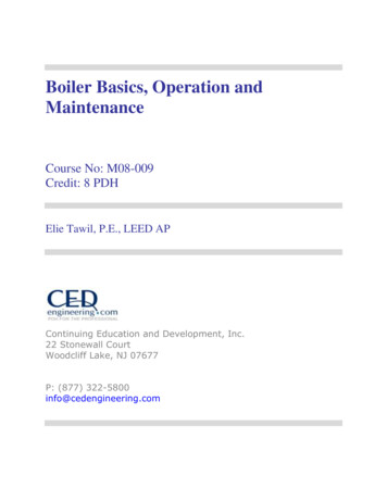
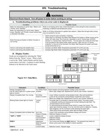
XIV. TroubleshootingWARNINGElectrical Shock Hazard. Turn off power to boiler before working on wiring.A. Troubleshooting problems where no error code is displayed.ConditionPossible CauseBoiler not responding to call for heat, “Status” and“Priority” show “Standby”.Boiler not responding to a call for heat, “Status”shows “Standby” and “Priority” shows Central Heator Domestic Hot Water.Boiler is not seeing call for heat. Check thermostat or zone wiring for loose connection,miswiring, or defective thermostat/zone control.Boiler is not firing, temperature is greater than setpoint. Water flow through boiler primaryloop non-existent or too low. Boiler Running but System or Boiler Circulator isnot runningHome is cold during mild weather daysHome is cold during cold weather days Check wiring for loose connection, miswiring.When there is a Domestic Hot Water Heat Request the System or Boiler pumps will beforced “off” when there “Run Pump for” parameter is set to “Central heat, off DHWdemand” or “Central Heat, Optional Priority”. This has been set to allow all of the heatto be provided for fast indirect water heater recovery. After one hour of “priorityprotection” or the end of the Domestic Hot Water Heat Request the system and boilerpumps will be free to run.Increase Low Boiler Water Temperature parameter 5 F (2.8 C) per day.Increase High Boiler Water Temperature parameter 5 F (2.8 C) per dayB. Display Faults:Faults are investigated by selecting the “Help”button from the “Home” screen. When a faultis active the “Help” button flashes and the homescreen turns a red color. Continue to select flashingbuttons to be directed to the Fault cause.Figure 14.1: Help MenuIndicationConditionDisplay Completely DarkNo 120Vac PowerFan off, LWCO lights off, no green power at Boilerlight on ControlDisplay Completely Dark, Fan runningNo 24VacPower to ControlBlinking Green power light on ControlControlFaultPossible CauseCheck breaker and wiring between breaker panel and boiler.- Blown high voltage fuse, Replacement Fuse Kit, part number 105349-01.-Display Completely Dark but Boiler fires**00FF or **ERFFER0011ER0012106375-01 - 4/16No 5 VdcPower to DisplayDisplay lostCommunicationwith ControlAdjustmentMode PasswordTimeoutControl Failed-Loose 120Vac connection wiring between boiler J-Box and transformerLoose 24 Vac connection wiring between transformer and Control.Blown low voltage fuse, Replacement Fuse Kit, part number 105349-01.The green light is connected to internal power supply. The power supplyis repeatedly starting and stopping (not normal) making the light flash. Themicroprocessors are not running.Try disconnecting all terminals except 24VAC to power the Control. Thegreen light should be steady. If it is not, then the control is defective. If steady,start plugging in all the connectors while watching the green light.When faulty wiring reconnected, green light will begin to flash.Loose 5 Vdc connection wiring between display and ControlDefective Display or Control.Loose or defective display harnessDefective DisplayDefective ControlThe Control and Display are NOT defective. The password has timed out.Simply cycle power to the Display to restore operation.- Defective Control. Replace Sage.135
XIV. Troubleshooting (continued)C. Help Screen FaultsIndicationConditionZone Panel 1SetupFlashingZone PanelFailureZone PanelSetupPossible CauseZone Panel 1 communication lost, typical for Panel 1 through 4: The zone panel’scommunication was established and then lost. Check the following to correct theissue: Wiring between panel and boiler. Zone panel DIP switch settings have changed:- Set Master/Slave switch to “Master”- Set Zone Control switch ZC1 to “ON”- Cycle powerZone Panel Electronics Failure: A Zone PanelFlashingDuplicate Zone: The Control has detected duplicate zone panel numbers. Check thefollowing to correct: Each Zone Control DIP Switch must be set to a Unique setting:FlashingDuplicateZoneFlashingNote that when multiple ZC switches are set on ON the Zone Panelis reported as Zone Panel 1.SequencerSetupSequencerSetupFaultBoiler SizeSetupBoilerSizeFaultThis alarm is active if the slave boiler has lost communication with the SequenceMaster. Check the following:- RJ 45 peer-to-peer network disconnected- Sequencer Master was Enabled and then Disabled- Master’s Boiler has been powered down.- To clear fault restore communication or cycle powerWARNING!Boiler size setting may not match actual boiler size.The Boiler size setting determines min, max and light-off blower speeds. Incorrectboiler size can cause hazardous burner conditions and improper operation that mayresult in PROPERTY LOSS, PHYSICAL INJURY, OR DEATH.Refer to page 112 for boiler size setting instructions.D. Help Screen Diagnostic FeaturesIndicationPossible CauseLockout History is stored in a first-in, first-out basis. Each History file is stored with boiler run hour of when thelockout occurred.The “When happened” and “Current” provide:- “Current” is the run hour and status the boiler just finished.- “When happened” is the run hour and status when the lockout occurred.For Service Contact:CONTRACTOR NAMECONTRACTOR ADDRESS 1CONTRACTOR ADDRESS 2PHONE NUMBER136The user is given the contact information of the responsible service provider. Refer to page 119 for data entryinstructions.106375-01 - 4/16
XIV. Troubleshooting (continued)E. Active Fault Screen FaultsIndicationConditionLimit String StatusLimit StringFaultSensor StatusNOTE: Since the limit string items are wired in series, all limits downstream of the“open” limit will also appear on the screen as “open” (blinking) icons regardless ofwhether or not they are actually open. The Air Proving Switch is wired independent toall other limits. The Air Proving Switch is only required to be closed during boiler prepurge. It is normal for it to be open during run mode.The Sensor Status screen shows the status of all sensors. Possible states include:None: Feature requiring this sensor has not been selected.Normal: Sensor is working normally.Shorted: Sensor is shorted or is defective.Open: There is a break in the wiring between the Control and the sensor or thesensor is defectiveSensor FaultOut of Range: Sensor is defective or is being subjected to electrical noise.Unreliable:Sensor is defective or is being subjected to electrical noise.When a sensor fails “opened” or “shorted” the value is changed to reverse video(background black and value white) “024” or “768” respectively to indicate that there isa fault with the sensor.The following messages appear when the firing rate is limited or reduced to help avoida lockout or save energy.Rate LimitRate LimitEMS StatusPossible CauseThe Limit String Status screen shows the safety limit status. A contact icon, either“open” or “closed”, graphically represents each safety limit. The “closed” contact iconis steady; the “open” contact icon is blinking. For example, the screen shown to the leftillustrates a “closed” external limit contact and an “open’ LWCO contact.Refer to Hard Lockout section for corrective actions- High Stack Temperature Limit- High Supply Temperature Limit- High Differential Temperature LimitThe following messages appear as part of normal start and stop sequences:- Minimum Modulation (normal start/stop sequence)- Low Fire Hold Rate: Low fire hold rate is a normal start-up rate hold used to helpensure system temperature feedback prior to release to modulation. Low FireHold Time may be adjusted. Refer to the “Changing Adjustable Parameters”,Paragraph F, for additional information.- Maximum Expected Heat Rate: Maximum Expected Heat Rate limit is a normalstart-up rate hold used to save energy. This limit helps reduce extra cyclesand save energy. Boiler is free to modulate up to the sum of the active zones anddomestic hot water expected heat rates. Each zone heat rate is adjustable andmay be modified under the modulation menu. Refer to the “Changing AdjustableParameters”, Paragraph F, for additional information.The Energy Management System (EMS) fault screen provides input fault status. Whenan input is shown as “Not Selected” it is not required for this application or has not yetbeen selected. These options are selected under the “Energy Management” Adjustmode menu.EnergyModbus Input FailureManagementSystem Fault4-20mA Input Failure106375-01 - 4/16If a modus input is selected and out of range or not presenta “535” value is shown reverse video (background black andvalue white). To fix the problem check the input source andcheck that the input is properly connected.Failure status for the 4-20mA input is the same as shownunder Sensor Fault.137
XIV. Troubleshooting (continued)F. Troubleshooting problems where a Soft Lockout Code is displayed. When a soft lockout occurs, theboiler will shut down, the display will turn red and the “Help” button will “blink”. Select the “blinking” “Help” button todetermine the cause of the soft lockout. The boiler will automatically restart once the condition that caused the lockout iscorrected.Soft Lockout Codes DisplayedLockoutNumberConditionBoiler Safety Limit wired to terminals J6-1 or3 OPEN:Boiler Safety Limit External Limit.Open Optional LWCO23Blocked Flue/Inlet Switch wired to terminalsBoiler Safety LimitJ5-1 OPENOpen7Return sensor(10 KOhms) fault8Supply sensor(10 KOhms) fault10Stack sensor(10 KOhms) fault11Ignition failurePossible CauseExternal Limit: Water temperature is higher than External Limit setting. See “HardLockout 4” for additional information. External device not used and jumper not installed. External Limit device is defective. Loose wiring to limit deviceOptional Low Water Cut Off (LWCO) If yellow light on LWCO is on, system is low on water. Ensure air ventis unobstructed and properly functioning as a blocked air vent can resultin low water indication. If neither yellow or green light on LWCO is on, check LWCO harness. Blocked Flue/Inlet Switch contact open - check for blocked flue/air intake.NOTEBlocked Flue/Inlet Switch Special NoteBefore a call for heat the air pressure switch is closed. When there is a callfor heat with a blocked vent the air pressure switch will open (due to excessivepressure of the blower against a blocked flue pipe) after the blower starts. Thecontrol stops the start sequence and stops the blower. After the blower stopsthe pressure switch re-closes and the cycle continues. The displays showsthe cause of trip for only the time the pressure switch is open.Shorted or open return temperature sensor. Shorted or mis-wired return sensor wiring.Defective return sensor.Shorted or open supply temperature sensor. Shorted or mis-wired supply sensor wiring.Defective supply sensor.Shorted or open flue gas (stack) temperature sensor. Flame failure after 5 tries to restart. Flamerod not detecting flame. Condensate trap plugged. 138Shorted or mis-wired flue temperature sensor wiring.Defective flue temperature sensor.No gas pressure.Gas pressure under minimum value shown on rating plate.Gas line not completely purged of air.Defective Electrode.Loose burner ground connection.Defective Ignition Cable.Defective gas valve (check for 24 Vac at harness during trial for ignitionbefore replacing valve).Air-fuel mixture out of adjustment - consult factory.Defective or fouled electrode.Plugged drain line in trap.106375-01 - 4/16
XIV. Troubleshooting (continued)Soft Lockout Codes Displayed (continued)LockoutNumberCondition13 Flame rodshorted to ground Flame rod shorted to groundCondensate Trap plugged.14DifferentialTemperature rise between supply and returnTemperature inlet/ is too high.outlet highThe Control is reading a return sensor15temperature higher than the supply sensorReturn temptemperature. Condition must be present forhigher than supply at least 75 seconds for this error code toappear.16Supply temp hasrisen too quicklySupply water temperature has risen tooquickly.Possible Cause Shorted or mis-wired flame rode wiring.Defective flame rod.Plugged drain line in trap. Inadequate boiler water flow. Verify that circulator is operating and thatcirculator and piping are sized per Water Piping and Trim Section of thismanual. Flow through boiler reversed. Verify correct piping and circulatororientation.No boiler water flow. Verify that system is purged of air and that appropriatevalves are open.Sensor wiring reversed.Supply or return sensor defective.See possible causes for “Hard Lockout 4”.Inadequate boiler water flow.Verify that circulator is operating and that circulator and piping are sizedper Water Piping and Trim Section of this manual. 17Normal waiting forNormal waiting for blower speed to matchblower speed topurge and light-off setpoint.match purge andlight-off setpoint.27Undefined FaultUndefined Fault28 or 53Air Proving Switch Air Proving Switch Failed to CloseFailed to Close54Air Proving SwitchAir Proving Switch Failed to OpenFailed to Open106375-01 - 4/16 Consult Factory.The air proving switch has failed to close; Check switch, check switch connection and wiring. Blocked vent, blocked inlet, blocked or disconnected air switch tube,blocked heat exchanger or burner. Something is blocking air/flue gas flow through boilerThe air proving switch has failed closed, check switch is operating properly.The air proving switch is “Closed” when it should be “Open”. The air provingswitch is checked for proper function before the blower is started and the startsequence is allowed to continue. If the air switch is closed before the bloweris started (when there is no air flow) first a soft lockout is initiated and then amanual reset hard lockout results. The possible cause of the air proving switchto be closed or fail to open is as follows: The air proving switch is jumpered. The air proving switch is defective. The blower is running before the start sequence starts the blower. Thiscan be caused by a loss of communication between the blower andControl. The blower goes to high speed when there is no communicationbetween the Control and the blower. Possible cause of loss ofcommunication is a defective wiring harness, blower or Control.139
XIV. Troubleshooting (continued)G. Troubleshooting problems where a Hard Lockout Code is displayed. When a hard lockout occurs, theboiler will shut down, the display will turn red and the “Help” button will “blink”. Select the “blinking” “Help” button todetermine the cause of the Hard Lockout. Once the condition that caused the lockout is corrected, the boiler will need to bemanually reset using the Reset button on the “Active Fault” display or located on the Control.Alarm Output ContactThe Control includes an alarm output contact located on the low voltage terminal board. The alarm contact closes when theControl goes into a manual reset Hard Lockout. The list of Hard Lockouts is shown below.Hard Lockout Codes DisplayedLockout NumberConditionPossible Cause 4Supply High LimitControl supply sensor detectedtemperatures in excess of 210 F. Heating load at time of error was far below the minimum firingrate of the boiler.Defective system circulator or no flow in primary loop.Defective boiler circulator, no flow or insufficient flow in boiler loop.Control system miswired so that the boiler operation ispermitted when no zones are calling.Heat exchanger needs to be cleaned.Boiler over-fired.Air-fuel mixture out of adjustment - consult factory.Defective gas valve - make sure inlet pressure is belowmaximum on rating plate before replacing valve.Plugged drain line in trap.Loose connection in 120 VAC blower wiring.Loose or miswired blower speed harness.Defective blowerLoose connection in 120 VAC blower wiring.Loose or miswired blower speed harness.Defective blower A flame signal was present when there 12should be no flame.Flame detected out of sequence Condensate trap plugged. Blower is not running at Light-off rate18when it should or blower speed signal Light off rate proving failednot being detected by Control. Blower is not running at Purge rate19when it should or blower speed signal Purge rate proving failednot being detected by Control. 20Unacceptable Control Safety relatedSafety Parameter verification required. Contact factory.Invalid Safety Parametersparameter detected.21Unacceptable Control ModulationReset the control.Invalid Modulation Parameter related parameter detected.Safety related parameter change hasSafety related Control parameter has been changed and verification22been detected and a verification hashas not been performed.Safety data verification needednot been completed. Loose connection in 24Vac VAC power wiring. Loose or miswired 24Vac harness.23Control 24Vac control power is high Miswired wiring harness causing power supply short to ground.24VAC Voltage low/highor low. Defective transformer. Transformer frequency, voltage and VA do not meetspecifications.24Power detected at fuel valve output Reset the control. If problem reoccurs, replace the Control.Fuel Valve Errorwhen fuel valve should be off.25Internal control failure. Reset the control. If problem reoccurs, replace the Control.Hardware Fault26Internal control failure. Reset the control. If problem reoccurs, replace the Control.Internal Fault27Undefined Fault Reset the Control. If problem reoccurs, replace the Control.Undefined Fault54Air Proving SwitchAir Proving Switch Failed to OpenSee Soft Lockout 54.Failed to Open6Stack High Limit140Control Flue gas (Stack) sensordetected temperatures in excess of214 F (101 C).106375-01 - 4/16
No gas pressure. Gas pressure under minimum value shown on rating plate. Gas line not completely purged of air. Defective Electrode. Loose burner ground connection. Defective Ignition Cable. Defective gas valve (check for 24 Vac at harness during trial for ignition before replacing valve).