Transcription
ND-70917 (E)ISSUE 1STOCK # 151973 Remote PIM System ManualFEBRUARY, 2000NEC America, Inc.
LIABILITY DISCLAIMERNEC America, Inc. reserves the right to change the specifications,functions, or features, at any time, without notice.NEC America, Inc. has prepared this document for use by itsemployees and customers. The information contained herein isthe property of NEC America, Inc. and shall not be reproducedwithout prior written approval from NEC America, Inc.NEAX is a registered trademark of NEC Corporation.Copyright 2000NEC America, Inc.Printed in U.S.A.
ISSUE No.ISSUE No.PAGE No.PAGE 3016813116913217013317111721i34ISSUE 1DATEFEBRUARY, 2000ISSUE 2DATEISSUE 5DATE34ISSUE 3DATEISSUE 6DATE2678ISSUE 4DATEISSUE 7DATE5ISSUE 8DATEIVS2NEAX2000Remote PIM System ManualRevision Sheet 1/2ND-70917 (E)
ISSUE No.ISSUE No.PAGE No.PAGE 81891901911921931941951961971981234ISSUE 1DATEFEBRUARY, 20006781ISSUE 2DATEISSUE 5DATE534ISSUE 3DATEISSUE 6DATE2678ISSUE 4DATEISSUE 7DATE5ISSUE 8DATEIVS2NEAX2000Remote PIM System ManualRevision Sheet 2/2ND-70917 (E)
NEAX2000 IVS2Remote PIM System ManualTABLE OF CONTENTSPageLIST OF FIGURES . . . . . . . . . . . . . . . . . . . . . . . . . . . . . . . . . . . . . . . . . . . . . . . . . . . . . . . .iiiLIST OF TABLES . . . . . . . . . . . . . . . . . . . . . . . . . . . . . . . . . . . . . . . . . . . . . . . . . . . . . . . . .ivINTRODUCTION . . . . . . . . . . . . . . . . . . . . . . . . . . . . . . . . . . . . . . . . . . . . . . . . . . . . . . . . .1PURPOSE . . . . . . . . . . . . . . . . . . . . . . . . . . . . . . . . . . . . . . . . . . . . . . . . . . . . . . . . . . . . . . . . . .USING THIS MANUAL . . . . . . . . . . . . . . . . . . . . . . . . . . . . . . . . . . . . . . . . . . . . . . . . . . . . . . . . .REFERENCE MANUALS . . . . . . . . . . . . . . . . . . . . . . . . . . . . . . . . . . . . . . . . . . . . . . . . . . . . . . .CHAPTER 1112GENERAL INFORMATION . . . . . . . . . . . . . . . . . . . . . . . . . . . . . . . . . . . . .3SYSTEM OUTLINE . . . . . . . . . . . . . . . . . . . . . . . . . . . . . . . . . . . . . . . . . . . . . . . . . . . . . . . . . . .PIM CONFIGURATION . . . . . . . . . . . . . . . . . . . . . . . . . . . . . . . . . . . . . . . . . . . . . . . . . . . . . . . .SYSTEM CONFIGURATION . . . . . . . . . . . . . . . . . . . . . . . . . . . . . . . . . . . . . . . . . . . . . . . . . . . .System Configuration for T1 . . . . . . . . . . . . . . . . . . . . . . . . . . . . . . . . . . . . . . . . . . . . . . . . .System Configuration for E1 . . . . . . . . . . . . . . . . . . . . . . . . . . . . . . . . . . . . . . . . . . . . . . . . .REQUIRED EQUIPMENT . . . . . . . . . . . . . . . . . . . . . . . . . . . . . . . . . . . . . . . . . . . . . . . . . . . . . .SYSTEM CAPACITY . . . . . . . . . . . . . . . . . . . . . . . . . . . . . . . . . . . . . . . . . . . . . . . . . . . . . . . . . .System Capacity for T1 . . . . . . . . . . . . . . . . . . . . . . . . . . . . . . . . . . . . . . . . . . . . . . . . . . . . .System Capacity for E1 . . . . . . . . . . . . . . . . . . . . . . . . . . . . . . . . . . . . . . . . . . . . . . . . . . . . .SYSTEM CONDITIONS . . . . . . . . . . . . . . . . . . . . . . . . . . . . . . . . . . . . . . . . . . . . . . . . . . . . . . . .TIME SLOT ALLOCATION . . . . . . . . . . . . . . . . . . . . . . . . . . . . . . . . . . . . . . . . . . . . . . . . . . . . . .Time Slot Allocation for T1 . . . . . . . . . . . . . . . . . . . . . . . . . . . . . . . . . . . . . . . . . . . . . . . . . . .Time Slot Allocation for E1 . . . . . . . . . . . . . . . . . . . . . . . . . . . . . . . . . . . . . . . . . . . . . . . . . .45667810101112131315CHAPTER 2INSTALLATION . . . . . . . . . . . . . . . . . . . . . . . . . . . . . . . . . . . . . . . . . . . . . .17PRECAUTIONS . . . . . . . . . . . . . . . . . . . . . . . . . . . . . . . . . . . . . . . . . . . . . . . . . . . . . . . . . . . . . .Static Electricity Guard . . . . . . . . . . . . . . . . . . . . . . . . . . . . . . . . . . . . . . . . . . . . . . . . . . . . .INSTALLATION PROCEDURE . . . . . . . . . . . . . . . . . . . . . . . . . . . . . . . . . . . . . . . . . . . . . . . . . .Installation Procedure for Main Site . . . . . . . . . . . . . . . . . . . . . . . . . . . . . . . . . . . . . . . . . . . .Installation Procedure for Remote Site . . . . . . . . . . . . . . . . . . . . . . . . . . . . . . . . . . . . . . . . .INSTALLATION FOR MAIN SITE. . . . . . . . . . . . . . . . . . . . . . . . . . . . . . . . . . . . . . . . . . . . . . . . .Mounting DAIA Card for T1 / DAID Card for E1 . . . . . . . . . . . . . . . . . . . . . . . . . . . . . . . . . .Mounting DAIC Card for T1 / DAIF Card for E1 . . . . . . . . . . . . . . . . . . . . . . . . . . . . . . . . . . .Mounting FP Card . . . . . . . . . . . . . . . . . . . . . . . . . . . . . . . . . . . . . . . . . . . . . . . . . . . . . . . . .Mounting M10 Card . . . . . . . . . . . . . . . . . . . . . . . . . . . . . . . . . . . . . . . . . . . . . . . . . . . . . . . .BUS Cable Connection . . . . . . . . . . . . . . . . . . . . . . . . . . . . . . . . . . . . . . . . . . . . . . . . . . . . .INSTALLATION FOR REMOTE SITE . . . . . . . . . . . . . . . . . . . . . . . . . . . . . . . . . . . . . . . . . . . . .Mounting DAIB Card for T1 / DAIE Card for E1 . . . . . . . . . . . . . . . . . . . . . . . . . . . . . . . . . . .Mounting DAIC Card for T1 / DAIF Card for E1 . . . . . . . . . . . . . . . . . . . . . . . . . . . . . . . . . . .Mounting M10 Card . . . . . . . . . . . . . . . . . . . . . . . . . . . . . . . . . . . . . . . . . . . . . . . . . . . . . . . .BUS Cable Connection . . . . . . . . . . . . . . . . . . . . . . . . . . . . . . . . . . . . . . . . . . . . . . . . . . . . .Mounting Line/Trunk Card for T1 . . . . . . . . . . . . . . . . . . . . . . . . . . . . . . . . . . . . . . . . . . . . . .1818212122232323232324292929293031NEAX2000 IVS2 Remote PIM System ManualND-70917 (E), Issue 1.0Page i
TABLE OF CONTENTSPageMounting Line/Trunk Card for E1 . . . . . . . . . . . . . . . . . . . . . . . . . . . . . . . . . . . . . . . . . . . . . .Power Failure Transfer (AUC) . . . . . . . . . . . . . . . . . . . . . . . . . . . . . . . . . . . . . . . . . . . . . . . .Power Failure Transfer (8PFT) . . . . . . . . . . . . . . . . . . . . . . . . . . . . . . . . . . . . . . . . . . . . . . .CONNECTION BETWEEN MAIN SITE AND REMOTE SITE . . . . . . . . . . . . . . . . . . . . . . . . . . .DAI Connection at Main Site . . . . . . . . . . . . . . . . . . . . . . . . . . . . . . . . . . . . . . . . . . . . . . . . .DAI Connection at Remote Site . . . . . . . . . . . . . . . . . . . . . . . . . . . . . . . . . . . . . . . . . . . . . . .Optical Cable Connection . . . . . . . . . . . . . . . . . . . . . . . . . . . . . . . . . . . . . . . . . . . . . . . . . . .MP RESET . . . . . . . . . . . . . . . . . . . . . . . . . . . . . . . . . . . . . . . . . . . . . . . . . . . . . . . . . . . . . . . . . .3539424747505155CHAPTER 3TROUBLESHOOTING . . . . . . . . . . . . . . . . . . . . . . . . . . . . . . . . . . . . . . . . .57CHAPTER 4CIRCUIT CARD INFORMATION . . . . . . . . . . . . . . . . . . . . . . . . . . . . . . . . .65HOW TO READ THIS CHAPTER. . . . . . . . . . . . . . . . . . . . . . . . . . . . . . . . . . . . . . . . . . . . . . . . .MOUNTING LOCATION OF CIRCUIT CARD . . . . . . . . . . . . . . . . . . . . . . . . . . . . . . . . . . . . . . .LIST OF REQUIRED CARDS. . . . . . . . . . . . . . . . . . . . . . . . . . . . . . . . . . . . . . . . . . . . . . . . . . . .PN-CP15 (FP) . . . . . . . . . . . . . . . . . . . . . . . . . . . . . . . . . . . . . . . . . . . . . . . . . . . . . . . . . . . .PN-DAIA (DAI) . . . . . . . . . . . . . . . . . . . . . . . . . . . . . . . . . . . . . . . . . . . . . . . . . . . . . . . . . . . .PN-DAIB (DAI) . . . . . . . . . . . . . . . . . . . . . . . . . . . . . . . . . . . . . . . . . . . . . . . . . . . . . . . . . . . .PN-DAIC (DAI) . . . . . . . . . . . . . . . . . . . . . . . . . . . . . . . . . . . . . . . . . . . . . . . . . . . . . . . . . . . .PN-DAID (DAI) . . . . . . . . . . . . . . . . . . . . . . . . . . . . . . . . . . . . . . . . . . . . . . . . . . . . . . . . . . . .PN-DAIE (DAI) . . . . . . . . . . . . . . . . . . . . . . . . . . . . . . . . . . . . . . . . . . . . . . . . . . . . . . . . . . . .PN-DAIF (DAI) . . . . . . . . . . . . . . . . . . . . . . . . . . . . . . . . . . . . . . . . . . . . . . . . . . . . . . . . . . . .PN-M10 (M10) . . . . . . . . . . . . . . . . . . . . . . . . . . . . . . . . . . . . . . . . . . . . . . . . . . . . . . . . . . . .6667686971768083899397Page iiNEAX2000 IVS2 Remote PIM System ManualND-70917 (E), Issue 1.0
LIST OF FIGURESFigureTitleFigure 1-1Figure 1-2Figure 1-3Figure 1-4Figure 1-4Figure 1-5Figure 2-1Figure 2-1Figure 2-2Figure 2-3Figure 2-4Figure 2-4Figure 2-5Figure 2-6Figure 2-6Figure 2-7Figure 2-8Figure 2-9Figure 2-10Figure 2-10Figure 2-11Figure 2-12Figure 2-13Figure 2-13Figure 2-14Figure 2-15Figure 2-15Figure 2-16Figure 2-17Figure 2-18Figure 2-19Figure 2-20Figure 2-21Figure 2-22Figure 2-23Figure 2-24Figure 2-25Figure 2-26Figure 2-26Figure 2-27Figure 2-27Figure 4-1Outline of Remote PIM System . . . . . . . . . . . . . . . . . . . . . . . . . . . . . . . . . . . . . . . . . .System Configuration for T1 . . . . . . . . . . . . . . . . . . . . . . . . . . . . . . . . . . . . . . . . . . . .System Configuration for E1 . . . . . . . . . . . . . . . . . . . . . . . . . . . . . . . . . . . . . . . . . . . .Time Slot Allocation for T1 (1 of 2) . . . . . . . . . . . . . . . . . . . . . . . . . . . . . . . . . . . . . . .Time Slot Allocation for T1 (2 of 2) . . . . . . . . . . . . . . . . . . . . . . . . . . . . . . . . . . . . . . .Time Slot Allocation for E1 . . . . . . . . . . . . . . . . . . . . . . . . . . . . . . . . . . . . . . . . . . . . .Static Electricity Guard (1 of 2) . . . . . . . . . . . . . . . . . . . . . . . . . . . . . . . . . . . . . . . . . .Static Electricity Guard (2 of 2) . . . . . . . . . . . . . . . . . . . . . . . . . . . . . . . . . . . . . . . . . .Installation Procedure for Main Site . . . . . . . . . . . . . . . . . . . . . . . . . . . . . . . . . . . . . . .Installation Procedure for Remote Site . . . . . . . . . . . . . . . . . . . . . . . . . . . . . . . . . . . .BUS Cable Connection (1 of 2) . . . . . . . . . . . . . . . . . . . . . . . . . . . . . . . . . . . . . . . . . .BUS Cable Connection (2 of 2) . . . . . . . . . . . . . . . . . . . . . . . . . . . . . . . . . . . . . . . . . .DAIA/DAID Between DAIA/DAID Cable Connection . . . . . . . . . . . . . . . . . . . . . . . . . .DAIA/DAID Between DAIC/DAIF Cable Connection (1 of 2) . . . . . . . . . . . . . . . . . . . .DAIA/DAID Between DAIC/DAIF Cable Connection (2 of 2) . . . . . . . . . . . . . . . . . . . .DAIB/DAIE Between DAIC/DAIF Cable Connection . . . . . . . . . . . . . . . . . . . . . . . . . .Mounting Location of Line/Trunk Card for T1 . . . . . . . . . . . . . . . . . . . . . . . . . . . . . . .Location of Each LEN for T1 . . . . . . . . . . . . . . . . . . . . . . . . . . . . . . . . . . . . . . . . . . . .LTC Connector Pin Arrangement for T1 (1 of 2) . . . . . . . . . . . . . . . . . . . . . . . . . . . . .LTC Connector Pin Arrangement for T1 (2 of 2) . . . . . . . . . . . . . . . . . . . . . . . . . . . . .Mounting Location of Line/Trunk Card for E1 . . . . . . . . . . . . . . . . . . . . . . . . . . . . . . .Location of Each LEN for E1 . . . . . . . . . . . . . . . . . . . . . . . . . . . . . . . . . . . . . . . . . . . .LTC Connector Pin Arrangement for E1 (1 of 2) . . . . . . . . . . . . . . . . . . . . . . . . . . . . .LTC Connector Pin Arrangement for E1 (2 of 2) . . . . . . . . . . . . . . . . . . . . . . . . . . . . .PFT Connection Outline (AUC) . . . . . . . . . . . . . . . . . . . . . . . . . . . . . . . . . . . . . . . . . .MDF Cross Connection for PFT (AUC) (1 of 2) . . . . . . . . . . . . . . . . . . . . . . . . . . . . . .MDF Cross Connection for PFT (PN-AUC) (2 of 2) . . . . . . . . . . . . . . . . . . . . . . . . . . .PFT Connection Outline (8PFT) . . . . . . . . . . . . . . . . . . . . . . . . . . . . . . . . . . . . . . . . .Connection of 25-Pair Cable and PZ-8PFTB . . . . . . . . . . . . . . . . . . . . . . . . . . . . . . . .PFT Connector Pin Assignment . . . . . . . . . . . . . . . . . . . . . . . . . . . . . . . . . . . . . . . . .MDF Cross Connection for PFT (8PFT) (1 of 2) . . . . . . . . . . . . . . . . . . . . . . . . . . . . .MDF Cross Connection for PFT (8PFT) (2 of 2) . . . . . . . . . . . . . . . . . . . . . . . . . . . . .DAI Cable Connection via LTC Connector (Main Site) . . . . . . . . . . . . . . . . . . . . . . . .Example of DAI MDF Cross Connection via LTC Connector (Main Site) . . . . . . . . . .DAI Cable Connection via CN Connector (Main Site) . . . . . . . . . . . . . . . . . . . . . . . . .DAI Cable Connection via CN Connector (Remote Site) . . . . . . . . . . . . . . . . . . . . . . .Outline of Optical Cable Connection . . . . . . . . . . . . . . . . . . . . . . . . . . . . . . . . . . . . . .Example of M10 MDF Cross Connection via LTC Connector (Main Site) (1 of 2) . . . .Example of M10 MDF Cross Connection via LTC Connector (Main Site) (2 of 2) . . . .Example of M10 MDF Cross Connection via CN Connector (Remote Site) (1 of 2) . .Example of M10 MDF Cross Connection via CN Connector (Remote Site) (2 of 2) . .Mounting Location of Circuit Card . . . . . . . . . . . . . . . . . . . . . . . . . . . . . . . . . . . . . . . .NEAX2000 IVS2 Remote PIM System ManualND-70917 (E), Issue 38394041424344454647484950515253545567Page iii
LIST OF TABLESTableTitleTable 1-1Table 1-2Table 1-3Table 1-4Table 2-1Table 2-2Table 3-1Table 4-1PIM Configuration . . . . . . . . . . . . . . . . . . . . . . . . . . . . . . . . . . . . . . . . . . . . . . . . . . . .Required Equipment . . . . . . . . . . . . . . . . . . . . . . . . . . . . . . . . . . . . . . . . . . . . . . . . . .System Capacity for T1 . . . . . . . . . . . . . . . . . . . . . . . . . . . . . . . . . . . . . . . . . . . . . . . .System Capacity for E1 . . . . . . . . . . . . . . . . . . . . . . . . . . . . . . . . . . . . . . . . . . . . . . . .LTC Connector Accommodation for T1 . . . . . . . . . . . . . . . . . . . . . . . . . . . . . . . . . . . .LTC Connector Accommodation for E1 . . . . . . . . . . . . . . . . . . . . . . . . . . . . . . . . . . . .Remedial Action on Each Lamp Status . . . . . . . . . . . . . . . . . . . . . . . . . . . . . . . . . . . .List of Required Cards . . . . . . . . . . . . . . . . . . . . . . . . . . . . . . . . . . . . . . . . . . . . . . . . .Page ivPage58101131355868NEAX2000 IVS2 Remote PIM System ManualND-70917 (E), Issue 1.0
INTRODUCTIONPurposeINTRODUCTIONPURPOSEThis manual explains the system outline and installation procedure for providing the Remote PIMto the NEAX2000 IVS2.USING THIS MANUALThis manual contains the following chapters:CHAPTER 1GENERAL INFORMATIONThis chapter explains the outline of system configuration, required equipment, system capacity,system conditions, and time slot allocation.CHAPTER 2INSTALLATIONThis chapter explains how to install the Remote PIM hardware. This chapter describes only theinstallation procedure required for providing the Remote PIM System. Refer to the InstallationProcedure Manual for general installation procedures.CHAPTER 3TROUBLESHOOTINGThis chapter explains the method for fault diagnosis and troubleshooting when maintenance personnel detect fault occurrences by lamp indication on DAIA/DAIB/DAIC/DAID/DAIE/DAIF andM10 cards. For other system faults, refer to the Maintenance Manual.CHAPTER 4CIRCUIT CARD INFORMATIONThis chapter explains the mounting location, the meaning of lamp indications, and the method ofswitch settings of each circuit card for the Remote PIM.NEAX2000 IVS2 Remote PIM System ManualND-70917 (E), Issue 1.0Page 1
INTRODUCTIONReference ManualsREFERENCE MANUALSRefer to the following manuals during installation:Installation Procedure ManualProvides the installation procedures for the PBX system.Command ManualDescribes the Customer Administration Terminal (CAT)operation, command function, and setting data required forprogramming the PBX system.Office Data Programming Manual Contains the Customer Specification Sheets and OfficeData Programming Sheets.Maintenance ManualPage 2Describes the maintenance service features and therecommended troubleshooting procedures.NEAX2000 IVS2 Remote PIM System ManualND-70917 (E), Issue 1.0
CHAPTER 1GENERAL INFORMATIONThis chapter explains the outline of system configuration, requiredequipment, system capacity, system conditions, and time slot allocation.NEAX2000 IVS2 Remote PIM System ManualND-70917 (E), Issue 1.0Page 3
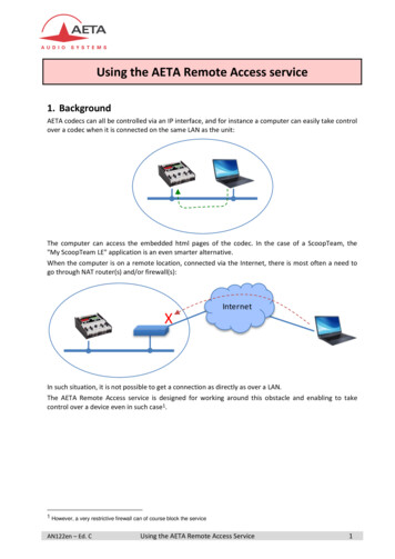
CHAPTER 1 GENERAL INFORMATIONSystem OutlineSYSTEM OUTLINERemote PIMs can be installed separately at the distance in one building, or between the officesvia the Public Switching Telephone Network (PSTN).The customers in the Remote Site can use the same service features as in the Main Site.Remote PIMs are connected to the Main Site by T1 (1.5 Mbps) / E1 (2 Mbps) digital interface.Figure 1-1 Outline of Remote PIM SystemPIM1 .5TM(21) /PIMOFFICE A(MAIN SITE)E 1)M(OFFICE B(REMOTE SITE)PIM1.5 M (T1) / 2 M (E1)1.5M( T1)/2M(OFFICE C(REMOTE SITE)E1)PIMOFFICE D(REMOTE SITE)Page 4NEAX2000 IVS2 Remote PIM System ManualND-70917 (E), Issue 1.0
CHAPTER 1 GENERAL INFORMATIONPIM ConfigurationPIM CONFIGURATIONOne PIM can be installed respectively as a Remote Site. A maximum of three Remote Sites canbe provided. The number of Remote Sites determines the number of PIMs in one system.Table 1-1 shows the available PIM configuration for the Remote PIM System.Table 1-1 PIM ConfigurationNUMBER OF PIM AT MAIN SITEAVAILABLE NUMBER OF REMOTE SITE1 PIM(1 FP)1232 PIM(1 FP)1233 PIM(2 FP)12–4 PIM(2 FP)12–5 PIM(3 FP)1––6 PIM(3 FP)1––7 PIM(4 FP)–––8 PIM(4 FP)–––NEAX2000 IVS2 Remote PIM System ManualND-70917 (E), Issue 1.0Page 5
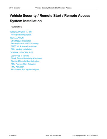
CHAPTER 1 GENERAL INFORMATIONSystem ConfigurationSYSTEM CONFIGURATIONSystem Configuration for T1Figure 1-2 shows the system configuration for T1.Figure 1-2 System Configuration for T1Main SiteRemote SiteRemote PIM1DAIA 1(FP1)DAIC 123 B Channel1 D Channel24 B Channel24 B ChannelDAIC 2DAIB(FP1)Line/TRKDAIC 1DAIC 2Remote PIM2DAIA 2(FP1)TDSW23 B Channel1 D ChannelDAIB(FP2)Line/TRK24 B ChannelDAIC 3DAIC 324 B ChannelDAIC 4DAIC 4Remote PIM3DAIA 3(FP1)23 B Channel1 D ChannelDAIB(FP3)Line/TRK24 B ChannelDAIC 5DAIC 524 B ChannelDAIC 6MPPage 6DAIC 6FP0NEAX2000 IVS2 Remote PIM System ManualND-70917 (E), Issue 1.0
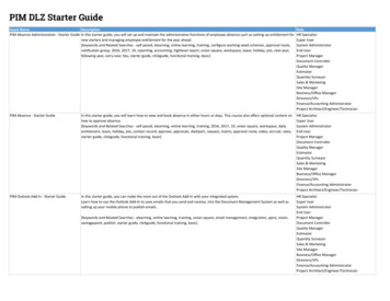
CHAPTER 1 GENERAL INFORMATIONSystem ConfigurationSystem Configuration for E1Figure 1-3 shows the system configuration for E1.Figure 1-3 System Configuration for E1Main SiteRemote SiteRemote PIM1DAID 1(FP1)DAIF 130 B Channel1 D Channel30 B ChannelDAIE(FP1)Line/TRKDAIF 1Remote PIM2DAID 2(FP2)TDSW30 B Channel1 D ChannelDAIE(FP2)Line/TRK30 B ChannelDAIF 2DAIF 2Remote PIM3DAID 3(FP3)30 B Channel1 D ChannelDAIE(FP3)Line/TRK30 B ChannelDAIF 3MPDAIF 3FP0NEAX2000 IVS2 Remote PIM System ManualND-70917 (E), Issue 1.0Page 7
CHAPTER 1 GENERAL INFORMATIONRequired EquipmentREQUIRED EQUIPMENTTable 1-2 shows the required equipment for providing the Remote PIM System.Table 1-2 Required Equipmen tEQUIPMENT FUNCTIONALNAMENAMEFUNCTIONPN-DAIADAIT1 Digital Trunk Interface (23B D, 1.5 Mbps) Card forRemote PIMAccommodates 24-channel PCM digital lines, and providesFirmware Processor and BUS interfaceOne through three cards must be provided at the Main Site,which corresponds to the number of the Remote Site.PN-DAIBDAIT1 Digital Trunk Interface (23B D, 1.5 Mbps) Card forRemote PIMAccommodates 24-channel PCM digital lines, and providesFirmware ProcessorOne card is required per Remote PIM at the Remote Site.PN-DAICDAIT1 Digital Trunk Interface (23B D, 1.5 Mbps) ChannelExpansion CardAccommodates 24-channel PCM digital linesOne through six cards can be provided at the Main Site.Two cards can be provided at the Remote Site.PN-DAIDDAIE1 Digital Trunk Interface (2 Mbps) Card for Remote PIMAccommodates 30-channel PCM digital lines and providesFirmware Processor and BUS interfaceOne though three cards must be provided at the Main Site,which corresponds to the number of the Remote Site.PN-DAIEDAIE1 Digital Trunk Interface (2 Mbps) Card for Remote PIMAccommodates 30-channel PCM digital lines and providesFirmware ProcessorOne card is required per Remote PIM at the Remote Site.PN-DAIFDAIE1 Digital Trunk Interface (2 Mbps) Channel Expansion CardAccommodates 30-channel PCM digital linesOne through three cards can be provided at the Main Site.One card can be provided at the Remote Site.Page 8NEAX2000 IVS2 Remote PIM System ManualND-70917 (E), Issue 1.0
CHAPTER 1 GENERAL INFORMATIONRequired EquipmentTable 1-2 Required Equipment (Continued)EQUIPMENT FUNCTIONALNAMENAMEFUNCTIONPN-CP15FPFirmware Processor CardProvides Line/Trunk interface, Memory (RAM 768 KB), andinter-module BUS interface. BUS interface functions as adriver/receiver of various signals, adjusts gate delay timingand cable delay timing, monitors I/O BUS and PCM BUS.When the system consists of three or more PIMs, one each ofthis card is mounted respectively in PIM0, PIM2, PIM4, andPIM6.For Remote PIM System, the FP card must be mounted onPIM0 at the Main Site, even if the system is 1-PIM/2-PIMconfiguration.PN-M10M10Optical Interface CardProvides internal optical modem to T1/E1 network or RemotePIMLine length : 10 km (6.25 miles) or lessLine coding: CMIRMT BUSCA-A–0.6 m (2 ft.) PCM Signal CableUsed for connecting between the DAIA/DAID card and theBUS connector on the PIM BWB17-TW-0.3CONN CA-A–0.3 m (1 ft.) Connection Cable Between the DAIA/DAID cardsRequired when multiple DAIA/DAID cards are mounted in aPIM at the Main Site48-TW-0.2CONN CA–NEAX2000 IVS2 Remote PIM System ManualND-70917 (E), Issue 1.00.2 m (0.7 ft.) Connection CableUsed for the following connection between the cards: DAIA-DAIC DAIB-DAIC DAIC-DAIC DAID-DAIF DAIE-DAIFPage 9
CHAPTER 1 GENERAL INFORMATIONSystem CapacitySYSTEM CAPACITYSystem Capacity for T1Table 1-3 shows the system capacity for T1.Table 1-3 System Capacity for T1DESCRIPTIONCAPACITYREMARKSMAIN PIMREMOTE PIMDAIA card3–DAIB card–1DAIC card62Line/Trunk Portson Remote Site–24NOTE 1Main PIM : 1 DAIARemote PIM: 1 DAIB48NOTE 1Main PIM : 1 DAIA, 1 DAICRemote PIM: 1 DAIB, 1 DAIC64NOTE 1Main PIM : 1 DAIA, 2 DAICRemote PIM: 1 DAIB, 2 DAIC1/233/425/617/80NOTE 2Number of PIM depends onthe number of Main PIM andRemote PIM.See "PIM Configuration" onPage 5.Number of PIMNOTE 1: One port is used for the control signaling channel.NOTE 2: When the Main Site consists of 7 or 8 PIMs, Remote PIM cannot be provided.Page 10NEAX2000 IVS2 Remote PIM System ManualND-70917 (E), Issue 1.0
CHAPTER 1 GENERAL INFORMATIONSystem CapacitySystem Capacity for E1Table 1-4 shows the system capacity for E1.Table 1-4 System Capacity for E1DESCRIPTIONCAPACITYREMARKSMAIN PIMREMOTE PIMDAID card3–DAIE card–1DAIF card31Line/Trunk Portson Remote Site–30Main PIM : 1 DAIDRemote PIM: 1 DAIE60Main PIM : 1 DAID, 1 DAIFRemote PIM: 1 DAIE, 1 DAIF1/233/425/617/80NOTENumber of PIM depends onthe number of Main PIM andRemote PIM.See "PIM Configuration" onPage 5.Number of PIMNOTE:When the Main Site consists of 7 or 8 PIMs, Remote PIM cannot be provided.NEAX2000 IVS2 Remote PIM System ManualND-70917 (E), Issue 1.0Page 11
CHAPTER 1 GENERAL INFORMATIONSystem ConditionsSYSTEM CONDITIONS Only one PIM configuration is available at the Remote Site. Remote PIM can be installed at a maximum of 400 m (1312 ft.) distance from the Main Site.Using the Optical Interface card (PN-M10) or line extension equipment (Repeater, MUX,etc.), the distance can be extended. At the Remote Site, the line/trunk cards can be used as same as the Main Site.For North America, the line/trunk cards, except the CSI card for wireless system accordingto UTAM regulation, can be used. The application processor cards cannot be used at the Remote Site. When you provide theILC or CSI card to the Remote Site, the ICH or CSH card must be installed on the Main Site. For Remote PIM System, the installation procedures for modules, circuit cards, and peripheral equipment are the same as those for the regular system, except the DAI cards installation and the BUS cable connection.Refer to the Installation Procedure Manual for detailed information. When the link between the Main Site and Remote Site has been lost due to power failure orPCM Frame Loss, the system activates the Power Failure Transfer (PFT) automatically onthe Remote Site, if provided. The Resident System Programming cannot be set to the Remote Site while the Main Sitecan be set. If ILC or COTB card is mounted in Remote PIM, the T1 link between main and Remote Sitesmust be configured as 64 Kbps with ESF and B8ZS.Page 12NEAX2000 IVS2 Remote PIM System ManualND-70917 (E), Issue 1.0
CHAPTER 1 GENERAL INFORMATIONTime Slot AllocationTIME SLOT ALLOCATIONTime Slot Allocation for T1One time slot out of the last 24 time slots provided by DAIA-DAIB connection is used for the control signaling channel. Figure 1-4 shows the examples of time slot allocation when mounting 8port cards to the PIM.Figure 1-4 Time Slot Allocation for T1 (1 of 2)(a)When using 1 DAIA card and 1 DAIB 00Remote PIMHighway Channel 00-23 23 Time Slots for Line/Trunks 1 Time Slot for Control SignalingChannelNOTEDAIBDAIATDSWMain PIM(b)When using 1 DAIA card, 1 DAIB card and 2 DAIC cardsHighway 1LT00Remote PIM00-2324-47DAICDAIB 24 Time Slots for Line/Trunks 23 Time Slots for Line/Trunks 1 Time Slot for Control SignalingChannelNOTE Max. 47 Time Slots for Line/Trunksper Remote SiteDAICMain PIMNOTE:DAIATDSWControl signaling channel is set by SW2 of DAIA/DAIB card.See CHAPTER 4 for the switch settings.NEAX2000 IVS2 Remote PIM System ManualND-70917 (E), Issue 1.0Page 13
CHAPTER 1 GENERAL INFORMATIONTime Slot AllocationFigure 1-4 Time Slot Allocation for T1 (2 of 2)(c)When using 1 DAIA card, 1 DAIB card and 4 DAIC T00Remote PIMHighway Channel 00-2324-47 48-63DAIC 0 DAIC 1 DAIB 24 Time Slots for Line/Trunks 23 Time Slots for Line/Trunks 1 Time Slot for Control SignalingChannelNOTE 24 Time Slots for Line/Trunks Max. 63 Time Slots for Line/Trunksper Remote SiteDAIC 0 DAIC 1 DAIAMain PIMNOTE:Page 14TDSWControl signaling channel is set by SW2 of DAIA/DAIB card.See CHAPTER 4 for the switch settings.NEAX2000 IVS2 Remote PIM System ManualND-70917 (E), Issue 1.0
CHAPTER 1 GENERAL INFORMATIONTime Slot AllocationTime Slot Allocation for E1One time slot out of the last 32 time slots provided by DAID-DAIE connection is used for the control signaling channel. Figure 1-5 shows examples of time slot allocation when mounting 8-portcards to the PIM.Figure 1-5 Time Slot Allocation for E1(a)When using 1 DAID card and 1 DAIE 00Remote PIMHighway Channel 00-29 30 Time Slots for Line/Trunks 1 Time Slot for Control SignalingChannelNOTEDAIEDAIDTDSWMain PIM(b)When using 1 DAID card, 1 DAIE card and 2 DAIF T00Remote PIMHighway Channel00-2930-59DAIFDAIE 30 Time Slots for Line/Trunks 30 Time Slots for Line/Trunks 1 Time Slot for Control SignalingChannelNOTE Max. 60 Time Slots for Line/Trunksper Remote SiteDAIFMain PIMNOTE:DAIDTDSWControl signaling channel is set by SW2 of DAID/DAIE card.See CHAPTER 4 for the switch settings.NEAX2000 IVS2 Remote PIM System ManualND-70917 (E), Issue 1.0Page 15
This page is for your notes.Page 16NEAX2000 IVS2 Remote PIM System ManualND-70917 (E), Issue 1.0
CHAPTER 2INSTALLATIONThis chapter explains how to install the Remote PIM hardware. Thischapter describes only the installation procedures required for the Remote PIM System. Refer to the Installation Procedure Manual forgeneral installation procedures.NEAX2000 IVS2 Remote PIM System ManualND-70917 (E), Issue 1.0Page 17
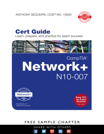
CHAPTER 2 INSTALLATIONPrecautionsPRECAUTIONSStatic Electricity GuardYou must wear a grounded wrist strap to protect circuit cards from static electricity.Figure 2-1 Static Electricity Guard (1 of 2) WHEN PLUGGING/UNPLUGGING A CIRCUIT CARDPBXFRAME GROUND SCREWWRIST STRAP WHEN HOLDING A CIRCUIT CARDNEVER TOUCH THE COMPONENTS ORSOLDERED SURFACE WITH BARE HANDS.CARD FRONTPage 18NEAX2000 IVS2 Remote PIM System ManualND-70917 (E), Issue 1.0
CHAPTER 2 INSTALLATIONPrecautionsFigure 2-1 Static Electricity Guard (2 of 2) WHEN MAKING A SWITCH SETTING ON A CIRCUIT CARDCIRCUITCARDWEAR A WRIST STRAP AND PERFORMTHE WORK ON A GROUNDEDCONDUCTIVE WORK SURFACE. WHEN CARRYING A CIRCUIT CARDCIRCUITCARDCONDUCTIVEPOLYETHYLENEBAGWHEN CARRYING A CIRCUIT CARDAROUND, KEEP THE CARD IN ACONDUCTIVE POLYETHYLENE BAG.The mark shown below is attached to the sheet for the work in which circuit cards are handled.When engaging in such work, the installer must be careful not to cause damage by static electricity.ATTENTIONContentsStatic SensitiveHandlingPrecautions RequiredNEAX2000 IVS2 Remote PIM System ManualND-70917 (E), Issue 1.0Page 19
CHAPTER 2 INSTALLATIONPrecautionsCAUTIONYou must hold the edge of a circuit card when plugging or unplugging the circuit card. If youtouch another area, you may be exposed to hazardous voltages.PBXNEVER TOUCH THE COMPONENTSOR SOLDERED SURFACE WITHBARE HANDS.CARD FRONTPage 20NEAX2000 IVS2 Remote PIM System ManualND-70917 (E), Issue 1.0
CHAPTER 2 INSTALLA
This manual explains the system outline and installation procedure for providing the Remote PIM to the NEAX2000 IVS2. USING THIS MANUAL This manual contains the following chapters: CHAPTER 1 GENERAL INFORMATION This chapter explains the outline of system configuration, required equipment, system capacity, system conditions, and time slot .