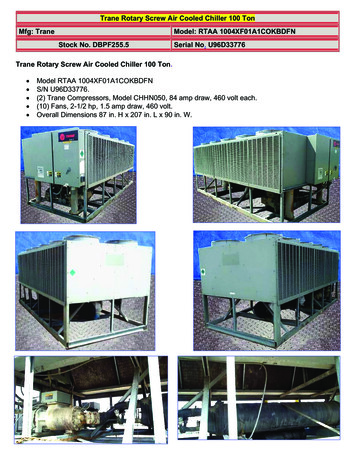
Transcription
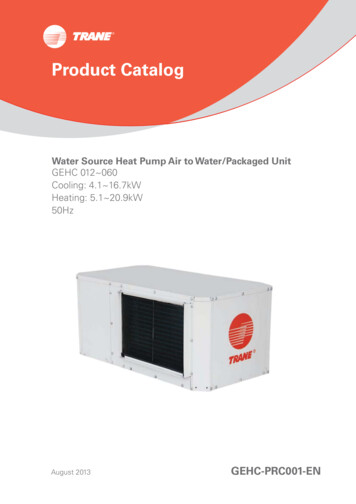
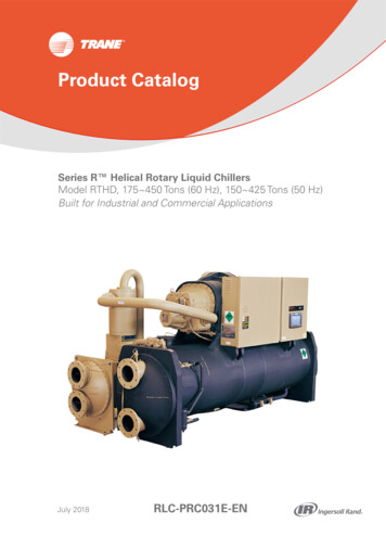
Product CatalogSeries R Helical Rotary Liquid ChillersModel RTHD, 175 450 Tons (60 Hz), 150 425 Tons (50 Hz)Built for Industrial and Commercial ApplicationsJuly 2018RLC-PRC031E-EN
IntroductionTo meet a wide range of applications in the medium-tonnage, water-cooled market,Trane isproud to recommend the model RTHD helical-rotary liquid chiller.This chiller provides applicationversatility, ease of installation, control precision, reliability, energy efficiency, and operational costeffectiveness.The RTHD chiller is designed to deliver proven performance, plus all the benefits of an advancedheat transfer design and a low speed, direct-drive compressorImportant Features High full-load energy efficiency reduces both operating and life-cycle costs. Tracer UC800 controls enable: scrolling access to inputs and operating information via the LCD touch-screen display freedom from interoperability concerns with LonMark and BACnet communications job-specific communication options that allow greater reporting flexibility Improved start up temperature capabilities and reduced sensitivity to condenser watertemperatures all eviate the most common startup concerns.The industrial-grade design of the helical-rotary chiller is ideal for both industrial and commercialmarkets, in applications such as office buildings, hospitals, schools, retail buildings, and industrialfacilities.The linear unloading compressor, wide operating temperature range, advanced controls,electronic expansion valve, short anti-recycle timers, and high efficiencies mean that thisTranechiller is the perfect choice for tight temperature control in almost any application temperatures,and under widely varying loads.2RLC-PRC031E-EN
Table of ContentsIntroduction 2Features and Benefits 4Controls 6Application Considerations 8Selection Procedure 10Model Nomenclature 12General Data 14Electrical Data and Connections 16Dimensions and Weights 19Mechanical Specifications 26ConversionTable 283RLC-PRC031E-EN
Features and BenefitsApplication Versatility and High Performance Screw compressor technology and the electronic expansion valveprovide reliable performance inan expanded range of operating temperatures. Tight water temperature control extends to operation of multiple chillers in parallel or seriesconfigurations, offering further system design flexibility for maximum efficiency. Advanced design enables chilled water temperature control to /- 0.5 F (.28 C) for flow changesup to 10 percent per minute, plus handling of flow changes up to 30 percent per minute forcomfort cooling. Two-minute stop-to-start and fiveminute start-to-start anti-recycle timer allows tight chilled watertemperature control in constant or transient lowload applications. LonMark communications capability provides excellent, trouble-free interoperability. Generic Building Automation System points are available for easy access to operationalinformation. Extensive information on professional design selection and layout is available in a simple, highlyreadable electronic format. Standard model RTHD configurations are in stock and available for immediate delivery, and Traneoffers the fastest ship cycles in the industry for built-to-order units. Industrial / Low Temperature Process Cooling – Excellent operating temperature range andprecise control capabilities enable tight control with single chiller or series configuration. Ice/Thermal Storage – Specifiers and operators benefit from dual setpoint control and industryleading temperature, efficiency, and control capabilities, plus outstanding support throughpartnership with Calmac, a strong Trane partner providing proven installation examples,templates, and references that minimize design time and energy costs.Simple, Economical Installation Compact size makes the model RTHD well suited for the retrofit and replacement market. All units fit through standard doublewidth doors. Bolt-together construction makes for fast, easy unit disassembly. Small RTHD footprint saves valuable equipment room space and alleviates access concerns formost retrofit jobs. Lightweight design simplifies rigging requirements, further reducing installation timerequirements and costs. Full factory refrigerant or nitrogen and oil charges reduce required field labor, materials, andinstallation cost. Only evaporator and condenser water piping is required; no starter water cooling (with itsassociated safety concerns) or field piping is necessary. Oil cooler and purge system connections have been eliminated. Simple power connection simplifies overall installation. Standard unit-mounted starter for Wye-Delta and Solid State eliminates additional jobsiteinstallation considerations and labor requirements. Trane has conducted extensive factory testing, and also offers options for in-person and/ordocumented system performance verification. Tracer AdaptiView TD7 control sinter face withTracer SC, LonTalk . BACnet or Modbus building automation systems.4RLC-PRC031E-EN
Features and BenefitsState-of-the-Art, Precision Control New 7 inch color touch screen display with graphics Powe redby UC800 industry-leadingcontrol algorithms Enhanced flow management provides unmatched system performance in variable flow watersystems Adaptive Control keeps the chiller running in extreme conditions Tight set point control Graphical trending Maximized chiller update BACnet ,Modbus ,LonTalk communications capability provides excellent, trouble-freeinteroperability. Generic Building Automation System points are available for easy access to operationalinformation. Advanced design enables chilled water temperature control to /-0.5 F(.28 C) for flow changesup to10 percent perminute, plus handling off low changes up to 30 percent per minute forcomfort cooling. Two-minutes top-to-start and five-minute start-to-start anti-recycle time rallows tight chilled watertemperature control in constant or transient low-load applications.Reliability and Ease of Maintenance Direct drive, low-speed compressor – a simple design with only three moving parts – providesmaximum efficiency, high reliability, and low maintenance requirements. Electronic expansion valve, with fewer moving parts than alternative valve designs, offers highlyreliable operation. Suction gas-cooled motor stays uniformly cool at lower temperatures for longer motor life. The Trane helical rotary compressor is a proven design resulting from years of research andthousands of test hours, including extensive testing under extraordinarily severe operatingconditions. Trane is the world’s largest manufacturer of large helical rotary compressors, with tens ofthousands of commercial and industrial installations worldwide demonstrating a reliability rate ofgreater than 99 percent in the first year of operation.Operating and Life Cycle Cost-Effectiveness Electronic expansion valve enables exceptionally tight temperature control and extremely lowsuperheat, resulting in more efficient full-load and part-load operation than previously available. Precise compressor rotor tip clearance ensures optimal efficiency. Condenser and evaporator tubes use the latest heat transfer technology for increased efficiency. The RTHD includes optional electrical demand limiting. Chilled water reset based on return water temperature is standard. High compressor lift capabilities and tight chilled water temperature control allow highly efficientsystem design with minimal operational concerns. Heat recovery option includes partial load and full load heat recovery. For traditional water-cooledchillers, heating capacity is exhausted into air, the heating recovery option allows to recoverypartial or total heating capacity for occasion that hot water needed.Design capabilities include: variable primary flow; series chiller arrangements for evaporator and/or condenser; low evaporator and condenser flow.5RLC-PRC031E-EN
ControlsTracer AdaptiView TD7 Operator InterfaceThe standard Tracer Adaptiview TD7 display provided with the Tracer UC800 controller featuresa 7” LCD touch-screen, allowing access to all operational inputs and outputs.This is an advancedinterface that allows the user to access any important information concerning setpoints, activetemperatures, modes, electrical data, pressure, and diagnostics. It uses full text display available in26 languages.Display Features Include: LCD touch-screen with LED backlighting, for scrolling access to input and output operatinginformation Single-screen, folder/tab-style display of all available information on individual components(evaporator, condenser, compressor, etc.) Manual override indication Password entry/lockout system to enable or disable display Automatic and immediate stop capabilities for standard or immediate manual shutdown Fast, easy access to available chiller data in tabbed format, including: Easy to view Operating Modes Logical Sub-Component Reports: Evaporator Condenser Compressor Motor 3 User Programmable Custom Reports ASHRAE report Logsheet Report Alarms Report 8 pre-defined Standard Graphs 4 User Programmable Custom Graphs Chiller Settings Feature Settings ChilledWater Reset Manual Control Settings Globalization Settings Support of 26 languages Brightness Setting Cleaning ModeTracer SCThe Tracer SC system controller acts as the central coordinator for all individual equipmentdevices on aTracer building automation system.The Tracer SC scans all unit controllers to updateinformation and coordinate building control, including building subsystems such as VAV and chillerwater systems. With this system option, the full breadth ofTrane’s HVAC and controls experienceare applied to offer solutions to many facility issues.The LAN allows building operators to managethese varied components as one system from any personal computer with web access.The benefits of this system are: Improved usability with automatic data collection, enhanced datalogging, easier to creategraphics, simpler navigation, pre-programmed scheduling, reporting, and alarmlogs. Flexible technology allows for system sizes from 30-120 unit controllers with any combination ofLonTalk or BACnet unit controllers. LEED certification through site commissioning report, energy data collection measurement,optimizing energy performance, and maintaining indoor air quality. Energy savings programs include: fan pressure optimization, ventilationreset, and chiller plantcontrol (adds and subtracts chillers to meet cooling loads).LonTalk Interface6RLC-PRC031E-EN
ControlsLonTalk communications capabilities are available, with communication link via single twisted-pairwiring.Additional options that may be used: Ice making and chilled water temperature reset - outdoor airExternal devices required: LonTalk system compatible interface.LonTalk Chiller ControlsLonTalk is a communications protocol developed by the Echelon Corporation.The LONMARK association develops control profiles using the LonTalk communication protocol. LonTalk is a unitlevel communications protocol.LonTalk Communications Interface for Chillers (LCI-C) provides a generic automation system withthe LONMARK chiller profile inputs/outputs. In addition to the standard points,Trane provides othercommonly used network output variables for greater interoperability with any automation system.Thecomplete reference list of Trane LonTalk points is available on the LONMARK web site.Trane controls or another vendor’s system can use the predefined list of points with ease to givethe operator a complete picture of how the system is running.BACnet InterfaceBACnet communications capabilities are available, with communication link via single twisted-pairwiring.Additional options that may be used: Ice making and chilled water temperature reset - outdoor airExternal devices required: BACnet MS/TP network.BACnet Chiller ControlsBACnet is an open standard communications protocol used by building automation systems.BACnet MS/TP uses RS-485 hardware.This device is a non-programmable communication modulethat connections directly to the UC800 chiller control.Modbus InterfaceTracer AdaptiView control can be configured for Modbus communications at the factory or inthe field.This enables the chiller controller to communicate as a slave device on a Modbusnetwork.Chiller setpoints, operating modes, alarms, and status can be monitored and controlled by aModbus master device.Hardwire PointsRemote devices wired from the control panel are another reliable method of providing auxiliarycontrol to a building automation system. Inputs and outputs can be communicated via a typical 4–20 mA electrical signal, an equivalent 2–10 Vdc signal, or by utilizing contact closures.Selectable options: External chilled water setpoint, external current-limit setpoint Condenser leaving hotwater temperature control setpoint (availableonunits with wye-deltastarters) Ice making control (available on units with wye-delta starters) Chilled water temperature reset Condenser pressure output Motor current analog output Programmable relays available outputs are: alarm-latching, alarm-auto reset, general alarm,warning, chiller limit mode, compressor running, head pressure relief request, and Tracer control7RLC-PRC031E-EN
Application ConsiderationsCondenser Water TemperaturesReduced sensitivity to condenser water startup temperatures is one major enhancement in thenewest-generation water-cooled Series R chiller. With the model RTHD chiller, a condenser watercontrol method is necessary only if the unit starts with entering water temperatures below 55 F(12.8 C), or between 45 F (7.2 C) and 55 F (12. 8 C), when a temperature increase of 1 F (0.56 C)per minute to 55 F (12. 8 ) is not possible.When the application requires startup temperatures below the prescribed minimums, a variety ofoptions are available. To control a 2-way or 3-way valve, Trane offers a Condenser Regulating ValveControl option for the UC800 controls. This option enables the UC800 controls to send a signalfor opening and closing the valve as necessary to maintain chiller differential pressure. The 2-wayvalves are available as a ship-with option. Tower bypass is also a valid control method if the chillertemperature requirements can be maintained.Trane Series R chillers start and operate successfully and reliably over a range of load conditionswith controlled entering condenser water temperature. Reducing the condenser water temperatureis an effective method of lowering chiller power input required, but the ideal temperature foroptimizing total system power consumption will depend on the overall system dynamics. From asystem perspective, some improvements in chiller efficiency may be offset by the increased towerfan and pumping costs required to achieve the lower tower temperatures. Contact your local Tranesystems solution provider for more information on optimizing system performance.The minimum acceptable refrigerant pressure differential between condenser and evaporator is23 psid. The chiller control system will attempt to obtain and maintain this differential at startup,but for continuous operation a design should maintain a 25 F (13. 9 C) differential from evaporatorleaving water temperature to condenser leaving water temperature.Variable Evaporator Flow and Short Evaporator Water LoopsVariable evaporator flow is an energysaving design strategy which has quickly gained acceptanceas advances in chiller and controls technology have made it possible. With its linear unloadingcompressor design and advanced UC800 controls, the RTHD has excellent capability to maintainleaving water temperature control within /-0.5 F (0.28 C) , even for systems with variableevaporator flow and small chilled water volumes.Some basic rules should be followed whenever using these system design and operational savingsmethods with the RTHD. The proper location of the chilled water temperature control sensor is inthe supply (outlet) water.This location allows the building to act as a buffer, and it assures a slowly changing return watertemperature. If there is insufficient water volume in the system to provide an adequate buffer,temperature control can be lost, resulting in erratic system operation and excessive compressorcycling. To ensure consistent operation and tight temperature control, the chilled water loopshould be at least two minutes. If this recommendation cannot be followed, and tight leavingwater temperature control is necessary, a storage tank or larger header pipe should be installed toincrease the volume of water in the system.For variable primary flow applications, the rate of chilled water flow change should not exceed 10percent of design per minute to maintain /-0.5 F (0.28 C) leaving evaporator temperature control.For applications in which system energy savings is most important and tight temperature controlis classified as /-2 F (1.1 C), up to 30 percent changes in flow per minute are possible. Flowrates should be maintained between the minimum and maximum allowed for any particular chillerconfiguration.8RLC-PRC031E-EN
Application ConsiderationsSeries Chiller ArrangementsAnother energy-saving strategy is to design the system around chillers arranged in series, onthe evaporator, condenser, or both. The actual savings possible with such strategies depends onthe application dynamics and should be researched by consulting your Trane Systems SolutionsRepresentative and applying the Trane System Analyzer program. It is possible to operate a pairof chillers more efficiently in a series chiller arrangement than in a parallel arrangement. It is alsopossible to achieve higher entering-to-leaving chiller differentials, which may, in turn, provide theopportunity for lower chilled water design temperature, lower design flow, and resulting installationand operational cost savings. The Trane screw compressor also has excellent capabilities for “lift,” which affords an opportunity for savings on the evaporator and condenser water loops. Likeseries arrangements on the evaporator, series arrangements on the condenser may enablesavings. This approach may allow reductions in pump and tower installation and operating costs.Maximizing system efficiency requires that the designer balance performance considerationsfor all system components; the best approach may or may not involve multiple chillers, or seriesarrangement of the evaporators and/or condensers. This ideal balance of design integrity withinstallation and operating cost considerations can also be obtained by consulting a Tranerepresentative and applying the Trane System Analyzer program.Water TreatmentThe use of untreated or improperly treated water in chillers may result in scaling, erosion,orrosion, and algae or slime buildup. It is recommended that the services of a qualified watertreatment specialist be engaged to determine what treatment, if any, is advisable. Trane assumesno responsibility for the results of using untreated or improperly treated water.Water PumpsWhere noise limitation and vibrationfree operation are important, Trane strongly encourages theuse of 1750-rpm (60 Hz), 1450-rpm (50 Hz) pumps.Specifying or using 3600-rpm (60 Hz), 3000-rpm (50 Hz) condenser water and chilled waterpumps must be avoided, because such pumps may operate with objectionable levels of noise andvibration. In addition, a low frequency beat may occur due to the slight difference in operating rpmbetween 3600-rpm (60 Hz), 3000-rpm (50 Hz) water pumps and Series R chiller motors. ImportantNote: The chilled water pump must not be used to stop the chiller.Acoustic ConsiderationsFor chiller sound ratings, installation tips, and considerations on chiller location, pipe isolation, etc.,refer to the Trane Water-Cooled Series R Chillers Sound Ratings and Installation Guide.Using the information provided in this bulletin, contact a certified sound consultant to aid in propermechanical room design and treatment.9RLC-PRC031E-EN
Selection ProcedureTrane Series R chiller performance is rated in accordance with the ARI Standard 550/590-2003Certification Program. Chiller selection assistance and performance information can be obtained byusing the Series R chiller selection program, available through local Trane sales offices.PerformanceThe computerized Series R chiller selection program provides performance data for each possiblechiller selection at both full-load and part-load design points, as required.It should be noted that changing the number of water passes or the water flow rates will generallyalter the performance of a particular chiller. To attain maximum benefit from the wide range ofchiller models and options available, designers are encouraged to first develop performancespecifications and then use the chiller selection program to optimize all selections. This will helpensure selection of the compress or evaporator - condenser combination that most closely meetsthe job requirements. To optimize system performance, all selections should also be balanced withother system components.Fouling FactorsARI Standard 550 includes a definition of clean tube fouling. The recommended standard foulingadjustments are 0.0001 hr-sq ft-deg F/Btu (0.0176 sq m-deg C/kW) for the evaporator and 0.00025hr-sq ft deg F/Btu (0.044 sq m-deg C/kW) for the condenser, from an increment of 0.0000 “clean.”Chiller specifications should be developed using the most current standard fouling factors.Part Load PerformanceActual air-conditioning system loads are frequently less than full-load design conditions. Dependingon the number of chillers on the job and the load profile, chillers may operate at full load a smallpercentage of the time. With their excellent part-load performance characteristics and highlyenergy efficient operation, Series R chillers can provide significant operating savings at these partload conditions, maximum down to 20%.System ConsiderationsPart-load chiller operation is frequently associated with reduced condenser water temperatures.However, rather than focusing only on the chiller, it is important to balance these temperatures toachieve the most efficient system operation possible. At part-load operation, the heat rejected tothe cooling tower is less than at fullload operation.Part-load chiller operation is also typically associated with reduced outside wet bulb temperatures,resulting in improved cooling tower performance. The net result of reduced heat rejection andlower wet bulb temperatures can be cooler condenser water entering the chiller, ultimatelyimproving unit performance. However, this does not improve pump or tower efficiency. To achievethe most efficient system operation possible, it is best to minimize the total power draw of thechiller, tower, and pumps, which may not mean limiting the condenser water temperature to whatthe tower can provide. To determine specific unit and system part-load performance for chillerselection purposes, use the Series R chiller computer selection program or contact the local Tranesales office.10RLC-PRC031E-EN
Selection ProcedureUnit Performance with Fluid Media Other Than WaterSeries R chillers can be provided with awide variety of fluid media other than water, includingethylene glycol and propylene glycol— in the evaporator, condenser or both. Chillers using mediaother than water are excluded from the ARI 550/590-2003 Certification Program, but are rated inaccordance with ARI Standard 550/590-2003. Trane factory performance tests are only performedwith water as the cooling and heat-rejection media. When considering selection of media otherthan water, contact the local Trane sales office for chiller selections and factory performancetesting information.Fluid media other than water lowers the heat transfer coefficient, and therefore reduces chillerperformance.In general, it is good practice to hold the percent glycol added to within the minimum allowed bythe Trane selection program, based on either (a) unit operating temperatures, or (b) the operatingtemperatures the evaporator or condenser water will experience under its full range of conditions.Adding more glycol than required for the specific application is equivalent to selecting a lessefficient chiller. Lower viscosity glycols such as ethylene will have less adverse impact on chillerperformance than higher-viscosity glycols such as propylene.Evaporator and Condenser Pressure DropPressure drop data is determined by the Series R chiller computer selection program availablethrough local Trane sales offices.Dimensional DrawingsDimensional drawings provided for selection purposes illustrate overall measurements of the unit.The recommended service clearances are those required to easily service the Series R chiller.All catalog dimensional drawings are subject to change, and current submittal drawings shouldbe referenced for more detailed dimensional information. Dimensional drawings are also availablefrom the selection program. Contact the local Trane sales office for submittal information.Electrical Data TablesCompressor motor electrical data is provided in the data section for each compressor size. Ratedload amperes (RLA), locked rotor wye amperes (LRA) and expected inrush for the Wye-delta andSolid State Starter configurations are shown.Although the terms “LRA” and “expected inrush” are often used interchangeably, the distinctionapplied here is that LRA is the rated inrush for the motor, but expected inrush is that allowed bythe starter, based on the specific configuration.Selecting starters in the Wye-delta or Solid State configuration lowers expected inrush vs. theDelta (or “across-the-line”) configuration. A Solid State Starter configuration lowers the expectedinrush by approximately 50 percent, while Wye-Delta lowers it by approximately 66 percent.The RLA is based on the motor’s performance when reaching full rated horsepower. The kWrating of the motor will equal or exceed the kW requirement indicated by the Series R computerselection program at design conditions. If motor kW draw at design conditions is less than thekW rating of the motor, the RLA at design conditions is determined by multiplying the motor RLA(at the desired voltage) by this ratio: design kW/motor kW rating. This calculation is performedwithin the Series R chiller computer selection program, making RLA available as part of the designpredictions. Predicted values include power factor variation from point to point.A voltage utilization range is tabulated for each voltage listed. Series R chillers are designed tooperate satisfactorily over a utilization range of 10 percent of the standard design voltages: 380 V,415 V for 50 Hertz, 3-phase.11RLC-PRC031E-EN
Model NomenclatureR T H D C B 1 R X A 0 X L B 1 A 3 L A L B 1 A 2 L A L A X X1 2 3 4 5 6 7 8 9 10 11 12 13 14 15 16 17 18 19 20 21 22 23 24 25 26 27 28 29 30Digit 1-4 Basic Product LineRTHD Water-cooled Series RDigit 5 Manufacturing PlantU Water Chiller Business Unit,Pueblo CO USAE Epinal Business Unit, CharmesE China Business UnitDigit 6-7 CompressorB1 B1 compressorB2 B2 compressorC1 C1 compressorC2 C2 compressorD1 D1 compressorD2 D2 compressorD3 D3 compressor (50HZ only)E3 E3 compressor (50HZ only)Digit 8 Unit Power SupplyC 230V/60Hz/3Ph powerD 380V/60Hz/3PhpowerR 380V/50Hz/3PhpowerT 400V/50Hz/3PhpowerU 415V/50Hz/3Ph powerF 460V/60Hz/3PhpowerDigit 9 Design SpecialsX NoneC Specials denoted elsewhereS Specials not denoted elsewhereDigit 10-11 Design SequenceA0 Factory/ABU assigned, startwithA0Digit 12 Agency ListingX No agency listingU C/UL listing3 CCC-Chinese Compulsory CodeDigit 13 Pressure Vessel CodeA ASME pressure vessel codeC Canadian codeL Chinese codeS SpecialDigit 14-15 EvaporatorB1 B1 evaporatorB2 B2 evaporator12C1 C1 evaporatorC2 C2 evaporatorD1 D1 evaporatorD2 D2 evaporatorD3 D3 evaporatorD4 D4 evaporatorD5 D5 evaporatorE1 E1 evaporatorF1 F1 evaporatorF2 F2 evaporatorG1 G1 evaporatorG2 G2 evaporatorG3 G3 evaporatorF3 F3 condenserH1 H1 condenser heat recovery coilH2 H2 condenser heat recovery coilJ1 J1 condenser heat recovery coilJ2 J2 condenser heat recovery coilJ3 J3 condenser heat recovery coilK1 K1 condenser heat recovery coilL1 L1 condenser heat recovery coilL2 L2 condenser heat recovery coilM1 M1 condenser heat recovery coilM2 M2 condenser heat recovery coilM3 M3 condenser heat recovery coilN1 N1 condenser heat recovery coilDigit 16 Evap Tube typeA StandardDigit 23 Condenser Tube TypeA Enhanced fin-copperB Smooth bore-copperC Smooth bore-90/10 Cu/NiDigit 17 Evaporator Passes2 2 pass evaporator3 3 pass evaporator4 4 pass evaporatorDigit 24 Condenser Passes2 2 passDigit 18 Evaporator WaterConnectionL Left hand evaporator connectionR Right hand evaporatorconnectionDigit 25 Condenser WaterConnectionL Left hand evaporator connectionR Right hand evaporatorconnectionDigit 19 Evaporator Connection TypeA Standard flange connectionS SpecialDigit 26 Condenser Connection TypeA Standard flange connectionC MarineS SpecialDigit 20 Evaporator Water SidePressureL 150PSI/10.5Bar evaporator waterpressureH 300PSI/21Bar evaporator waterpressureDigit 21-22 CondenserB1 B1 condenserB2 B2 condenserD1 D1 condenserD2 D2 condenserE1 E1 condenserE2 E2 condenserE3 E3 condenserE4 E4 condenserE5 E5 condenserF1 F1 condenserF2 F2 condenserDigit 27 Condenser Water SidePressureL 150PSI/10.5Bar evaporator waterpressureH 300PSI/21Bar evaporator waterpressureDigit 28 Condenser Leaving WaterTempA Standard ( 45 deg C)Digit 29 Refrigerant SpecialtiesX No refrigerant isolation valvesV Refrigerant isolation valvesDigit 30 Oil CoolerX without oil coolerC with oil coolerRLC-PRC031E-EN
Design SequenceQ X C X A A B X Y 1 7 4 A A X H X X X X X X X X X X X31 32 33 34 35 36
In addition to the standard points,Trane provides other commonly used network output variables for greater interoperability with any automation system.The complete reference list of Trane LonTalk points is available on the LONMARK web site. Trane controls or another vendor's system can use the predefined list of points with ease to give