Transcription
100303268 2000556051 Rev ACommercial ElectricWater HeaterInstallation & ServiceManualModels: 0150 - 1000 WARNING: If the information in thismanual is not followed exactly, a fire orexplosion may result causing property damage,personal injury, or loss of life.HLW WARNINGThis manual must only be usedby a qualified heating installer/service technician. Read allinstructions, including thismanual,beforeinstalling.Perform steps in the order given.Failure to comply could result insevere personal injury, death, orsubstantial property damage.Save this manual for future reference.
ContentsHAZARD DEFINITIONS . 2PLEASE READ BEFORE PROCEEDING . 3INTRODUCTION . 4RATINGS . 51. FEATURES AND COMPONENTSVertical Models . 6Horizontal Models. 7Dimensions and Capacities Data . 8-92. DETERMINE WATER HEATER LOCATIONFacts to Consider About the Location . 10-113. INSTALLATIONMixing Valve Usage . 12Chemical Vapor Corrosion . 12Circulating Pump . 12Insulation Blankets . 12Temperature - Pressure Relief Valve.12-13Closed Water Systems. 13Thermal Expansion . 134. ELECTRICALGeneral. 14Branch Circuit . 14Heater Circuits. 14Power Circuit . 14Amp Chart . 15-16Electrical and Recoveries Data . 17208V - 240V Chart . 185. OPERATIONGeneral. 19Filling the Water Heater . 19Initial Start-up . 19Draining the Water Heater . 196. TEMPERATURE REGULATIONHigh Temperature Limit Controls (ECO) . 20Thermostat Controls . 20Temperature Adjustment . 207. CONTROL SYSTEM OPERATIONHeating Banks Operation . 21Control System Features . 21Control System Navigation. 21The Display Screen . 21Control System Operation Tables . 22-23Temperatures Menu . 24Temperature Screens . 25Water Heater Status Menu . 26Economy Mode Setup Menu . 27Economy Mode Settings Tables . 28-30Alarm Output Setup Menu . 31Display Settings Menu . 31Heater Information Menu . 32Current Fault / Alert Menu. 32Fault History Menu . 32Fault Occurrence Menu. 33Restore Factory Defaults Menu . 348. MAINTENANCEGeneral. 35Anode Rod Inspection . 35Flushing the Water Heater . 35Sediment Removal . 36Lime Scale Removal . 369. TROUBLESHOOTINGChecklist . 3710. DIAGRAMSWiring Diagram . 38-39Revision Notes . Back CoverHazard definitionsThe following defined terms are used throughout this manual to bring attention to the presence of hazards of various risk levels orto important information concerning the life of the product. DANGERDANGER indicates an imminently hazardous situation which, if not avoided, will result in death or seriousinjury.WARNING indicates a potentially hazardous situation which, if not avoided, could result in death or serious WARNING injury.CAUTION indicates a potentially hazardous situation which, if not avoided, may result in minor or moderate CAUTION injury.CAUTIONCAUTION used without the safety alert symbol indicates a potentially hazardous situation which, if notavoided, may result in property damage.NOTICENOTICE indicates special instructions on installation, operation, or maintenance that are important but notrelated to personal injury or property damage.2
Please read before proceeding WARNINGInstaller – Read all instructions beforeinstalling. Perform steps in the ordergiven.Have this water heater serviced/inspectedby a qualified service technician, at leastannually.Failure to comply with the above couldresult in severe personal injury, death, orsubstantial property damage.NOTICEWhen calling or writing about the waterheater – Please have the water heatermodel and serial number from the waterheater rating plate.Consider piping and installation whendetermining water heater location.Any claims for damage or shortage inshipment must be filed immediatelyagainst the transportation company by theconsignee.Factory warranty (shipped with unit) doesnot apply to units improperly installed orimproperly operated. WARNINGFailure to adhere to the guidelines on thispage can result in severe personal injury,death, or substantial property damage. WARNING If the information in this manual is notfollowed exactly, a fire or explosion mayresult causing property damage, personalinjury, or loss of life. WARNINGThe California Safe Drinking Water andToxic Enforcement Act requires theGovernor of California to publish a list ofsubstances known to the State of Californiato cause cancer, birth defects, or otherreproductive harm, and requires businessesto warn of potential exposure to suchsubstances.This product contains a chemical known tothe State of California to cause cancer, birthdefects, or other reproductive harm. Thiswater heater can cause low level exposureto some of the substances listed in the Act.When servicing the water heater – To avoid electric shock, disconnect electrical supplybefore performing maintenance. To avoid severe burns, allow the water heater to coolbefore performing maintenance. Do not use this water heater if any part has been underwater. The possible damage to a flooded appliance canbe extensive and present numerous safety hazards. Anyappliance that has been under water must be replaced.Grounding Instructions – This water heater must be grounded in accordancewith the National Electrical Code and/or local codes.These must be followed in all cases. Failure to groundthis water heater properly may also cause erraticcontrol system operation on ELECTRONICCONTROL models. This water heater must be connected to a groundedmetal, permanent wiring system, or an equipmentgrounding conductor must be run with the circuitconductors and connected to the equipment groundingterminal or lead on the water heater.Hydrogen Gas (Flammable) –Hydrogen gas can be produced in a hot water system,served by this heater, that has not been used for a longperiod of time (generally two weeks or more). Hydrogengas is extremely flammable. To reduce the risk of injury,it is recommended that the hot water faucet be openedfor several minutes at the kitchen sink before using anyelectrical appliance connected to the hot water system.If hydrogen is present, there will probably be an unusualsound, such as air escaping through the pipe as waterbegins to flow. WARNINGThere should be no smoking or openflame near the faucet at the time itis open. WARNINGFlammable hydrogen gases may bepresent. WARNINGKeep all ignition sources away fromfaucet when turning on hot water.3
IntroductionThank you for purchasing this water heater. Properly installedand maintained, it should give you years of trouble-freeservice.Abbreviations UsedAbbreviations found in this instruction manual include: ANSI - American National Standards Institute ASME - American Society of Mechanical Engineers NEC - National Electrical Code NFPA - National Fire Protection Association UL - Underwriters Laboratory CSA - Canadian Standards Association AHRI - Air Conditioning, Heating, & RefrigerationInstitutePreparing for the Installation WARNINGBefore removing any access panelsor servicing the water heater, makesure the electrical supply to the waterheater is turned OFF. Failure to dothis could result in death, seriousbodily injury, or property damage.Read the Please read before proceeding. section of this manualfirst, then read the entire manual carefully. If you don’t followthe safety rules, the water heater may not operate safely, whichcould result in death, serious bodily injury, and/or propertydamage.This manual contains instructions for the installation,operation, and maintenance of the water heater. It alsocontains warnings throughout the manual that you mustread and be aware of. All warnings and all instructions areessential to the proper operation of the water heater and yoursafety. Read the entire manual before attempting to install oroperate the water heater.General outline diagrams are in this manual. These diagramswill serve to provide the installer with a reference for basicinstallation of this product. It is necessary that all water pipingand electrical wiring be installed and connected as shown inthe diagrams.Be sure to turn power OFF when working on or near theelectrical system of the water heater. Never touch electricalcomponents with wet hands or when standing in water. Whenreplacing fuses always use the correct size for the circuit. Usethe same size and type of fuse when replacing.Detailed installation diagrams are in this manual. Thesediagrams will serve to provide the installer with a reference forthe materials and method of piping suggested. It is necessarythat all water piping and electrical wiring be installed andconnected as shown in the diagrams.4The principle components of the heater are identified on pages6 and 7. The model and rating plate on page 5 interprets certainmarkings into useful information. Both of these referencesshould be used to identify the heater, its components, andoptional equipment.The installation must conform with these instructionsand the local code authority having jurisdiction and therequirements of the power company. In the absence of localcodes, the installation must comply with the current editionsof the National Electrical Code, NFPA 70 or the CanadianElectrical Code, CSA C22.1. The National Electrical Codemay be ordered from: National Fire Protection Association,1 Batterymarch Park, Quincy, MA 02269. The CanadianElectrical Code is available from the Canadian StandardsAssociation, 8501 East Pleasant Valley Road, Cleveland, OH44131.If after reading this manual you have any questions or do notunderstand any portion of the instructions, call the telephonenumber on the back cover for further assistance. Please havethe model and serial number of the unit available for thetechnician.Carefully plan your intended placement of the water heater.Examine the location to ensure the water heater complies withthe Determine Water Heater Location section in the manual.Clearance must be maintained so that the heating elementsmay be removed for servicing after installation.Installation and service of this water heater requires abilityequivalent to that of a licensed tradesman or qualified agencyin the field involved. Plumbing and electrical work arerequired.For installation in California, this water heater must be bracedor anchored to avoid falling or moving during an earthquake.See instructions for correct installation procedures.Instructions may be obtained from the California Office ofthe State Architect, 1102 Q Street, Suite 5100, Sacramento,CA 95811.Massachusetts Code requires this water heater to be installedin accordance with Massachusetts 248-CMR 2.00: StatePlumbing Code and 248-CMR 5.00.
RatingsHLWAll models are listedby UnderwritersLaboratories Inc.Rating & Model Plate 5,ELECTRIC STORAGETANK WATER HEATER Kt KEd Ed MODEL NUMBER SERIAL NUMBERVOLTS, ACPHASEKILOWATTSUPPERVOLTS, ACKILOWATTSUPPERKILOWATTSLOWERTOTAL kWCONNECTEDKILOWATTSLOWERLISTED932NITEM ID/PART NUMBERCAPACITYUS GALLONSTOTAL kWCONNECTEDMAX WORKINGPRESSURECIRCUITADDRESSSERIAL NUMBER BARCODEMODEL NUMBER BARCODESERIAL NUMBER 123456789MODEL NUMBER XXXXXXXXLE 123456ASM CERTIFIED BY LCE MAWP XXX PSIMAX ALLOWABLE INPUTHLW XXXXXXXXX BTU/HRS/N123456789YEAR BUILT YYWWCRN XXXXXXXXXXXXXXXXXXXX5
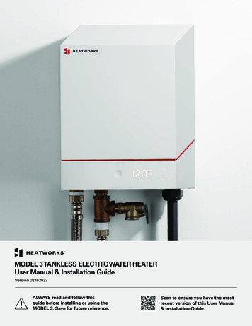
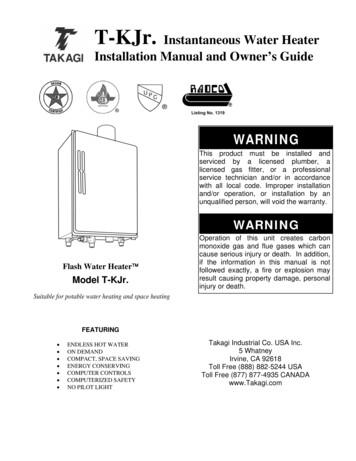
1Features and ComponentsVertical ModelsNote: Model shown for illustration purposes only. Actual configurations may vary.6
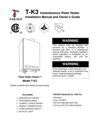
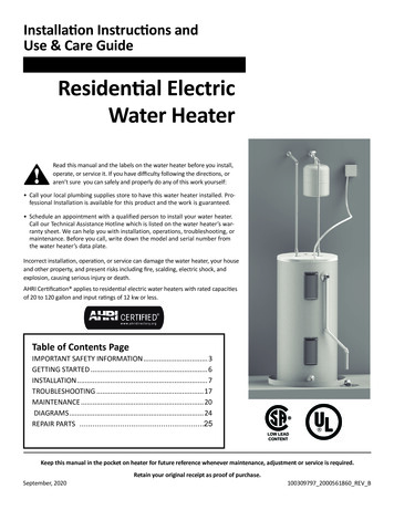
1Features and ComponentsHorizontal ModelsCONTROLLERRELIEF VALVETRANSFORMER (CONTROLLER)ANODEMAIN VOLTAGE GROUND LUGPOWER BLOCKMAIN VOLTAGE FUSE & BLOCKHANDHOLE/MANWAYACCESSLOW VOLTAGE FUSE & BLOCKMAIN VOLTAGE TRANSFORMERLOW WATER CUT OFF PROBETEMPERATURE PROBEPLUGELEMENTSCONTACTORSHIGH LIMITLOW VOLTAGE FUSE & BLOCKLOW VOLTAGE GROUND LUGNote: Model shown for illustration purposes only. Actual configurations may vary.7
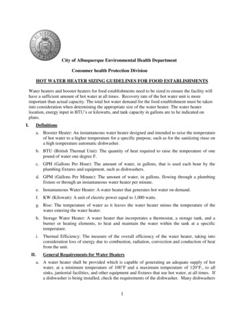
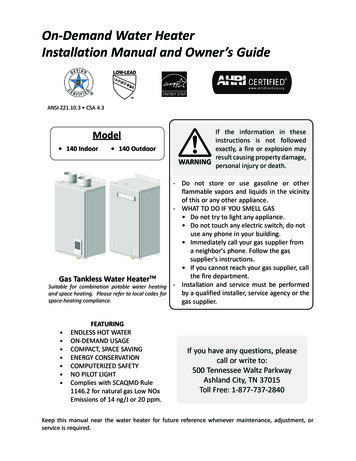
1Features and ComponentsSpecifications DataB3/4"T&PRELIEFVALVECONNECTIONHOT WATEROUTLETADDITIONALHEIGHT IFREQUIREDELECTRONICCONTROL3/4" OR 1" DRAINCONTROL VOLTAGEON/OFF SWITCHCACOLD WATERINLETCLEANOUTHINGED DOORTO ELECTRICALCOMPARTMENTDDRAINTOP VIEWCHANNEL (150 & 200 GALLON DO NOT HAVE CHANNELS)BHOT WATEROUTLET6.688T&P RELIEF VALVECADDITIONALHEIGHT IFREQUIREDELECTRONICCONTROLHANDHOLE4.000CONTROL VOLTAGEON/OFF SWITCHINLETDA & D ELEVATION FROM FINISHED FLOOR8DRAINEXTRA PANEL BOX MAY BE NECESSARY FOR INPUTSHIGHER THAN 72KW. CONSULT FACTORY.
1Features and ComponentsSpecifications ConnectionOutlet WaterConnectionShippingWeight (lbs)11 3/4"1 1/2"1 1/2"65038 3/4"11 3/4"1 1/2"1 1/2"75040 3/4"19 1/4"1 1/2"1 1/2"1,16540"46 3/4"20 3/4"2"2"1,35046"52 3/4"22 1/4"2"2"1,59091 3/8"46"52 3/4"22 1/4"2"2"1,70092 5/8"52"58 3/4"24 1/4"2 1/2"2 1/2"2,010432104"52"58 3/4"24 1/4"2 1/2"2 1/2"2,450486128"52"58 3/4"24 1/4"2 1/2"2 1/2"3,160Maximum KWInputHeightA015016265 1/2"32"38 3/4"020021678"32"025027091 odelDepthCDVERTICAL ROUND ELECTRIC STORAGE HEATERVERTICAL SQUARE ELECTRIC STORAGE HEATER1250648132 1/2"64 1/2"64 1/2"23 1/4"3"3"3,5601500918128 1/2"70 1/2"70 1/2"25 1/4"3"3"4,1202000918140 1/2"76 1/2"76 1/2"27 1/4"3"3"4,3502500918146 1/2"82 1/2"82 1/2"29"3"3"5,750HORIZONTAL SQUARE ELECTRIC STORAGE HEATER015016237"68 1/2"34 1/4"12"2"2"1,1800200198025024037"78"34 1/4"12"2"2"1,37039"90 1/4"36 1/4"13"2"2"03001,45030045"78 1/4"42 1/4"14 3/4"2"2"1,530040032452"78 1/4"48 1/4"16"2"2"1,750050043252"90 3/4"48 1/4"16"2"2"1,860060041458"90 3/4"54 1/4"13 1/2"2 1/2"2"2,340080046858"102 1/4"54 1/4"13 1/2"2 1/2"2"2,850100064858"126 1/4"54 1/4"13 1/2"2 1/2"2"3,040125064864"130 1/4"60 1/4"15"3"3"3,750150091870"126 1/4"66 1/4"16"3"3"4,340200091876"137 1/4"72 1/4"17 1/2"3"3"4,580250091882"144 1/4"78 1/4"16 1/2"3"3"6,0609
2Determine Water Heater LocationDetermine Water Heater LocationCAUTIONAll water heaters eventually leak. Donot install without adequate drainage.Hot water piping and branch circuit wiring should be as short aspossible. Insulate hot and cold water piping where heat loss andcondensation may be a problem.Carefully choose a location for the new water heater. Theplacement is a very important consideration for the safety of theoccupants in the building and for the most economical use ofthe appliance.Heater construction permits installation, maintenance, andservice work to be performed through the element box door andcontrol box door.Whether replacing an old water heater or putting the waterheater in a new location, the following critical points must beobserved. The water heater must be located:Suggested clearances from adjacent surfaces are 12 inches ontop, 30 inches in front of access doors, 24 inches for cleanout/handhole/manway side, and 6 inches on the inlet water pipingside.1.On a level surface. Shim the channel-type skid base asnecessary if leveling is required.2.Near a floor drain. The heater should be located in an areawhere leakage of the tank or connections will not result indamage to the area adjacent to the heater or to lower floorsof the structure. When such locations cannot be avoided, asuitable drain pan should be installed under the heater. Thepan should be at least 2 inches deep, have a minimum lengthand width of at least 2 inches greater than the dimensions ofthe water heater, and should be piped to an adequate drain.The discharge opening of the relief valve should always bepiped to an open drain.3.Close to the point of major hot water usage and the powersupply.10The heater may be installed on or against combustible surfaces.The back may be placed flush against adjacent surfaces. Be sureto place the cover plates over the rear crating couplings beforelocating vertical model heaters that were shipped laying down.The heater may be installed in a confined space if adequateventilation is provided.The temperature of the space in which the water heater isinstalled must not go below 320F or above 1220F.
2Determine Water Heater Location(continued) Figure 2-1 Clearances from Combustible ConstructionTOPCLEARANCE12"ACCESS DOORCLEARANCEREAR INLET WATERPIPINGCLEARANCEMANWAY ORHANDHOLECLEARANCE30" 6"24"RIGHTMANWAY ORHANDHOLECLEARANCEACCESS DOORCLEARANCE 36"24"FRONT LEFTFRONTCLEARANCE 12" REARACCESS DOORCLEARANCE *30"24" FRONT*DISTANCE FOR DOOR TO OPENMANWAY ORHANDHOLECLEARANCERIGHT11
3InstallationThe installation must conform to these instructions and localcode authority having jurisdiction. Grounding and electricalwiring connected to the water heater must also conform to theNational Electrical Code, NFPA 70. This publication is availablefrom The National Fire Protection Association, 1 BatterymarchPark, Quincy, MA 02269.CAUTIONDo NOT test electrical system beforeheater is filled with water. Follow theStart-up procedure in the Operationsection of this manual.The principle components of the heater are identified in theFeatures and Components illustration on pages 6 and 7. DANGERWater temperature over 1250F (520C)can cause severe burns instantly resultingin severe injury or death. Children, theelderly, and the physically or mentallydisabled are at highest risk for scaldinjury. Feel water before bathing orshowering. Temperature limiting devices,such as mixing valves, must be installedwhen required by code and to ensure safetemperatures at fixtures.Mixing Valve UsageWater heaters are intended to produce hot water. Water heated toa temperature which will satisfy clothes washing, dish washing,cleaning, and other sanitizing needs can scald and permanentlyinjure you upon contact. Some people are more likely to bepermanently injured by hot water than others. These include theelderly, children, the infirm, or the physically or developmentallydisabled. If anyone using hot water in your home fits into oneof these groups, or if there is a local code or state law requiring amaximum water temperature at the hot water tap, then you musttake special precautions. In addition to using the lowest possibletemperature setting that satisfies your hot water needs, a meanssuch as a mixing valve, should be used at the hot water taps or atthe water heater.Mixing valves for reducing point-of-use temperature areavailable. Consult a qualified installer or service agency. Followall manufacturer’s instructions for installation of mixing valves.Before changing the factory setting on the thermostat, read theTemperature Regulation section in this manual. WARNINGToxic chemical hazard: Do not connectto non-potable water system.Chemical Vapor CorrosionThis water heater shall not be connected to any heatingsystem(s) or component(s) used with a non-potable waterheating appliance. Toxic chemicals, such as those used for boilertreatment, shall not be introduced into this system. Water heatercorrosion and component failure can be caused by the heating andbreakdown of airborne chemical vapors. Spray can propellants,cleaning solvents, refrigerator and air conditioning refrigerants,swimming pool chemicals, water softener chemicals, calciumand sodium chloride, waxes, and process chemicals are typical12compounds which are potentially corrosive. These materialsare corrosive at very low concentration levels with little or noodor to reveal their presence. Products of this sort should notbe stored near the heater. Also, air which is brought in contactwith the water heater should not contain any of these chemicals.If necessary, uncontaminated air should be obtained fromremote or outside sources.Circulating PumpField-installed circulating pumps should be of all bronzeconstructions. To optimize the total storage capacity of ahorizontal vessel, particularly under low draw conditions, it isrecommended to utilize a pump and recirculation line sized toturn the entire storage capacity of the tank once each hour (i.e., a600 gallon tank would require a 10 gpm pump).Insulation BlanketsInsulation blankets are available to the general public forexternal use on electric water heaters, but are not necessary withthis product. The purpose of an insulation blanket is to reducethe standby heat loss encountered with storage tank heaters.Your water heater meets or exceeds the EPACT and ASHRAE/IES 90.1 standards with respect to insulation and standby lossrequirements, making an insulation blanket unnecessary.Should you choose to apply an insulation blanket to this heater,you should follow the instructions below. Failure to follow theseinstructions can result in fire, serious personal injury, or death. Do NOT cover the temperature and pressure relief (T & P)valve with an insulation blanket. Do NOT cover the instruction manual. Keep it on the sideof the water heater or nearby for future reference. DO obtain new warning and instruction labels for placementon the blanket directly over the existing labels.Temperature - Pressure Relief Valve WARNINGThe temperature and pressure reliefvalve must comply with ANSI Z21.22and ASME code. A properly sizedtemperature and pressure relief valvemust be installed in the openingprovided. Failure to install a reliefvalve can result in overheating andexcessive tank pressure. Failure tofollow these instructions can causeserious injury or death.This water heater is provided with a properly rated/sized andcertified combination temperature-pressure relief valve by themanufacturer. The valve is certified by a nationally recognizedtesting laboratory that maintains periodic inspection ofproduction of listed equipment of materials as meeting therequirements for Relief Valves for Hot Water Supply Systems,ANSI Z21.22 CSA 4.4, and the code requirements of ASME.
3Installation(continued)If replaced, the new valve must meet the requirements of localcodes, but not less than a combination temperature and pressurerelief valve rated/sized and certified as indicated in the aboveparagraph. The new valve must be marked with a maximum setpressure not to exceed the marked hydrostatic working pressureof the water heater (150 psi 1,035 kPa) and a discharge capacitynot less than the water heater Btu/hr or KW input rate as shownon the water heater’s model rating plate.For safe operation of the water heater, the temperature andpressure relief valve must not be removed from its designatedopening nor plugged. The temperature-pressure relief valvemust be installed directly into the fitting of the water heaterdesigned for the relief valve. Install discharge piping so thatany discharge will exit only within 6 inches (15.2 cm) above, orexternal to the structure. Do not pipe the discharge to a crawlspace. Be certain that no contact is made with any live electricalpart. The discharge opening must not be blocked or reducedin size under any circumstances. Excessive length, over 30 feet(9.14 m), or use of more than four elbows can cause restrictionand reduce the discharge capacity of the valve.No valve or other obstruction is to be placed between the reliefvalve and the tank. Do NOT connect discharge piping directlyto the drain unless a 6" (15.2 cm) air gap is provided. To preventbodily injury, hazard to life, or property damage, the relief valvemust be allowed to discharge water in adequate quantities,should circumstances demand. If the discharge pipe is notconnected to a drain or other suitable means, the water flow maycause property damage.The discharge pipe: Shall NOT be smaller in size than the outlet pipe size of thevalve or have any reducing couplings or other restrictions. Shall NOT be plugged or blocked. Shall NOT be exposed to freezing temperatures. Shall be of material listed for hot water distribution. Shall be installed in such a way that allows completedrainage of both the temperature-pressure relief valve andthe discharge pipe. Must terminate a maximum of six inches above a floordrain or external to the building. In cold climates, it isrecommended that the discharge pipe be terminated at anadequate drain inside the building. Shall NOT have any valve or other obstruction between therelief valve and the drain.CAUTIONThe temperature-pressure relief valvedischarge pipe must terminate at adequatedrain.The temperature-pressure relief valve must be manually operatedat least once a year. Caution should be taken to ensure thatno one is in front of or around the outlet of the temperaturepressure relief valve discharge line, and that the water manuallydischarged will not cause any bodily injury or property damagebecause the water may be extremely hot. If after manuallyoperating the valve, it fails to completely reset and continuesto release water, immediately close the cold water inlet to thewater heater, follow the draining instructions in this manual,and replace the temperature-pressure relief valve with a properlyrated/sized new one.If you do not understand these instructions or have anyquestions regarding the temperature-pressure relief valve, callthe telephone number listed on the back cover of this manual fortechnical assistance.Water temperature over 1250F (520C) DANGER can cause severe burns instantly resultingin severe injury or death. Children, theelderly, and the physically or mentallydisabled are at highest risk for scaldinjury. Feel water before bathing orshowering. Temperature limiting devices,such as mixing valves, must be installedwhen required by code and to ensure safetemperatures at fixtures. Read instructionmanual for safe temperature setting.Closed Water SystemsWater supply systems may, because of code requirements or suchconditions as high line pressure, among others, have installeddevices such as pressure reducing valves, check valves, and backflow preventers. Devices such as these cause the water system tobe a closed system.Thermal ExpansionAs water is heated, it expands (thermal expansion). In a closedsystem, the volume of water will grow when it is heated. As thevolume of water grows, there will be a corresponding increase inwater pressure due to thermal expansion. Thermal expansioncan cause premature tank failure (leakage). This type of failureis not covered under the limited warranty. Thermal expansioncan also cause intermittent temperature-pressure relief valveoperation, water discharged from the valve due to excessivepressure build-up. This condition is not covered under thelimited warranty. The temperature-pressure relief valve is notintended for the constant relief of thermal expansion.A properly sized thermal expansion tank must be installedon all closed systems to control the harmful effects of thermalexpansion. Contact a local plumbing service agency to have athermal expansion tank installed.13
4ElectricalGeneralPower CircuitCheck the water heater model and rating plate informationagainst the characteristics of the branch circuit electrical supply.Do NOT connect the heater to an improper source of electricity.Power circuit wiring is type THHN (or equivalent) rated 600volts, 105 C, sized as necessary.Voltage applied to the heater should not vary more than 5%to -10% of the model and rating plate marking for satisfactoryoperation.The factory wiring is attached to a terminal block on the unit.The branch circuit is connected to the block through an openingprovided on the heater. The factory terminal block has 500MCM maximum copper wire size capacity in each opening.If apparent field wire size is over 500 MCM, multiple terminalblocks will be furnished. If other opening sizes are desired, theyshould be specified when the unit is ordered.The installation must conform with these
Carefully plan your intended placement of the water heater. Examine the location to ensure the water heater complies with the Determine Water Heater Location section in the manual. Clearance must be maintained so that the heating elements may be removed for servicing aft er installation. Installation and service of this water heater requires .