Transcription
Software-Defined Access for Distributed CampusSolution Adoption Prescriptive ReferenceJuly, 20191Deployment Guide
Table of ContentsIntroduction . 6About Cisco DNA Center . 6About Cisco Digital Network Architecture . 6About Software-Defined Access . 7About This Guide . 7What is Covered in This Guide? . 8What is Not Covered in This Guide?. 8Nomenclature Conventions . 8Define . 9Fabric Architectural Components . 9About Cisco Software-Defined Access for Distributed Campus . 10Design . 11SD-Access Transit. 11Transit Control Plane Nodes . 11Transit Control Plane Deployment Location. 11Key Considerations . 11Topology Overview . 12Identity Services Engine and Shared Services Overview . 13Deploy . 14Process 1: Discovering the Network Infrastructure . 14Procedure 1: Discover Network DevicesDiscovery Tool . 14Procedure 2: Define the Network Device RoleInventory Tool . 20Process 2: Integrating Cisco DNA Center with the Identity Services Engine . 21Procedure 1: Configure Authentication and Policy Servers in Cisco DNA Center . 21Process 3: Using the Design Application. 26Procedure 1: Create the Network Hierarchy . 26Procedure 2: Define Network Settings and Services . 29Procedure 3: Create a Global IP Address Pool . 33Procedure 4: Reserve IP Address Pools . 34Procedure 5: Design Enterprise Wireless SSIDs for SD-Access Wireless . 36Procedure 6: Design a Guest Wireless SSID for SD-Access Wireless . 39Process 4: Creating Segmentation with the Cisco DNA Center Policy Application . 42Procedure 1: Add an Enterprise Overlay Virtual NetworkMacro Segmentation . 422
Procedure 2: Add a Guest Overlay Virtual NetworkMacro Segmentation . 43Procedure 3: Create Group-Based Access Control Policies using SGTsMicro Segmentation . 44Process 5: Deploying SD-Access with the Provision Application . 47About Provisioning in SD-Access . 47Procedure 1: Create Credentials in ISE . 48Procedure 2: Assign Network Devices to Site and Provision Network Settings . 49Procedure 3: Assign Wireless LAN Controller to Site and Provision Network Settings. 52Process 6: Provisioning the Fabric Overlay . 54Procedure 1: Create IP-Based TransitsFabric Provisioning Part I . 55Procedure 2: Create SD-Access TransitFabric Provisioning Part I (Continued) . 56Procedure 3: Create a Fabric DomainFabric Provisioning Part 2 . 58Procedure 4: Add Fabric-Enabled Sites to the Fabric DomainProcess 7: Assigning Fabric RolesFabric Provisioning Part 2 (Continued) . 59Fabric Provisioning Part 3 . 61About Fabric Border Nodes . 61Procedure 1: Provisioning a Site Fabric Overlay . 63Procedure 2: Provisioning Internal Border Nodes . 68Procedure 3: Provisioning Redundant Layer-3 Handoffs . 72Process 8: Configuring Host OnboardingFabric Provisioning Part 4 . 75About Authentication Templates . 76Procedure 1: Assign Authentication Template and Create Wired Host PoolProcedure 2: Create INFRA VN Host PoolHost Onboarding Part 1 . 77Host Onboarding Part 2 . 78Procedure 3: Assign SSID Subnet and Assign Access Point Ports Host Onboarding Part 3 . 80Operate . 83Process 1: Providing Access to Shared Services . 83About Fusion Routers . 83Procedure 1: Use the Provision Application for BGP and VRF-Lite informationProcedure 2: Configure VRF Definitions on the Fusion RoutersPart 1 . 84Command Runner Tool . 85Procedure 3: Create Layer-3 Connectivity Between Border Nodes and Fusion RoutersProcedure 4: Establish BGP Adjacencies Between Fusion Routers and Border NodesProcedure 5: Use Route-Targets to Leak Shared Services RoutesFusion Routers Part I . 88Fusion Routers Part 2. 91Fusion Routers Part 3 . 94Process 2: Provisioning and Verifying Access Points . 95Procedure 1: Access Point Verification . 98Process 3: Creating IBGP Adjacencies Between Redundant External Border Nodes . 99Procedure 1: Configure IBGPRouting Platforms . 100Process 4: Providing Internet Access for SD-Access for Distributed Campus . 1023
Procedure 1: Provision the Connected-to-Internet Border Node. 103Internet Edge Topology Overview . 109Configuring Internet Connectivity . 110Procedure 2: Use the Provision Application for BGP and VRF-Lite informationPart 2 . 110Procedure 3: Create Layer-3 Connectivity Between Border Nodes and Internet Edge Routers . 111Procedure 4: Create BGP Adjacencies Between Border Nodes and Internet Edge Routers . 114About Default Route Advertisement Using BGP . 117Procedure 5: Advertise the Default Route From the Internet Edge Routers to Fabric VNs . 118Procedure 6: Verify Default Route Advertisement . 118Procedure 7: Verify Default Route Via LISPAdvanced and Optional . 120Appendix A: Hardware and Software Code Versions . 127Appendix B: Additional References . 128Appendix C: Advanced Topology Diagrams . 129High-Level Overview . 129Enterprise Architecture Model Topology . 129Underlay Connectivity . 130Overlay Connectivity . 131BGP Autonomous System Overview . 132Fabric Role Overview . 133Site-1 Fabric Roles . 133Site-2 Fabric Roles . 134Site-3 Fabric Roles . 135Site-4 Fabric Roles . 136Site-5 Fabric Roles . 137Branch Fabric Roles . 138Layer-2 Overview . 139Site-1 Layer-2 . 139Site-2 Layer-2 . 140Site-3 Layer-2 . 141Site-4 Layer-2 . 142Site-5 Layer-2 . 143Branch Layer-2. 144Layer-3 Overview . 145Individual Sites Loopback IP Schema . 145IP Address Pools . 1514
Shared Services and Internet Access . 153Internet Access . 153Shared Services . 154Appendix D: Route Leaking . 155Procedure 1: Create Layer-3 Connectivity Between Border Nodes and Fusion Routers . 155Procedure 2: Establish BGP Adjacencies Between Fusion Routers and Border Nodes . 158Procedure 3: Create IP Prefix lists to Match Fabric Subnets. 160Procedure 4: Create Route-maps that Match IP Prefix Lists . 160Procedure 5: Leak routes. 161Appendix E: IBGP Between Redundant Devices . 164IBGP for Switching Platforms . 164About this guide . 168Feedback & Discussion . 1685
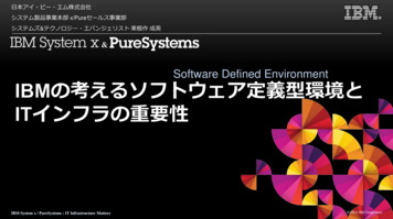
IntroductionAbout Cisco DNA CenterCisco DNA Center is the foundational controller and analytics platform at the heart of Cisco’s Intent-Based Network (IBN) forlarge and midsize organizations. Intent-based networking embodies the difference between a network that needscontinuous attention and one that simply understands what the organization needs and makes it happen. It is the differencebetween doing thousands of tasks manually and having an automated system that helps focus on business goals. Cisco DNACenter provides a centralized management dashboard for complete control of this new network. With this platform, IT cansimplify network operations, proactively manage the network, provide consistent wired and wireless policy, and correlateinsights with contextual cognitive analytics.Cisco DNA Center is a dedicated hardware appliance powered through a software collection of applications, processes,services, packages, and tools, and it is the centerpiece for Cisco Digital Network Architecture (Cisco DNA ). This softwareprovides full automation capabilities for provisioning and change management, reducing operations by minimizing the touchtime required to maintain the network. It also provides visibility and network assurance through intelligent analytics thatpull telemetry data from everywhere in the network. This reduces troubleshooting time and addresses network issuesthrough a single pane of management.This interconnection of automation and assurance forms a continuous validation-and-verification loop, driving businessintent and enabling faster innovation, lower cost and complexity, and enhanced security and compliance.About Cisco Digital Network ArchitectureCisco Digital Network Architecture (Cisco DNA ) provides a roadmap for digitization and a path to realization of theimmediate benefits of network automation, assurance, and security. Cisco DNA is an open, extensible, software-drivenarchitecture that accelerates and simplifies enterprise network operations while enabling business requirements to becaptured and translated into network policy. The result is constant alignment of the network to the business intent.Cisco DNA begins with the foundation of a digital-ready infrastructure that includes routers, switches, access-points, andwireless LAN controllers (WLC). The Identity Services Engine (ISE) is the key policy manager for the Cisco DNA solution. Thecenterpiece of Cisco DNA is the Cisco DNA Center controller which empowers simplified workflows using the Design,Provision, Policy, and Assurance applications.Figure 1Cisco DNA Center Dashboard6
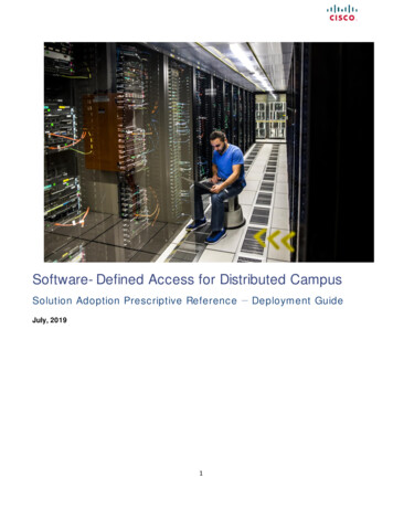
About Software-Defined AccessCisco Software-Defined Access (SD-Access) is the Cisco DNA evolution from traditional campus LAN designs to networks thatdirectly implement the intent of an organization. It is the intent-based networking solution for the Enterprise built on theprinciples of Cisco DNA. The SD-Access solution is enabled by an application package that runs as part of the Cisco DNACenter software and provides automated end-to-end segmentation to separate user, device, and application traffic. Theseuser access policies are automated so that organizations can ensure that the right policies are established for any user ordevice with any application anywhere in the network.SD-Access uses logic blocks called fabrics which leverage virtual network overlays that are driven through programmabilityand automation to create mobility, segmentation, and visibility. Network virtualization becomes easy to deploy throughsoftware-defined segmentation and policy for wired and wireless campus networks. Single physical networks are abstractedand can host one or more logical networks which are orchestrated through software. Error-prone manual operations inthese dynamic environments are circumvented altogether, providing consistent policy for users as they move around thewired and wireless network.About This GuideThis guide provides technical guidance for designing, deploying, and operating Software-Defined Access for DistributedCampus. It focuses on Cisco DNA Center to deploy the solution after the initial bootstrap of the network and supportinginfrastructure is complete.Figure 2This guide contains four major sections:Step 1:The DEFINE section defines the problem being solved with the SD-Access for Distributed Campus solutionand provides information on planning for the deployment and other considerations.Step 2:The DESIGN section shows a typical deployment topology and discusses Identity Services Engine and sharedservices considerations.Step 3:The DEPLOY section provides information and steps for the various workflows to deploy the solution alongwith recommended practices.Step 4:The OPERATE section demonstrates the manual configurations necessary for shared services, Internetaccess, and BGP between redundant device types.7
What is Covered in This Guide?This guide provides guidance to SD-Access customers deploying a unified and automated policy across multiple physicallocations in a metro-area network. The process, procedures, and steps listed in this guide are working configurationsverified with the Cisco DNA Center, ISE, IOS, IOS-XE, and AireOS code versions listed in Appendix A.What is Not Covered in This Guide?Although this deployment guide is about Cisco DNA Center and SD-Access, it does not cover the initial bootstrap andinstallation of the Appliance or of the ISE distributed deployment. Shared services installation and deployment, such asDHCP and DNS, along with the network connectivity configuration between various infrastructure components, routers, andswitches, are not specifically covered. SWIM (Software Image Management), LAN automation, multicast, Layer-2 handoff,fabric-in-a-box, and Cisco Catalyst 9800 embedded wireless on Catalyst series switches are also not covered.For more information on these items, please see additional references in Appendix B.Nomenclature ConventionsKnown routes, destinations, and prefixes are locations both inside the fabric and in the shared services Domains (DHCP, DNS,WLC, and ISE) that are registered with and known to the fabric control plane nodes.Unknown routes, destinations, and prefixes are locations on the Global Internet that are not known or registered with thefabric control plane nodes.LISP encapsulation or LISP data plane encapsulation in the context of SD-Access refers to the VXLAN-GPO encapsulation. Forbrevity, this may be referred to as VXLAN encapsulation. However, this is not meant to indicate or infer that theencapsulation method is the same VXLAN in RFC 7348 or associated with VXLAN MP-BGP EVPN.8
DefineThis section provides a high-level overview of the Software-Defined Access solution and components with a focus onelements related to distributed campus.Fabric Architectural ComponentsThe SD-Access 1.2 solution supports provisioning of the following fabric constructs:Fabric edge node: Equivalent of an access layer switch in a traditional campus LAN design. Endpoints, IP phones, andaccess points are directly connected to edge nodes.Fabric control plane node: Based on the LISP Map-Server (MS) and Map-Resolver (MR) functionality. The control planenode’s host tracking database tracks all endpoints in a fabric site and associates the endpoints to fabric nodes in what isknown as an EID-to-RLOC binding in LISP.Fabric border node: Serves as the gateway between the SD-Access fabric site and networks external to the fabric. Theborder node is the device physically connected to a transit or to a next-hop device connected to the outside world.Fabric site: An independent fabric that includes a control plane node and edge node and usually includes an ISE PolicyService Node (PSN) and fabric-mode WLC. A fabric border node is required to allow traffic to egress and ingress the fabricsite.Virtual Network (VN): Ostensibly a VRF definition. VNs are created in the Policy application and provisioned to the fabricnodes as a VRF instance. VN and VRF are used interchangeably in this document.Scalable Group Tag (SGT): A Cisco TrustSec component that operates as a form of metadata to provide logicalsegmentation based on group membership.Transit: Connects a fabric site to an external network (IP-Based transit) or to one or more fabric sites (SD-Access transit).IP-Based transit networks connect the fabric to external networks using VRF-lite. SD-Access transits carry SGT and VNinformation inherently carrying policy and segmentation between fabric sites and do not require or use VRF-lite.Fabric domain: Encompasses one or more fabric sites and any corresponding transit(s) associated with those sites.Transit control plane node: The transit control plane node’s database tracks all aggregate routes for the fabric domainand associates these routes to fabric sites. Its functionality is based on LISP Map-Server (MS) and Map-Resolver (MR).Fabric in a Box: Combines the fabric border node, fabric control plane node, and fabric edge node functionality on thesame switch or switch stack.Host Pool: The binding of a reserved IP address pool to a Virtual Network which associates a segment to a VRF.9
About Cisco Software-Defined Access for Distributed CampusCisco Software-Defined Access (SD-Access) for Distributed Campus is a metro-area solution that connects multiple,independent fabric sites together while maintaining the security policy constructs (VRFs and SGTs) across these sites. Whilemulti-site environments and deployments have been supported with SD-Access for some time, there has not been anautomated and simplistic way to maintain policy between sites. At each site’s fabric border node, fabric packets were deencapsulated into native IP. Combined with SXP, policy could be carried between sites using native encapsulation.However, this policy configuration was manual, mandated use of SXP to extend policy between sites, and involved complexmappings of IP to SGT bindings within the Identity Services Engine.With SD-Access for Distributed Campus, SXP is not required, the configurations are automated, and the complex mappingsare simplified. This solution enables inter-site communication using consistent, end-to-end automation and policy acrossthe metro network.Software-Defined Access for Distributed Campus uses control plane signaling from the LISP protocol and keeps packets inthe fabric VXLAN encapsulation between fabric sites. This maintains the macro- and micro-segmentation policy constructsof VRFs and SGT, respectively, between fabric sites. The original Ethernet header of the packet is preserved to enable theLayer-2 overlay service of SD-Access Wireless. The result is a network that is address-agnostic because policy is maintainedthrough group membership.10
DesignThis section introduces the SD-Access transit and transit control plane nodes along with key considerations, shows thedeployment topology, and discusses the Identity Services Engine and shared services.SD-Access TransitThe core components enabling the Distributed Campus solution are the SD-Access transit and the transit control planenodes. Both are new architectural constructs introduced with this solution. The SD-Access transit is simply the physicalmetro-area connection between fabric sites in the same city, metropolitan area, or between buildings in a large enterprisecampus.The key consideration for the Distributed Campus design using SD-Access transit is tha
About Software-Defined Access Cisco Software-Defined Access (SD-Access) is the Cisco DNA evolution from traditional campus LAN designs to networks that directly implement the intent of an organization. It is the intent-based networking solution for the Enterprise built on the principles of Cisco DNA.