Transcription
mechanical power take-offsGO WITH WHO YOU KNOWWith our vast network of locations around theworld, Twin Disc offers you unprecedented globalsales and service support. We can put engineeringand service expertise on location virtuallyanywhere. We’ll work with you on your particularapplication and product to ensure optimum results.We’re more than just a name you know,Twin Disc is a name you can trust.IMPORTANT NOTICE: Twin Disc, Incorporated reminds users of these products that their safe operation depends on use in compliance with engineering information provided in this catalog. Users are also reminded that safeoperation depends on proper installation, operation and routine maintenance and inspection under prevailing conditions. It is the responsibility of users (and not Twin Disc, Incorporated) to provide and install guards or safetydevices which may be required by recognized safety standards or by the Occupational Safety and Health Act of 1970 and its subsequent provisions.BULLETIN308S1/15 PRINTED IN U.S.A.TWIN DISC, INCORPORATED RACINE, WISCONSIN 53403, U.S.A. 262-638-4000/262-638-4481 (FAX) WWW.TWINDISC.COMU.S.A. AUSTRALIA BELGIUM CANADA CHINA INDIA JAPAN ITALY SINGAPORE SWITZERLANDWE PUT HORSEPOWER TO WORK SELECTIONGUIDE
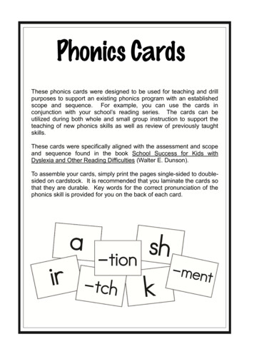
R TAKE-OFFS114.0 [4.49]An extra margin of strengthActual design torque capacity of the clutches used in Twin Discpower take-offs is in excess of the horsepower rating listed. This25.4permits Twin Discpower take-offs in proper adjustment to withstandtemporary torque overloads. Rated torque can be transmitted whilemoderately slipping during short periods without permanent damage.Ventilated Center Platesand Drive RingTapered RollerMain BearingsOptionalPilotBearingsHigher Side-Load177.8Carrying Capacity198.3Tapered RollerMain Bearingsÿ355.6 [14.00](8) 5/8 HEX. HD. BOLTSEQUALLY SPACEDINCH146.0KWY. LENGTH125.7 [4.95]323.8 [12.75]C(X) TYPE POWER TAKE-OFF Horsepower and torque capacities listed can be increased by theuse of sintered-iron clutch plates, which are available as optionalequipment in the 8" through 21" sizes. All bearings, shafts and other parts are designed with liberal safetyfactors to maximize life under normal operating conditions.*Limited-Attendance Power Take-Offs Modified SP & C Models Special grease on main bearings Sealed pilot bearings Lubrication interval can be extendedto 6 months Positive clearance mechanism toreduce collar wear SAE #0 through SAE #6 InputHousing 6” through 14” flywheel connectionRubber Block Drive Power Take-Offs RBD Models Direct drive / Clutchless Absorbs torsional activity Single row 11” rubber blocks Double row 14” rubber blocks SAE #0 through SAE #2 Input HousingInline Power Take-Offs SP, IB, & CA Models Bearings designed for in-lineonly duty Sealed pilot bearings Lubrication interval can beextended to 6 months SAE #0 & SAE #1 Input Housing 180 sheave housing rotatableby 90 incrementsPump Mount Power Take-Offs BDP & BDSP Models Single SAE pad on output of PTO SAE “A” through SAE “D”pads available SAE #1 through SAE #4 Input Housing 11.5” flywheel connection Optional keyed stub shaft input forremote mount applications349.2 [13.75]190.47ÿ 0.03355.5ÿ25.4 [1.00]22.2 x 22.2 x 146.0 KEY121.8 Standard sealed pilot ball or roller bearings eliminate the lubricationrequirement and shaft rifle-drilling normally encountered withstandard pilot bearings. Also available as options: ball bearingthrow-out collars and finger springs.Spring Loaded Power Take-Offs SL & TC Models Self-adjusting spring-loaded clutch Ideal for high frequency engagements Single- and double-friction plates 11”, 13”, 14” flywheel connection SAE #1 through SAE #4 Input HousingForged Steel LeversCentrifugal Assisted Release Suitable for Duty Class II industrial applications with internalcombustion engines up to 1667 horsepower and with standardSAE flywheel housing dimensions from No. 6 through No. 00. Contain clutches ranging in size from one plate 6 1 2" to oneplate 14"; in two-plate size from 11" to 18"; and three-platesize from 11" to 21".Straddle Bearing Power Take-Offs SP & PO Models High side-load applications No pilot bearing 14” & 18” flywheel connection SAE #0 & SAE #1 Input Housing 180 sheave housing rotatable by90 incrementsSP TYPE POWER TAKE-OFFOptionalPilotBearingsSpecificationsFor original equipment manufacturers, Twin Disc can design other special powertake-offs to meet individual requirements when sufficient volume is indicated.Design variations can range from minor changes to entirely new concepts.Forged Steel LeversCentrifugal Assisted Release38.1 [1.50] HEX.Twin Disc offers power take-offs for all industrial engines. The IBF76.2line is designed especially for today’s high inertia applications and(3.0)presently is offered in two- and three-clutch plate construction. Thismultiple-plate, ventilated design assures ample cooling area to withstand heat, and with solid friction plates, these PTOs can effectively58.9263.7handle the stress of higher engine speeds. The IBF units feature oillubricated tapered roller bearings that extend lubrication intervals.Special power take-offs are available from Twin Disc. These include the innovativestraddle bearing concept and a limited-attendance PTO that contains a positive throwout collar clearance mechanism and extended lubrication intervals.IB TYPE POWER TAKE-OFF68.61 [2.701]593.9 [23.38]Power take-offs (PTOs) are used as a standard method for transmittingÿ11.9 THRUINCH7/16-14 UNC-2B THD. THRUthe power of engines in a great2 HOLES,varietyindustrial applications such12 HOLES180?ofAPARTas air compressors, agricultural machinery, crushers, road EQUALLYbuildingSPACEDmachinery, cranes, shovels, pump drives and oil field service. A power19.05 SQ.184.15and beartake-off consists of a complete clutch assemblywithx shaftSQ.installation.x 7.25) KEYings mounted in a cast-iron housing for easy(0.75engineSPECIAL POWER TAKE-OFFS88.888ÿ 0.013TWIN DISC SETS THE STANDARD INOptional PilotBearingsBall or TaperedRoller Main BearingsNote: All dimensions given in inches unless noted.*To avoid overloading the shaft and bearings, use the allowable side-pull load data inthis bulletin, and calculate the side load. The resultant value should be less than the12.7 MIN.corresponding maximum value listed for each power take-off. In questionable cases,consult the Twin Disc Application Department, Twin Disc, Incorporated, Racine, Wisconsin. SUPPORT PLATESingle FrictionPlate only2
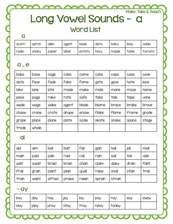
HOW TO CHOOSE THE APPROPRIATE PTOPTO SIZING EXAMPLE – Select the proper Twin Disc PTO for this applicationSeveral factors must be considered in the selection process in addition to duty service, such as:A disconnect PTO is required to drive a rotary screw compressor which is a Duty Class III application. The prime mover is a diesel enginerated for 200 hp @ 2,000 rpm. The engine has a SAE #2 flywheel housing and SAE 11.5" flywheel with a 72 mm pilot bearing bore. Thesheave pitch diameter mounted to the PTO shaft will be 13" and “V” belts are used for power transmission. The centerline of the loadimposed “X” dimension will be 4". Assume 5% parasitic losses from the engine for this specific application.SPEED LIMITS SIDE-LOAD LIMITS CLUTCH TORQUE LIMITSThe selections are usual dry clutch disconnect type applications where engagements are infrequent and are at low (idle)input speed. Once engaged operation continues for one hour or more, engaging the clutch at higher input speed willreduce component life. Refer to the following duty classifications and examples.1. D etermine the NET horsepower to the clutch (assume 5% parasitic losses.)200 hp gross x 0.95 190 hp NET2. Calculate the imposed side-load utilizing the following formula:Application Data*:SAE Housing SizeSAE Flywheel SizeNumber of EngagementsSheave Pitch DiameterPilot Bearing DiameterInput Power to ClutchInput Torque to ClutchMaximum Output Shaft RPMLoad Center-Line “X” Dimension (side-load applications)*refer to attached PTO data sheet located in back coverPTO Selection ProcedureThe SP311P has a Class III rating of 247 hp and max speed rating of 3,000 rpm with nodular iron drive rings. The application requires 190 hpinto the clutch @ 2,000 rpm, which are within the limits of the SP311P.1. Calculate NET Input Power or Torque to PTO2. Calculate imposed side-load using the following formula (side-load only):L 126,000 x HP x F x LFN x DMODEL NUMBERDESIGNATIONSP 3 11 P 3 XXBOM NumberLF 2.1 for reciprocating compressors and other Severe Shock Drives and 1.8 for Large Inertia Type Drives(crushers, chippers, planers, etc.)3. Use the PTO rating table on page 6 and the side-load tables on pages 7-8 with the following information:maximum PTO output shaft speedcalculated side-load (side-load applications)Find proper duty class along top row and SAE housing & flywheel size along left-hand column of the rating table onpage 6. A PTO that has a power or torque rating greater than the calculated application power or torque rating issuitable for the application. The PTO output shaft speed should be at or under the listed ratings for the drive rings.Use PTO output shaft speed and calculated side-load and refer to tables on pages 7-8 to verify that the side-load isat or under the load at the given speed.3T he side-load required for the application is 2,302 lbs at an “X” dimension of 4". The side-load capacity of the SP311P at an “X” dimension of4" for any rpm is 2,720 lbs. The application side-load of 2,302 lbs @ 4" is within the capacity of the SP311P.THE SP311P IS ACCEPTABLE FOR THIS APPLICATION AND IS AVAILABLE WITH A 72MM PILOT BEARING.Actual Applied Load (lbs)Shaft Speed (rpm)Sheave Pitch Diameter (in)Load Factor1.0 for Chain / Gear Drive1.5 for Timing Belts2.5 for All V Belts3.5 for Flat BeltsNET input power or torque to clutchSAE flywheel sizeSAE housing sizeF Load Factor1.0 for Chain/Gear Drive1.5 for Timing Belts2.5 for All V Belts3.5 for Flat Belts3. Use the following data and compare to the PTO rating and allowable side-load tables:– 190 hp NET to clutch– 2,302 lbs of side-load– SAE 11.5" flywheel– 2,000 rpm PTO shaft speed– SAE #2 housingDetermine duty classification (page 5)L N D F –L 126,000 x HP x F x LFN x DL Actual Applied Load (lbs)N Shaft Speed (rpm)D Sheave Pitch Diameter (in)LF 2.1 for reciprocating compressors andother severe shock drives and 1.8 for largeinertia type drives (crushers, chippers, planers.)L 126,000 x 190 hp x 2.5 2,302 lbs2,000 rpm x 13"SAE Housing – SAE 0, 1, 2, 3, etc.Output ConfigurationP – StandardSP – SpecialSB – Straddle BearingHP – Heavy DutyOP – Oil LubricatedIL – InlineClutch Size – Diameter in inchesNumber of Clutch Plates – 1, 2 or 3Type of ClutchC – Positive overcenter clutch suitable for power transmission applicationsCA – Positive overcenter for inline irrigation applicationsIBF – Inverted lever action clutchSP – Counter balanced toggle action overcenter clutch4
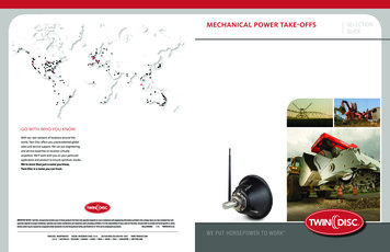
SELECTION GUIDE TO DUTY CLASSIFICATIONCLASS I (Disconnect)1. Pumps – centrifugal2. Hydraulic pumps (without pre-charge)3. Feeders – disc type4. Agitators – pure liquids5. Irrigation pumpsCLASS II (Light Duty)1. Cookers – cereal2. Elevators – bucket, uniformly loaded all types3. Kettles – brew4. Line shafts – light duty5. Machines, general – all types with uniform loads, non-reversing6. Bow thrusters7. Generators (non-welding)Duty Class I: The clutch is used for disconnecting the power from the load. When engaging,so little work is done that the clutch shows no temperature increase at the pressure plateouter surface. Use maximum input torque from the Class I Table, disregard horsepower.The mechanism is operated one or more hours before disconnecting.Examples: Engagement of clutches with the driven equipment having WR2 less than thatof the clutch and whose torque demand curve is similar to that of a centrifugal pump.Duty Class II: The clutch is used primarily for disconnect, but does more work during engagement than in Duty Class I. The clutch will engage within two seconds, never heat the pressureplate more than 50ºF (28ºC) above ambient, and once engaged is operated for one or morehours before disconnecting. The maximum horsepower which the clutch can absorb is givenin Class II Table.Examples: Power shovel master clutches, generators, line shafts and similar light-duty drives.CLASS III (Normal Duty)1. Agitators – solid or semi-solids2. Batchers – textile3. Blowers and fans – centrifugal and lobe4. Bottling machines5. Compressors – all centrifugal, screw6. Elevators – bucket, non-uniformly loaded or fed7. Feeders – apron, belt, screw or vane8. Filling machines – can-type9. Mixers – continuous10. Pumps – two or more cylinders11. Conveyors – uniformly loaded12. Dredge pumps (allow for shock loading)13. Locomotive railroad shuttlesDuty Class III: The clutch will engage within three seconds, never heat the pressureplate more than 100ºF (56ºC) above ambient, and once engaged is operated for one or morehours before disconnecting. The maximum horsepower which the clutch can absorb is givenin Class III Table.CLASS IV (Heavy Duty)1. Cranes and hoists – working clutch2. Crushers – ore and stone3. Chippers – wood tub grinders*4. Drums – barking*5. Compressors – lobe rotary plus 3 or more cylinder reciprocating type6. Haulers – car puller and barge-type7. Machines – impact load types*8. Mills – ball-type9. Paper mill machinery – except calendars and driers10. Presses – brick and clay11. Mud pumps12. Road planersDuty Class IV: The clutch will engage within four seconds, never heat the pressure plate morethan 150ºF (83ºC) above ambient, and once engaged is operated for one or more hours beforedisconnecting. The maximum horsepower which the clutch can absorb is given inClass IV Table.CLASS V (Extreme Heavy Duty)DUTY CLASS V REQUIRES FACTORY REVIEW1. Compressors – one and two cylinder reciprocating2. Calenders and driers
sheave pitch diameter mounted to the PTO shaft will be 13" and “V” belts are used for power transmission. The centerline of the load imposed “X” dimension will be 4". Assume 5% parasitic losses from the engine for this specific application. 1. Determine the NET horsepower to the clutch (assume 5% parasitic losses.) 200 hp gross x 0.95 190 hp NET 2. Calculate the imposed side-load .