Transcription
Powder Technology 313 (2017) 18–26Contents lists available at ScienceDirectPowder Technologyjournal homepage: www.elsevier.com/locate/powtecThe rupture force of liquid bridges in two and three particle systemsDiana Lievano, Sachin Velankar, Joseph J. McCarthy*Department of Chemical and Petroleum Engineering, University of Pittsburgh, Pittsburgh, PA 15261, USAA R T I C L EI N F OArticle history:Received 2 June 2016Received in revised form 22 December 2016Accepted 22 February 2017Available online 24 February 2017Keywords:Pendular saturationMeniscusCapillarityViscosityCapillary saturationStatic ruptureA B S T R A C TThe measurement of the rupture force for an axially strained liquid bridge has been the subject of researchfor the last three decades and is fundamental to the understanding of the behavior of multiphase systems ingranular materials. The study herein presents experimental work measuring the rupture force of pendularand capillary bridges in a three-particle configuration providing an axial and a shear strain. Results andsubsequent analysis indicates that the rupture force and maximum rupture distance are the effect of surfacecharacteristics, straining mechanism and effective liquid volume. For systems of more than two particles,we note that the effective packing fraction of the particles has a significant impact on the force required torupture such a bridge. 2017 Elsevier B.V. All rights reserved.1. IntroductionInvestigating the phenomena involved in solid–liquid interactions is important due to the ubiquitous presence of compoundsolid–liquid systems among a variety of industries (i.e. pharmaceutical, chemical, cosmetic, and agricultural) and with diverse chemicaland physical applications, such as agglomeration, and crystal growth.In these systems strong adhesion can result from the liquid meniscus that forms around the point of contact between solid surfaces [1].This force is called the capillary force. In a two-particle system, thesemenisci bind solid surfaces by creating a bond between two finitecontact points. The phenomenon of capillary adhesion is of greatimportance for granular materials and powders in the macroscale [2].While the formation of agglomerates is commonplace in the industrial processing of solid mixtures, axial straining of a liquid bridge, inparticular, can be evidenced in the granulation process.Understanding and modeling multiphase systems is complex dueto the different forces acting on the solids depending on the volume of fluid present. Depending on the liquid volume-capillary,surface and viscous forces can appear and change the mechanicalproperties of the mixture, such as its tensile strength [3–5]. Theincreasingly intricate interactions between the solid and liquid components, as the saturation level increases, has limited most of the* Corresponding author.E-mail address: jjmcc@pitt.edu (J.J. 02.0530032-5910/ 2017 Elsevier B.V. All rights reserved.available experimental studies to the pendular regime, and analytical models are developed for stable pairwise, axisymmetric bridges.Furthermore, the study of the formation and rupture of binding liquid networks has the added problem of bridge stability, particularlywhen dealing with bridges linking spherical solids. To forgo thisproblem most studies are limited to working with small liquid volumes (relative to particle size) such that a stable meniscus can besustained between the solids [6,7]. A formal definition of what weconsider to be small liquid volumes will be discussed later.The attraction or repulsion forces between solids and the interstitial liquid are a result of a pressure differential across the interface.The pressure differential can be calculated using the Young–Laplace(YL) equation if the shape of the meniscus is known [2]. MegiasAlgacil & Gauckler [8,9] recently presented a study for the capillaryforces between spheres for liquid volumes forming both concave andconvex liquid bridges. The results analyze the nature of the cohesive forces and present values for contactangle and relative liquid volume, defined as Vrel V / 43 pR3 , for which a concave or convex meniscus can be expected. Urso et al. [10,11] present theoreticaltwo-dimensional studies for the rupture of liquid bridges including the transitional states between pendular and capillary saturationlevel. They introduce equations to calculate the area of the liquidbridge surface for different saturation states and meniscus geometries. Murase et al. [12,13] presented a first attempt at characterizingthe straining phenomena for a liquid bridges of different volumesheld between three spheres both experimentally and computationally. They focused largely on the differences between dynamic and
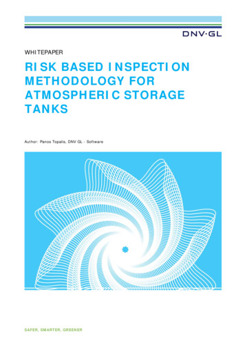
D. Lievano et al. / Powder Technology 313 (2017) 18–2619static pendular bridge forces and conclude that the maximum tensileforce of the liquid bridge is the same for the two and three spheresystem for a static rupture mechanism, but two times larger for thethree-particle configuration under dynamic rupture conditions.It is the objective of this study to perform experimental measures for the rupture force of menisci between two- and three-sphereinteractions. We will follow the taxonomy described by Urso et al.[10,11], where bridges between two particles are termed pendular, systems where the particle interstices are fully saturated arecalled capillary, and intermediate saturations where there are varying degrees of interstitial voids are considered to represent funicularsaturation. This work will measure both pendular and capillary rupture forces with a focus on the impact of bridge volume and particlesymmetry effects.1.1. The rupture of a pendular liquid bridgeThe rupture force for pendular liquid bridges has been studiedfor decades [2,4,5,14-18]. Particle–plane and particle–particle interactions have been modeled for spherical particles and small liquidvolumes. In general, the solution to the rupture energy of a liquidbridge can be found by considering it as a two-part problem. First,the stability problem and second, the net attraction/repulsion forcesinduced by the formation of liquid bridges [4].When considering a packed bed, the theory for different saturation levels identifies the limit of the pendular regime at 13%moisture content, while the funicular regime is identified as corresponding to a moisture content above 13% and up to 25% [19]. It isknown additionally, that for small enough volumes, where the effectof gravity can be neglected, the mean curvature of the bridge surfacebetween two spheres may be approximated as constant and the contact point is fixed [20]. The maximum volume of fluid, for which theeffects of gravity can be considered negligible, is estimated using thefollowing equation: j s,gq(1)where ql is the density difference between the solid and the liquidphases, and j is known as the capillary constant, or capillary length.In order to model such interactions it is necessary to solve theYoung–Laplace (YL) equation for capillary forces in the presence ofa curved liquid-vapor interface. The pressure differential across theliquid-gas interface, is defined by the shape of the meniscus. It iscommonplace to assume the shape of the meniscus is describedby a solid of revolution [21]. While numerical solutions for the YLequation for a wide variety of revolution surfaces are known, moreoften than not, an equation based on a toroidal shape is implemented [7,22,23]. Based on this approach, in order to perform anaxially oriented force balance, first a system in equilibrium is defined(Fig. 1). Then, making use of the surfaces of revolution to calculate thepressure differential across the liquid–gas interface according to YL,one employs the theories of capillarity and lubrication to calculatethe total cohesive force [24,25].The work discussed herein follows the procedure described byPitois et al. for the rupture energy of a pendular liquid bridge [24].The simplified dimensionless expression derived for the capillaryforce contribution takes the form FcapFcap 2p cos 0fv , sRwhere D is the distance between the two solid surfaces, s is the fluidsurface tension, and 0 is the solid-liquid wetting angle. The star symbol ( ) denotes the dimensionless form of an expression. The lengthscale to write dimensionless parameters is the radius of the sphere R,such that V V/R3 , D D/R. Similarly, we use as the force scalesR (see Eq. (2)).1.2. Viscous forcesAn expression for the viscous force contributions to granular systems was developed by Ennis et al. based on a derivation of theReynolds equation to describe thin film behavior [7]. The functionrevealed how the contribution of lubrication forces to the total rupture force becomes increasingly important for high viscosity fluids.While the objective of the current work is focused on low viscosityfluids only, we have implemented the viscous contribution as part ofthe computational model for completion. The viscous contribution,in its dimensionless form, can be written as: Fvisc 3 Cap f22 D v(4)where, Ca is the capillary number defined as Ca ls /a, and l is theviscosity of the fluid. It follows that the total (dynamic) force is thesum of the capillary and viscous terms. A relationship between theliquid bridge volume, the liquid–solid contact angle and the quasistatic rupture distance, was presented by Lian et al. [22] for liquidvolumes where the effect of gravity can be neglected. Their rupturedistance can be written as: 0D rupt 1 V 1/3 .2(5)The total liquid bridge force contribution can then be expressed as: Ftot 2p cos 0fv 3 Ca 2p f2 D v(6)(2)with, 1 (2V ) 2fv 1 1 ,(pD 2 )Fig. 1. Sketch of a liquid bridge formed between two spheres. P1 and P2 are planes ofsymmetry.(3)Key contributors to viscous forces, such as wetting angles, andstability on curved surfaces have become areas of independent studies [26–28]. Results indicated that minimal shifts in the shape ofthe meniscus had a significant impact on the evolution and rupture of the bridge. The present work will be concerned with steadystate, non-thermodynamic equilibrium, and will assume the bridge
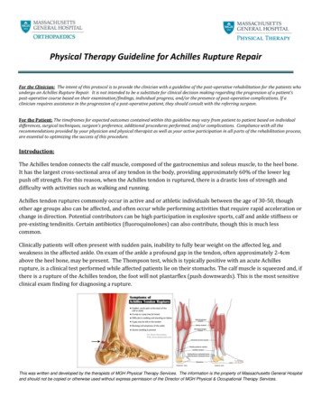
20D. Lievano et al. / Powder Technology 313 (2017) 18–26maintains a constant mean-curvature. Adams et al. [29] present astudy on mapping the influence of gravitational forces for the liquid binding of solid spheres. The Bond number (Bo) – defined asBo Dqgd2 /s where d is the characteristic length – is used to quantify the gravitational distortion for a free liquid droplet. It serves as acharacterization parameter when a scaling factor – which is a function of the liquid bridge volume (V) – is introduced. The modifiedBond number is defined as V Bo and was used in Ref.[29] to predictthe influence of gravitational forces. In this work, Adams et al. identified systems that have V Bo 0.01 as being essentially gravityfree, while systems in the range 0.01 V Bo 0.015 are deemedtransitional and those with V Bo 0.015 are the considered to begravity controlled systems (that is, they are systems in which thegravity component plays a significant role in the meniscus evolutionand subsequent bridge rupture). For axisymmetric pendular ringsbetween a sphere with radius R and a flat surface, the Bond number is expressed as Bo DqgR2 /s where the characteristic lengthis the particle radius. For while for a liquid bridge between identical spheres, on the other hand, the Bond number can be expressed interms of the liquid volume (V), as:Bo DqgV /Rs .(7)When the largest dimension of a sessile drop exceeds j the gravitational effects become significant, and the straining of a liquid bridge(between two spheres) produces a decrease in the liquid filling angle(b) of the top sphere as separation increases (see Fig. 1) until eventually the bridge becomes unstable. For these cases, Adams et al.suggest a modified rupture criterion of the formD rupt (1 0.48V Bo)V 1/3 .(8)Fig. 2. Micromechanical force microscope: Brookfield texture analyzer casing,stainless-steel retractible cantilever, optical displacement sensor.2. Materials & methodsRupture tests were performed using acrylic beads of 2 mm indiameter. Ethylene-glycol (EG) was selected as the fluid to minimizeevaporation at ambient conditions (refer to Table 1 for relevant fluidproperties). Different fluid volumes were tested in order to describethe relationship between liquid volume and rupture behavior in thependular and capillary regimes.2.1. Measurement of micromechanical forces in an axially strainedliquid bridgeTo measure the rupture forces of liquid binding networks, amicro-mechanical force microscope was constructed, which consists of a (Philtec) fiberoptic sensor, a stainless-steel cantilever anda moving stage. Data is collected and interpreted using two essential components: (1) a multi-purpose texture analyzer (BrookfieldEngineering), and (2) a DMS optical displacement sensor. The twodevices are coupled via a stainless-steel cantilever (thickness 0.007 inches), see Fig. 2. The fiberoptic sensor can be programmed toTable 1Properties for ethylene glycol at 20 C.PropertyValueUnitsMolar massDensityViscositySurface tension62.071.110.0150.048g/molg/cm3Pa sN/mtranslate the reflectivity measurement to a distance and is calibratedin-situ. The reflectivity itself is a function of the cantilever propertiesas well as the finished surface.The texture analyzer (TA) holds the stage for the static bottomparticle(s), as well as the retractable shaft, which is fitted with acustom stainless-steel cantilever. A retracting particle – identical tothe stationary one(s) – is fixed to the underside of the distal end ofthe cantilever. This sphere cantilever unit is the sole mobile elementin this setup, which simultaneously imparts axial strain on liquidbridges and measures the force between the particles within the system. Directly above and parallel to the cantilever is an arm whichholds the optical displacement sensor. As the shaft is raised, liquidforces operating on the retracting sphere bend the cantilever from itsresting position. As the distance between the cantilever and the optical sensor changes, the reflectivity of the cantilever beam is alteredand this change is calibrated to yield a strain (length). Based on themeasured bending modulus of the cantilever, this strain is convertedto a force. The choice of cantilever thickness is determined via trialand-error in which different thicknesses impact the accuracy of forcemeasurement (due primarily to a changing signal-to-noise ratio).In practice, we base our selection of cantilever on a calibration ofthe strain to force conversion over the entire range of interest. Theparticle, cantilever and sensor configuration is displayed in Fig. 2.The retraction velocity employed must ensure slow displacementof the cantilever such that the rupture is considered quasi-static. TheTA device allows setting the shaft displacement at 10 lm/s, a velocity slow enough to capture the static rupture as indicated in Fig. 4.
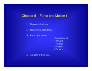
D. Lievano et al. / Powder Technology 313 (2017) 18–26The optical sensor software keeps a real-time record of the reflectivity as well as the distance between the sensor tip and the cantileversurface. Having a set, constant shaft-speed allows for the straightforward calculation of the distance displaced in time. A qualitativeanalysis of the primary experimental measurements is performed inorder to validate that the shaft operating velocity used in this workis slow enough to approximate quasi-static operation. The rupture ofa liquid bridge under dynamic conditions is beyond the scope of thecurrent work.Making use of Eqs. (1) and 5, inserting the corresponding values for gravity and EG properties (i.e. density, surface tension, seeTable 1), we calculate the rupture distance and relate it to the particle volume proposed by Lian et al. [22]. A gravity free liquid bridgecorresponds to effective volumes where V*1/3 j, following therationale presented in Eq. (1) [1]. Therefore, for the particles usedin this study the maximum volume allowable in order to correctlyneglect gravitational forces is 0.5 lL. This calculated volume highlights the importance of operating with small particles. Operatingwith liquid volumes above 0.5 lL could give rise to non-negligiblegravitational forces [22].21Fig. 3. Image of a pendular liquid bridge between two spheres. The top sphere isattached to the cantilever and the bottom sphere is held static. Straining of the liquidbridge is a result of the upwards movement of the top sphere at constant speed.2.2. Experimental methodologyEach run is initiated in the same manner; a drop of volume V iscarefully dispensed with a syringe on top of the bottom sphere(s),which remain static. The cantilever sphere is then slowly broughtinto contact first with the liquid drop(s) then with the opposing particle surface(s). After contact with the drop(s), the liquid is displacedto the surface surrounding the contact spot(s). The instant the topbead starts retracting by action of the shaft, the fluid will make itsway into the newly available gap and produce the peak force readingin the force distance diagram. In the case of three-particle interactions, drops of EG – comprised of varying volumes – are applied tothe top surfaces of each static bead, such that when the cantileversphere is lowered, a liquid bridge conjoins all particles (either withone large capillary bridge or two (separate) pendular bridges). Asbefore, prior to the start of each trial, the top and bottom beads arepositioned in direct contact.The data is herein presented in dimensionless terms, unlessstated otherwise. Terms will be made dimensionless by using theparticle radius, and surface tension of the fluid, ethylene glycol (EG).measured and theoretical curves lends validity to the assumptionthat our experimental setup accurately approximates static operation. It is accepted from here on that measurements taken employingthis methodology and operational parameters correspond to quasistatic behavior of the liquid system and the term will be omitted forthe sake of brevity.In addition to this, for the widely studied plate and sphere system,the rupture distance obtained experimentally follows the relationpredicted by Lian et al. [22], Eq. (5). The selection of EG as the fluidhas the advantage of displaying contact angles close to zero, therefore assuming 0 0 for all systems the above expression reduces toD̃rupt V 1/3(9)which underestimates the rupture distance observed in Fig. 4 by 11%.3. Results and analysisIn the interest of verifying the accuracy of the measurementsrecorded by the micro-mechanical force microscope, initial testswere aimed at validating the experimental methodology. Accordingly, the rupture force for a single pendular liquid bridge wasmeasured for a sphere-plane configuration. Fig. 4 presents the tensile strength behavior between a glass plate and a sphere measuredexperimentally and compared to the corresponding theoretical function as a function of the separation between particles D. For allforce curves presented herein, the last point plotted represents themaximum separation achieved before rupture occurred.The theoretical curves shown in Fig. 4 were plotted following theanalysis presented by Pitois et al. which calculates the quasi-staticadhesive force for a constant liquid bridge volume with pinned contact points (refer to Eqs. (2) and 4; [25]). The fluid properties of EGwere used in the theoretical calculations. The total force data appearsto lie on the same curve as the capillary force equation (Fig. 3), whichsupports that capillary, not viscous, forces dominate in this system.Throughout the range of particle separation the measured data fallswithin two standard deviations (based on five independent trials)from the theoretical curve. The agreement observed between theFig. 4. Quasi-static force between an acrylic sphere and glass plane forming a pendular liquid bridge measured experimentally compared with the calculated theoretical values for Fcap(Eq. (2)), and Ftot(Eq. (6)) as described by Pitois et al. The fluid used isethylene glycol.
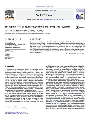
22D. Lievano et al. / Powder Technology 313 (2017) 18–26Table 2Properties for ethylene glycol at 20 C.Target V V BoV*1/3D rup (gravitational 30.790.901.01.30.630.750.830.890.983.1. Liquid bridges between two particlesCalculating the modified Bo number suggests that only dimensionless volumes above one (1) will exhibit gravity effects that affectthe draining mechanism. Here, our use of the term draining mechanism refers to the observed retraction and redistribution of fluid asthe liquid bridge is stretched (and ultimately ruptured). In the moresimple particle-wall or 2-particle systems the draining mechanism isthe same for all liquid volumes, being characterized by the formationof a (thinning) bridge neck at approximately h S/2 as stretchingoccurs. When rupture occurs, the neck region breaks and there aretwo resulting droplets of similar volumes that remain at the contactpoint of both the top and bottom particle. For more complex systemswith three particles and multiple liquid bridges the draining mechanism is dependent on the degree of symmetry of the initial condition,see Fig. 7. Table 2 presents values of liquid volume that are used inthe experimental trials described in this section. According to theV Bo values calculated, we expect the liquid volumes 0.5 V 0.75to be in the transitional regime, where there is a significant decreasein the rupture distance and change in the force by half of the bridgeweight. Similarly, for volumes where V 0.75, we anticipate beingin the gravity controlled regime. The expected rupture distances arealso presented in the table based on Eqs. (9) or 8 (according to theexpected gravitational regime).According to the modified rupture distance approximation proposed by Adams et al. the gravitational effects reduce the rupturedistance as much as 20% for the larger liquid volumes dispensed.In order to observe the sensitivity of the measurements, theresults for three characteristic runs are plotted for each (liquid volume) condition. The two-particle bridge rupture results presented inFig. 5 are further supported by other indicators reported in literature.Most notably, the maximum force is about half of the sphere-planerupture force [1], for the same liquid volume.The measured tensile force of the liquid bridge is in accordancewith theoretical values presented by Willett et al. [17] where themaximum capillary force is considered insensitive to the liquid volume for pendular bridges, without gravity effects. In addition tothis, Willet et al. reported rupture distances being overestimated byEq. (5), and suggested an alternate best-fit solution of the form: 0V 2/3D rupt 1 V 1/3 .210(10)Results presented in Fig. 5 also support this observation, as theexpected rupture distances are underestimated by Eqs. (9) and 8,whereas the modified expression presented by Willet et al. describesaccurately the results presented for two particles.3.2. Three particle system and capillary liquid bridgesWhen testing a three-particle set-up, two different configurationswere used: one simulating a high solid fraction — where particles arecloser together; and one simulating a low solid fraction — where thestationary particles are separated. A setup with a center-to-centerdistance between the two bottom spheres of d d/R 2.5 waschosen as the high solid fraction condition, to test a triple contactstarting point. The initial condition for the force measurement iswhen the drop is in contact with all three spheres. The results forthree different effective liquid volumes are presented in Fig. 6.Contrary to the experimental results presented in Murase et al.[12] the observed trend for the force of a single liquid bridge in contact with three spheres (Fig. 6) does not result in the same maximumFig. 5. A) Experimentally measured capillary force versus separation curves for an axially strained pendular liquid bridge formed between two identical acrylic spheres(R 1 mm). Three runs for each corresponding liquid volume (V 0.25, V 0.50) of ethylene glycol are presented. B) Picture liquid bridge of volume V 0.25. C)Picture liquid bridge of volume V 0.50.
D. Lievano et al. / Powder Technology 313 (2017) 18–2623Fig. 6. A) Measured liquid bridge force for a single axially strained bridge in contact with three identical acrylic spheres. Three runs are plotted for each of the liquid volumesused (V 0.25, V 1.0). The center-to-center distance for the bottom spheres is d 2.5. B) Picture liquid bridge V 0.25. C) Picture liquid bridge V 1.0.capillary force as it does for two spheres (Fig. 5). In fact, the maximum measured force is higher when the liquid bridge is stretchedover three particles, where we obtain a value comparable with themaximum force for a liquid bridge between a sphere and a plane. Thiscan be explained by the fact that the liquid volume distributes amongthe two bottom spheres creating a meniscus with a shape closer tothat formed between a sphere and a plane.The rupture distance, on the other hand, is reduced by about 20%for the gravity-free volume of V 0.25, and is roughly half theexpected length for the capillary saturation volume of V 1.0, indicating that rupture distance approximations are only applicable forpendular liquid bridges.We should note that, for capillary saturation volumes, imprecisedraining mechanisms were observed for some of the runs. Duringthese runs the liquid meniscus shifts forming a two-particle bridgebetween the cantilever sphere and only one of the static beads. In themost frequently seen draining mechanism, a single bridge forms as itdoes between two spheres, yet the neck of the meniscus forms closerto the top sphere allowing the majority of the volume to be balancedbetween the bottom two (see Fig. 7).The second configuration tested was that mimicking a low solidfraction particle bed, meaning there is a greater gap between adjacent spheres. Again, two drops are dispensed – one above each ofthe bottom spheres – which now lay at a measured center-to-centerdistance of d 3.2, Fig. 8B and C. The cantilever is lowered untilthe top sphere makes contact with the two bottom spheres withoutallowing the two drops to coalesce. For these cases the liquid volumereported corresponds to the liquid volume per bridge, meaning thetotal liquid volume of the system is twice as much.The maximum force for two liquid bridges held in a threeparticle configuration presents two noteworthy characteristics. First,the maximum force is larger than that of a single liquid bridge heldbetween two spheres. A way to understand this is to think of twosprings in parallel. Two identical springs in parallel exert a force thatis effectively twice the force of a single bridge, Fig. 9A; however,when these springs are inclined at an angle (h) the force is reducedby a factor of sinh, as in Fig. 9B. For the configuration used in ourexperimental trials the true angle between the particle centers isapproximately h 50 ; however, using this correction overestimatesthe degree to which the maximum bridge force increases, perhapsFig. 7. Comparison of the two primary draining behavior observed for a single bridge between three identical spheres. Left: Axially strained single bridge where the neck of themeniscus is located closer to the top sphere. Right: Asymmetrical draining and rupture of the meniscus.
24D. Lievano et al. / Powder Technology 313 (2017) 18–26Fig. 8. A) Measured capillary force between for two axially strained liquid bridges formed between three identical spheres. Two separate drops are initially placed on top of eachof the bottom spheres. Three runs are plotted for each of the liquid volumes used (V 0.25, V 0.50, and V 0.75). The center-to-center separation between the bottomparticles is d 3.2. B) Picture liquid bridge V 0.25. C) Picture liquid bridge V 0.50. D) Picture liquid bridge V 0.75.due to interactions between the wetted contact spots on the central particles. Second, the maximum force is seen to increase withincreased liquid volume, despite the presence of pendular bridges,ostensibly in contrast to the findings of Willett et al. [17] (and ourresults in Fig. 5). We believe that this can be explained as a consequence of two factors: as the liquid volume increases, the effectiveangle observed between the bridges decreases (thus the factor of sinhincreases); additionally, the increased liquid volume is large enoughto set our results into the transitional gravitational regime (whereliquid volume is expected to affect the maximum force observed).The rupture distance for this case is similar to that of the twoparticle configuration, and is approximated to a good degree byEq. (10) for V 0.25 and V 0.5. For V 0.75 the rupturedistance is better predicted by the modified rupture proposed byAdams et al., for liquid bridges in the transitional regime, indicatingthe latent effect of gravitational forces for this volume.Finally in Fig. 10, we compare the rupture force for a dispensedvolume of V 2.0 distributed among two or three particles. Interestingly, for these large liquid volumes we still don’t perceive asignificant reduction of the maximum capillary force due to gravitational effects. They do, however, exhibit a reduction in the rupturedistance that is more significant for the three-particle system thanit is for the two-particle configuration. In addition to this, the maximum force is comparable between the close-packed three-particleand the plate-sphere configuration. This can be explained by observing the meniscus shape for both systems, where a single drop incontact with three spheres creates a meniscus geometry that moreclosely resembles that formed between a sphere and plate. From aqualitative standpoint, our results are a
ing degrees of interstitial voids are considered to represent funicular saturation. This work will measure both pendular and capillary rup-ture forces with a focus on the impact of bridge volume and particle symmetry effects. 1.1. The rupture of a pendular liquid bridge The rupture force for pendular liquid bridges has been studied