Transcription
Network Virtualization in Multi-tenant DatacentersTeemu Koponen, Keith Amidon, Peter Balland, Martín Casado, Anupam Chanda, BryanFulton, Igor Ganichev, Jesse Gross, Natasha Gude, Paul Ingram, Ethan Jackson, AndrewLambeth, Romain Lenglet, Shih-Hao Li, Amar Padmanabhan, Justin Pettit, Ben Pfaff,and Rajiv Ramanathan, VMware; Scott Shenker, International Computer Science Instituteand the University of California, Berkeley; Alan Shieh, Jeremy Stribling, Pankaj Thakkar, DanWendlandt, Alexander Yip, and Ronghua Zhang, hnical-sessions/presentation/koponenThis paper is included in the Proceedings of the11th USENIX Symposium on Networked SystemsDesign and Implementation (NSDI ’14).April 2–4, 2014 Seattle, WA, USAISBN 978-1-931971-09-6Open access to the Proceedings of the11th USENIX Symposium onNetworked Systems Design andImplementation (NSDI ’14)is sponsored by USENIX
Network Virtualization in Multi-tenant DatacentersTeemu Koponen , Keith Amidon , Peter Balland , Martín Casado , Anupam Chanda ,Bryan Fulton , Igor Ganichev , Jesse Gross , Natasha Gude , Paul Ingram , Ethan Jackson ,Andrew Lambeth , Romain Lenglet , Shih-Hao Li , Amar Padmanabhan , Justin Pettit ,Ben Pfaff , Rajiv Ramanathan , Scott Shenker†, Alan Shieh , Jeremy Stribling ,Pankaj Thakkar , Dan Wendlandt , Alexander Yip , Ronghua Zhang †VMware, Inc.UC Berkeley and ICSIOperational Systems Track ABSTRACTAddress space: Virtualized workloads today operate inthe same address space as the physical network.1 That is,the VMs get an IP from the subnet of the first L3 routerto which they are attached. This creates a number ofproblems: Operators cannot move VMs to arbitrary locations. Operators cannot allow VMs to run their own IPAddress Management (IPAM) schemes. This is acommon requirement in datacenters. Operators cannot change the addressing type. Forexample, if the physical network is IPv4, theycannot run IPv6 to the VMs.Ideally, the networking layer would support similarproperties as the compute layer, in which arbitrarynetwork topologies and addressing architectures couldbe overlayed onto the same physical network. Whetherhosting applications, developer environments, or actualtenants, this desire is often referred to as shared multitenancy; throughout the rest of this paper we refer to thisas a multi-tenant datacenter (MTD).Unfortunately, constructing an MTD is difficult because while computation is virtualized, the network isnot. This may seem strange, because networking has longhad a number of virtualization primitives such as VLAN(virtualized L2 domain), VRFs (virtualized L3 FIB), NAT(virtualized IP address space), and MPLS (virtualizedpath). However, these are traditionally configured on abox-by-box basis, with no single unifying abstractionthat can be invoked in a more global manner. As aresult, making the network changes needed to supportserver virtualization requires operators to configure manyboxes individually, and update these configurations inresponse to changes or failures in the network. Theresult is excessive operator overhead and the constantrisk of misconfiguration and error, which has led topainstaking change log systems used as best practice inmost environments. It is our experience in numerouscustomer environments that while compute provisioningis generally on the order of minutes, network provisioningcan take months. Our experience is commonly echoed inanalyst reports [7, 29].Multi-tenant datacenters represent an extremely challenging networking environment. Tenants want the abilityto migrate unmodified workloads from their enterprisenetworks to service provider datacenters, retaining thesame networking configurations of their home network.The service providers must meet these needs withoutoperator intervention while preserving their own operational flexibility and efficiency. Traditional networkingapproaches have failed to meet these tenant and providerrequirements. Responding to this need, we present thedesign and implementation of a network virtualizationsolution for multi-tenant datacenters.1IntroductionManaging computational resources used to be a timeconsuming task requiring the acquisition and configuration of physical machines. However, with servervirtualization – that is, exposing the software abstractionof a server to users – provisioning can be done in thetime it takes to load bytes from disk. In the past fifteenyears server virtualization has become the dominantapproach for managing computational infrastructures,with the number of virtual servers exceeding the numberof physical servers globally [2, 18].However, the promise of seamless management throughserver virtualization is only partially realized in practice.In most practical environments, deploying a new application or development environment requires an associatedchange in the network. This is for two reasons:Topology: Different workloads require different networktopologies and services. Traditional enterprise workloadsusing service discovery protocols often require flat L2,large analytics workloads require L3, and web servicesoften require multiple tiers. Further, many applicationsdepend on different L4-L7 services. Today, it is difficultfor a single physical topology to support the configurationrequirements of all of the workloads of an organization,and as a result, the organization must build multiplephysical networks, each addressing a particular commontopology.1This is true even with VMware VDS and Cisco Nexus 1k.1USENIX Association11th USENIX Symposium on Networked Systems Design and Implementation 203
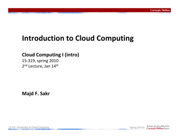
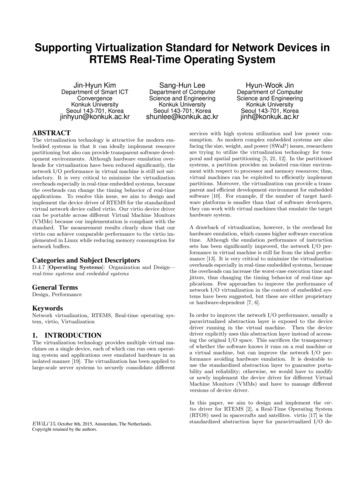
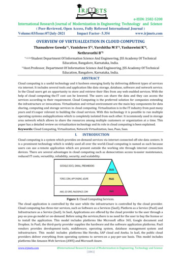
Academia (as discussed in Section 7) and industryhave responded by introducing the notion of networkvirtualization. While we are not aware of a formaldefinition, the general consensus appears to be that anetwork virtualization layer allows for the creation ofvirtual networks, each with independent service models,topologies, and addressing architectures, over the samephysical network. Further, the creation, configuration andmanagement of these virtual networks is done throughglobal abstractions rather than pieced together throughbox-by-box configuration.And while the idea of network virtualization is notnew, little has been written about how these systems areimplemented and deployed in practice, and their impacton operations.In this paper we present NVP, a network virtualizationplatform that has been deployed in dozens of productionenvironments over the last few years and has hosted tensof thousands of virtual networks and virtual machines.The target environment for NVP is enterprise datacenters,rather than mega-datacenters in which virtualization isoften done at a higher level, such as the application.2CPVMCPControlAbstractionL3L2VMNetwork HypervisorPhysical Forwarding InfrastructureFigure 1: A network hypervisor sits on top of the service providerinfrastructure and provides the tenant control planes with a controlabstraction and VMs with a packet abstraction.Control abstraction. This abstraction must allow tenants to define a set of logical network elements (or, as wewill call them, logical datapaths) that they can configure(through their control planes) as they would physicalnetwork elements. While conceptually each tenant hasits own control planes, the network hypervisor providesthe control plane implementations for the defined logicalnetwork elements.2 Each logical datapath is definedby a packet forwarding pipeline interface that, similarto modern forwarding ASICs, contains a sequence oflookup tables, each capable of matching over packetheaders and metadata established by earlier pipelinestages. At each stage, packet headers can be modified orthe packet can be dropped altogether. The pipeline resultsin a forwarding decision, which is saved to the packet’smetadata, and the packet is then sent out the appropriateport. Since our logical datapaths are implemented insoftware virtual switches, we have more flexibility thanASIC implementations; datapaths need not hardcode thetype or number of lookup tables and the lookup tables canmatch over arbitrary packet header fields.Packet abstraction. This abstraction must enable packets sent by endpoints in the MTD to be given the sameswitching, routing and filtering service they would havein the tenant’s home network. This can be accomplishedwithin the packet forwarding pipeline model describedabove. For instance, the control plane might want toprovide basic L2 forwarding semantics in the form ofa logical switch, which connects some set of tenantVMs (each of which has its own MAC address and isrepresented by a logical port on the switch). To achievethis, the control plane could populate a single logicalforwarding table with entries explicitly matching ondestination MAC addresses and sending the matchingpackets to ports connected to the corresponding VMs.Alternatively, the control plane could install a speciallearning flow that forwards packets to ports where trafficfrom the destination MAC address was last received(which will time out in the absence of new traffic)and simply flood unknown packets. Similarly, it couldbroadcast destination addresses with a flow entry thatsends packets to all logical ports (excluding the port onwhich the packet was received) on the logical switch.System DesignMTDs have a set of hosts connected by a physical network.Each host has multiple VMs supported by the host’shypervisor. Each host hypervisor has an internal softwarevirtual switch that accepts packets from these local VMsand forwards them either to another local VM or over thephysical network to another host hypervisor.Just as the hypervisor on a host provides the rightvirtualization abstractions to VMs, we build our architecture around a network hypervisor that provides theright network virtualization abstractions. In this sectionwe describe the network hypervisor and its abstractions.2.1L2PacketAbstractionCPAbstractionsA tenant interacts with a network in two ways: thetenant’s VMs send packets and the tenant configuresthe network elements forwarding these packets. Inconfiguring, tenants can access tenant- and elementspecific control planes that take switch, routing, andsecurity configurations similar to modern switches androuters, translating them into low-level packet forwardinginstructions. A service provider’s network consists of aphysical forwarding infrastructure and the system thatmanages and extends this physical infrastructure, whichis the focus of this paper.The network hypervisor is a software layer interposedbetween the provider’s physical forwarding infrastructureand the tenant control planes, as depicted in Figure 1.Its purpose is to provide the proper abstractions both totenant’s control planes and endpoints; we describe theseabstractions below:2In other words, the network hypervisor does not run thirdparty control plane binaries but the functionality is part of thehypervisor itself. While running a third-party control plane stackwould be feasible, we have had no use case for it yet.2204 11th USENIX Symposium on Networked Systems Design and ImplementationUSENIX Association
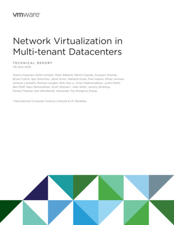
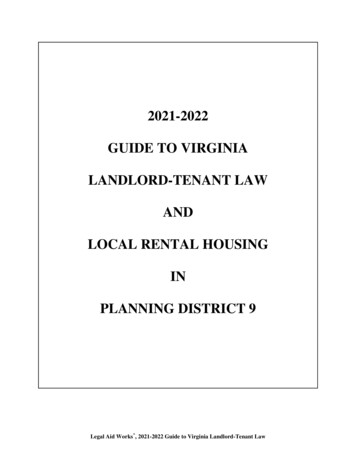
Logical ath 1LogicalEgressPortLogicalDatapath 2PhysicalDatapath (OVS)Source e 3: In NVP, controllers manage the forwarding state at alltransport nodes (hypervisors, gateways, service nodes). Transport nodesare fully meshed over IP tunnels (solid lines). Gateways connect thelogical networks with workloads on non-virtualized servers, and servicenodes provide replication for logical multicast/broadcast.DstFigure 2: The virtual switch of the originating host hypervisorimplements logical forwarding. After the packet has traversed thelogical datapaths and their tables, the host tunnels it across the physicalnetwork to the receiving host hypervisor for delivery to the destinationVM.2.2Service Node ClusterGatewayClusteris done via gateway appliances (again, x86-based hostsrunning virtual switching software); all traffic from thephysical network goes to the host hypervisor throughthis gateway appliance, and then can be controlled byNVP (and vice versa for the reverse direction). Gatewayappliances can be either within the MTD or at the tenant’sremote site. Figure 3 depicts the resulting arrangement ofhost hypervisors, service nodes and gateways, which wecollectively refer to as transport nodes.Virtualization ArchitectureThe network hypervisor supports these abstractions byimplementing tenant-specific logical datapaths on top ofthe provider’s physical forwarding infrastructure, andthese logical datapaths provide the appropriate controland packet abstractions to each tenant.In our NVP design, we implement the logical datapathsin the software virtual switches on each host, leveraging aset of tunnels between every pair of host-hypervisors (sothe physical network sees nothing other than what appearsto be ordinary IP traffic between the physical hosts). Thelogical datapath is almost entirely implemented on thevirtual switch where the originating VM resides; afterthe logical datapath reaches a forwarding decision, thevirtual switch tunnels it over the physical network tothe receiving host hypervisor, which decapsulates thepacket and sends it to the destination VM (see Figure 2).A centralized SDN controller cluster is responsible forconfiguring virtual switches with the appropriate logicalforwarding rules as tenants show up in the network.3While tunnels can efficiently implement logical pointto-point communication, additional support is neededfor logical broadcast or multicast services. For packetreplication, NVP constructs a simple multicast overlayusing additional physical forwarding elements (x86-basedhosts running virtual switching software) called servicenodes. Once a logical forwarding decision results in theneed for packet replication, the host tunnels the packetto a service node, which then replicates the packet toall host hypervisors that need to deliver a copy to theirlocal VMs. For deployments not concerned about thebroadcast traffic volume, NVP supports configurationswithout service nodes: the sending host-hypervisor sendsa copy of the packet directly to each host hypervisorneeding one.In addition, some tenants want to interconnect theirlogical network with their existing physical one. This2.3Design ChallengesThis brief overview of NVP hides many design challenges,three of which we focus on in this paper.Datapath design and acceleration. NVP relies on software switching. In Section 3 we describe the datapathand the substantial modifications needed to support highspeed x86 encapsulation.Declarative programming. The controller cluster isresponsible for computing all forwarding state and thendisseminating it to the virtual switches. To minimizethe cost of recomputation, ensure consistency in the faceof varying event orders, and promptly handle networkchanges, we developed a declarative domain-specificlanguage for the controller that we discuss in Section 4.Scaling the computation. In Section 5 we discuss theissues associated with scaling the controller cluster.After we discuss these design issues, we evaluate theperformance of NVP in Section 6, discuss related workin Section 7, and then conclude in Sections 8 and 9.3Virtualization Support at the EdgeThe endpoints of the tunnels created and managed by NVPare in the virtual switches that run on host hypervisors,gateways and service nodes. We refer to this collectionof virtual switches as the network edge. This sectiondescribes how NVP implements logical datapaths at thenetwork edge, and how it achieves sufficient data planeperformance on standard x86 hardware.3.13NVP does not control physical switches, and thus does notcontrol how traffic between hypervisors is routed. Instead, it isassumed the physical network provides uniform capacity acrossthe servers, building on ECMP-based load-balancing.Implementing the Logical DatapathNVP uses Open vSwitch (OVS) [32] in all transport nodes(host hypervisors, service nodes, and gateway nodes) toforward packets. OVS is remotely configurable by the3USENIX Association11th USENIX Symposium on Networked Systems Design and Implementation 205
NVP controller cluster via two protocols: one that caninspect and modify a set of flow tables (analogous toflow tables in physical switches),4 and one that allows thecontroller to create and manage overlay tunnels and todiscover which VMs are hosted at a hypervisor [31].The controller cluster uses these protocols to implementpacket forwarding for logical datapaths. Each logicaldatapath consists of a series (pipeline) of logical flowtables, each with its own globally-unique identifier.The tables consist of a set of flow entries that specifyexpressions to match against the header of a packet, andactions to take on the packet when a given expression issatisfied. Possible actions include modifying a packet,dropping it, sending it to a given egress port on the logicaldatapath, and modifying in-memory metadata (analogousto registers on physical switches) associated with thepacket and resubmitting it back to the datapath for furtherprocessing. A flow expression can match against thismetadata, in addition to the packet’s header. NVP writesthe flow entries for each logical datapath to a single OVSflow table at each virtual switch that participates in thelogical datapath. We emphasize that this model of alogical table pipeline (as opposed to a single table) is thekey to allowing tenants to use existing forwarding policieswith little or no change: with a table pipeline availableto the control plane, tenants can be exposed to featuresand configuration models similar to ASIC-based switchesand routers, and therefore the tenants can continue to usea familiar pipeline-based mental model.Any packet entering OVS – either from a virtualnetwork interface card (vNIC) attached to a VM, anoverlay tunnel from a different transport node, or aphysical network interface card (NIC) – must be sentthrough the logical pipeline corresponding to the logicaldatapath to which the packet belongs. For vNIC and NICtraffic, the service provider tells the controller clusterwhich ports on the transport node (vNICs or NICs)correspond to which logical datapath (see Section 5);for overlay traffic, the tunnel header of the incomingpacket contains this information. Then, the virtualswitch connects each packet to its logical pipeline bypre-computed flows that NVP writes into the OVS flowtable, which match a packet based on its ingress portand add to the packet’s metadata an identifier for the firstlogical flow table of the packet’s logical datapath. Asits action, this flow entry resubmits the packet back tothe OVS flow table to begin its traversal of the logicalpipeline.The control plane abstraction NVP provides internallyfor programming the tables of the logical pipelines islargely the same as the interface to OVS’s flow table andNVP writes logical flow entries directly to OVS, with twoimportant differences: Matches. Before each logical flow entry is written toOVS, NVP augments it to include a match over thepacket’s metadata for the logical table’s identifier.This enforces isolation from other logical datapathsand places the lookup entry at the proper stage ofthe logical pipeline. In addition to this forced match,the control plane can program entries that matchover arbitrary logical packet headers, and can usepriorities to implement longest-prefix matching aswell as complex ACL rules. Actions. NVP modifies each logical action sequenceof a flow entry to write the identifier of the nextlogical flow table to the packet’s metadata and toresubmit the packet back to the OVS flow table.This creates the logical pipeline, and also preventsthe logical control plane from creating a flow entrythat forwards a packet to a different logical datapath.At the end of the packet’s traversal of the logicalpipeline it is expected that a forwarding decision for thatpacket has been made: either drop the packet, or forward itto one or more logical egress ports. In the latter case, NVPuses a special action to save this forwarding decision inthe packet’s metadata. (Dropping translates to simply notresubmitting a packet to the next logical table.) After thelogical pipeline, the packet is then matched against egressflow entries written by the controller cluster according totheir logical destination. For packets destined for logicalendpoints hosted on other hypervisors (or for physicalnetworks not controlled by NVP), the action encapsulatesthe packet with a tunnel header that includes the logicalforwarding decision, and outputs the packet to a tunnelport. This tunnel port leads to another hypervisor forunicast traffic to another VM, a service node in the caseof broadcast and multicast traffic, or a gateway node forphysical network destinations. If the endpoint happens tobe hosted on the same hypervisor, it can be output directlyto the logical endpoint’s vNIC port on the virtual switch.5At a receiving hypervisor, NVP has placed flow entriesthat match over both the physical ingress port for that endof the tunnel and the logical forwarding decision presentin the tunnel header. The flow entry then outputs thepacket to the corresponding local vNIC. A similar patternapplies to traffic received by service and gateway nodes.The above discussion centers on a single L2 datapath,but generalizes to full logical topologies consistingof several L2 datapaths interconnected by L3 router5For brevity, we don’t discuss logical MAC learning or statefulmatching operations, but in short, the logical control plane canprovide actions that create new lookup entries in the logicaltables, based on incoming packets. These primitives allow thecontrol plane to implement L2 learning and stateful ACLs, in amanner similar to advanced physical forwarding ASICs.4We use OpenFlow [27] for this protocol, though any flowmanagement protocol with sufficient flexibility would work.4206 11th USENIX Symposium on Networked Systems Design and ImplementationUSENIX Association
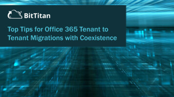
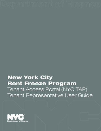
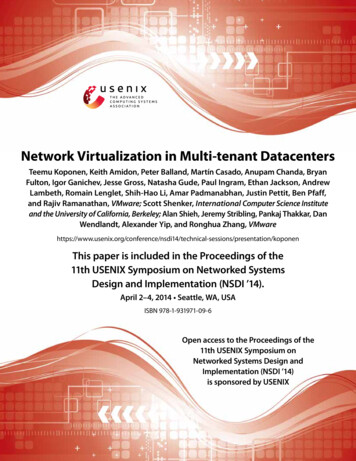
Logical Datapath 2Logical Datapath 1VMACLL2ACLACLL2L3Logical Datapath e 4: Processing steps of a packet traversing through two logical switches interconnected by a logical router (in the middle). Physical flowsprepare for the logical traversal by loading metadata registers: first, the tunnel header or source VM identity is mapped to the first logical datapath.After each logical datapath, the logical forwarding decision is mapped to the next logical hop. The last logical decision is mapped to tunnel headers.datapaths. In this case, the OVS flow table would holdflow entries for all interconnected logical datapaths andthe packet would traverse each logical datapath by thesame principles as it traverses the pipeline of a singlelogical datapath: instead of encapsulating the packet andsending it over a tunnel, the final action of a logicalpipeline submits the packet to the first table of thenext logical datapath. Figure 4 depicts how a packetoriginating at a source VM first traverses through alogical switch (with ACLs) to a logical router beforebeing forwarded by a logical switch attached to thedestination VM (on the other side of the tunnel). Thisis a simplified example: we omit the steps required forfailover, multicast/broadcast, ARP, and QoS, for instance.As an optimization, we constrain the logical topologysuch that logical L2 destinations can only be present atits edge.6 This restriction means that the OVS flow tableof a sending hypervisor needs only to have flows forlogical datapaths to which its local VMs are attached aswell as those of the L3 routers of the logical topology;the receiving hypervisor is determined by the logical IPdestination address, leaving the last logical L2 hop to beexecuted at the receiving hypervisor. Thus, in Figure 4, ifthe sending hypervisor does not host any VMs attached tothe third logical datapath, then the third logical datapathruns at the receiving hypervisor and there is a tunnelbetween the second and third logical datapaths instead.3.2new flow into userspace, where it is matched against thefull flow table, including wildcards, as many times as thelogical datapath traversal requires. Then, the userspaceprogram installs exact-match flows into a flow table inthe kernel, which contain a match for every part of theflow (L2-L4 headers). Future packets in this same flowcan then be matched entirely by the kernel. Existing workconsiders flow caching in more detail [5, 22].While exact-match kernel flows alleviate the challengesof flow classification on x86, NVP’s encapsulation of alltraffic can introduce significant overhead. This overheaddoes not tend to be due to tunnel header insertion, but tothe operating system’s inability to enable standard NIChardware offloading mechanisms for encapsulated traffic.There are two standard offload mechanisms relevant tothis discussion. TCP Segmentation Offload (TSO) allowsthe operating system to send TCP packets larger thanthe physical MTU to a NIC, which then splits them intoMSS-sized packets and computes the TCP checksums foreach packet on behalf of the OS. Large Receive Offload(LRO) does the opposite and collects multiple incomingpackets into a single large TCP packet and, after verifyingthe checksum, hands it to the OS. The combinationof these mechanisms provides a significant reductionin CPU usage for high-volume TCP transfers. Similarmechanisms exist for UDP traffic; the generalization ofTSO is called Generic Segmentation Offload (GSO).Current Ethernet NICs do not support offloading in thepresence of any IP encapsulation in the packet. That is,even if a VM’s operating system would have enabled TSO(or GSO) and handed over a large frame to the virtual NIC,the virtual switch of the underlying hypervisor would haveto break up the packets into standard MTU-sized packetsand compute their checksums before encapsulating themand passing them to the NIC; today’s NICs are simply notcapable of seeing into the encapsulated packet.To overcome this limitation and re-enable hardwareoffloading for encapsulated traffic with existing NICs,NVP uses an encapsulation method called STT [8].8 STTplaces a standard, but fake, TCP header after the physicalIP header. After this, there is the actual encapsulationheader including contextual information that specifies,among other things, the logical destination of the packet.The actual logical packet (starting with its Ethernetheader) follows. As a NIC processes an STT packet,Forwarding PerformanceOVS, as a virtual switch, must classify each incomingpacket against its entire flow table in software. However,flow entries written by NVP can contain wildcards for anyirrelevant parts of a packet header. Traditional physicalswitches generally classify packets against wildcard flowsusing TCAMs, which are not available on the standardx86 hardware where OVS runs, and so OVS must use adifferent technique to classify packets quickly.7To achieve efficient flow lookups on x86, OVS exploitstraffic locality: the fact that all of the packets belongingto a single flow of traffic (e.g., one of a VM’s TCPconnections) will traverse exactly the same set of flowentries. OVS consists of a kernel module and a userspaceprogram; the kernel module sends the first packet of each6We have found little value in supporting logical routersinterconnected through logical switches without tenant VMs.7There is much previous work on the problem of packetclassification without TCAMs. See for instance [15, 37].8NVP also supports other tunnel types, such as GRE [9] andVXLAN [26] for reasons discussed shortly.5USENIX Association11th USENIX Symposium on Networked Systems Design and Implementation 207
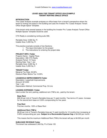
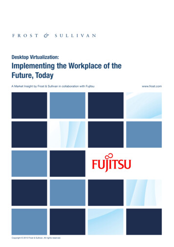
it will first encounter this fake TCP header, and considereverything after that to be part of the TCP payload; thus,the NIC can employ its standard offloading mechanisms.Although on the wire the STT packet looks likestandard TCP packet, the STT protocol is stateless andrequires no TCP handshake procedure between the tunnelendpoints. VMs can run TCP over the logical packetsexchanged over the encapsulation.Placing contextual information into the encapsulationheader, at the start of the fake TCP payload, allows for asecond optimization: this information is not transferredin every physical packet, but only once for each largepacket sent to the NIC. Therefore, the cost of this contextinformation is amortized over all the segments producedout of the original packet and additional information (e.g.,for debugging) can be included as well.Using hardware offloading in this way comes with asignificant downside: gaining access to the logical trafficand contextual information requires reassembling thesegments, unlike with traditional encapsulation protocolsin which every datagram seen on wire has all headers inplace. This limitation makes it difficult, if not impossible,for the high-speed forwarding ASICs used in hardwareswitch appliances to inspect encapsulated logical traffic;however, we have found such appliances to be rare inNVP production deployments. Another complication isthat STT may confuse middleboxes on the path. STTuses its own TCP transport port in the fake TCP header,however, and to date administrators have been successfulin punching any necessary holes in middleboxes in thephysical network. For environments where complianceis more important than efficiency, NVP supports other,more standard IP encapsulation protocols.ProvisionedConfiguration (2)ControllerLogical Control PlanesnlogLogical DatapathsNetwork HypervisorLocation information (1) and Forwarding State Figure 5: Inputs and outputs to the forwarding state computation processwhich uses nlog, as discussed in §4.3.the failed service no
virtualization abstractions to VMs, we build our archi-tecture around a network hypervisor that provides the right network virtualization abstractions. In this section we describe the network hypervisor and its abstractions. 2.1 Abstractions A tenant interacts with a network in two ways: the tenant's VMs send packets and the tenant configures