Transcription
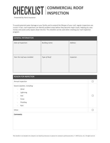
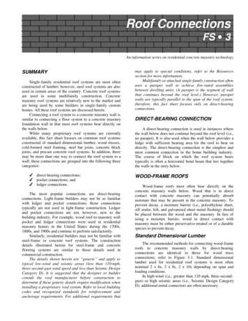
Roof ConnectionsFS 3 . An information series on residential concrete masonry technologySUMMARYSingle-family residential roof systems are most oftenconstructed of lumber; however, steel roof systems are alsoused in certain areas of the country. Concrete roof systemsare used in some multifamily construction. Concretemasonry roof systems are relatively new to the market andare being used by some builders in single-family customhomes. All these roof systems are discussed herein.Connecting a roof system to a concrete masonry wall issimilar to connecting a floor system to a concrete masonryfoundation wall in that most roof systems bear directly onthe walls below.While many proprietary roof systems are currentlyavailable, this fact sheet focuses on common roof systemsconstructed of standard dimensional lumber, wood trusses,cold-formed steel framing, steel bar joists, concrete blockjoists, and precast concrete roof systems. In addition, theremay be more than one way to connect the roof system to awall; these connections are grouped into the following threecategories:. direct-bearing connections;. pocket connections; and. ledger connections.The most popular connections are direct-bearingconnections. Light-frame builders may not be as familiarwith ledger and pocket connections; those connectionstypically are not used in light-frame construction. Ledgerand pocket connections are not, however, new to thebuilding industry. For example, wood roof-to-masonry wallpocket and ledger connections were used in residentialmasonry homes in the United States during the 1700s,1800s, and 1900s and continue to perform satisfactorily.Similarly, residential builders may not be familiar withsteel-frame or concrete roof systems. The constructiondetails illustrated herein for steel-frame and concreteflooring systems are similar to those details used incommercial construction.The details shown herein are “generic” and apply totypical low-wind and seismic areas (less than 110-mph,three-second-gust wind speed and less than Seismic DesignCategory D). It is suggested that the designer or builderconsult the roof manufacturer before construction todetermine if these generic details require modification wheninstalling a proprietary roof system. Refer to local buildingcodes and recognized standards for reinforcement andanchorage requirements. For additional requirements thatmay apply to special conditions, refer to the Resourcessection for more information.Multifamily or attached single-family construction oftenuses a parapet wall to achieve fire-rated assembliesbetween dwelling units. (A parapet is the segment of wallthat continues beyond the roof level.) However, parapetwalls are typically parallel to the span of the roof system;therefore, this fact sheet focuses only on direct-bearingconnections.DIRECT-BEARING CONNECTIONA direct-bearing connection is used in instances wherethe wall below does not continue beyond the roof level (i.e.,no parapet). It is also used when the wall below provides aledge with sufficient bearing area for the roof to bear ondirectly. The direct-bearing connection is the simplest andmost common connection in the home building industry.The course of block on which the roof system bearstypically is often a horizontal bond beam that ties togetherthe walls in the story below.WOOD-FRAME ROOFSWood-frame roofs most often bear directly on theconcrete masonry walls below. Wood that is in directcontact with concrete masonry can potentially absorbmoisture that may be present in the concrete masonry. Toprevent decay, a moisture barrier (i.e., polyethylene sheet,sill sealer, felt, and galvanized sheet metal flashing) shouldbe placed between the wood and the masonry. In lieu ofusing a moisture barrier, wood in direct contact withmasonry must be either preservative-treated or of a durablespecies to prevent decay.Standard Dimensional LumberThe recommended methods for connecting wood-frameroofs to concrete masonry walls by direct-bearingconnections are identical to those for wood trussconnections; refer to Figure 3-1. Standard dimensionallumber used for residential roof systems is most oftennominal 2 x 6s, 2 x 8s, 2 x 10s depending on span andloading conditions.In high-wind (i.e., greater than 110 mph, three-second gust) or high seismic areas (i.e., Seismic Design CategoryD), additional metal connectors are often necessary.
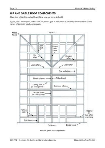
Wood TrussesSTEELWood trusses, also known as metal plate-connectedwood trusses, are popular for roof construction because oftheir competitive price, reduced labor requirements for roofframing, and ability to span long distances. Wood trussesare most often fabricated of nominal 2-inch standarddimensional lumber and designed by the truss manufacturerfor given span and loading conditions.Figure 3-1 illustrates some recommended methods forconnecting wood roof trusses to concrete masonry walls byusing direct-bearing connections. In high-wind (i.e., greaterthan 110 mph, three-second-gust) or high seismic areas (i.e.,Seismic Design Category D), an extra metal connector isoften necessary.Steel-frame roofs are common in commercialstructures. Steel-frame roofs are also used in multifamilyconstruction involving long spans or in heavily infestedtermite areas.Steel roofs most often bear directly on the walls below,although pocket and ledger connections may also be used.This section focuses on the direct-bearing connection, whichis the most common connection in residential construction.Cold-Formed Steel FramingCold-formed steel framing is typically truss-built fromC-shaped members, with width and depth dimensionssimilar to solid sawn lumber. The framing members areplaced at 16 or 24 inches on center.Figure 3-2 illustrates one recommended method forconnecting cold-formed steel-frame roof systems toconcrete masonry walls by using direct-bearing connections.In high-wind (i.e., greater than 110 mph, three-second-gust)or high seismic areas (i.e., Seismic Design Category D), anadditional metal connector is often necessary.Cold-formed steel trusses are also available frommanufacturers and are shipped to the site already assembledmuch like wood trusses; however, most steel trusses arebuilt on site. Figure 3-2 is also applicable to cold-formedsteel trusses.Figure 3-1: Wood Roof Truss (or Rafter) Direct-Bearing ConnectionWood I-JoistsWood I-joists are also popular because of theirconsistent quality and ability to span relatively longdistances. Wood I-joists resemble steel I-beams and aretypically manufactured using plywood or oriented strandboard for the web and solid sawn lumber for the flanges.The recommended methods for connecting wood Ijoists to concrete masonry walls are similar to those forstandard dimensional lumber; refer to Figure 3-1. Consultthe I-joist manufacturer for other possible methods ofconnecting wood I-joists to concrete masonry walls. In highwind (i.e., greater than 110 mph, three-second-gust) or highseismic areas (i.e., Seismic Design Category D), anadditional metal connector is often necessary.Figure 3-2: Cold-Formed Steel Roof Direct-Bearing ConnectionSteel Bar JoistsSteel bar joists are open web joists that are capable oflong spans. They are designed to bear directly on or to bepocketed into concrete masonry walls. In some areas, a steelledger angle is bolted to the masonry wall such that the steelbar joists bear on the steel angle. The steel angle ledgerconnection is sometimes used to eliminate the need for
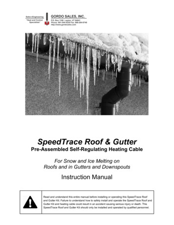
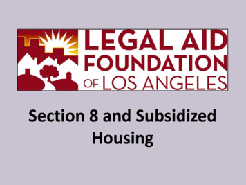
masons to form pockets in the wall, thereby reducing thecost of constructing concrete masonry walls. Steel bar joistsmay be used to construct either a flat or slightly sloped roofsystem.Figures 3-3 and 3-4 illustrate some recommendedmethods for connecting the steel bar joist to a concretemasonry wall. Steel bar joists typically require 3 to 4 inchesof bearing and should be fastened to the wall to provideanchorage for uplift and lateral forces.desired. Refer to the Resources section to obtainmanufacturer information and installation instructions.Figure 3-3: Steel Bar Joist Roof Direct-Bearing ConnectionFigure 3-5: Block Joist Roof SystemCONCRETEConcrete roofs are not common in single-familyresidential construction, but they are used in multifamilyresidential construction.Precast or poured-in-place concrete is typically used incommercial construction because it is capable of spanninglong distances and is resistant to rot and termite attack.Precast ConcreteFigure 3-4: Steel Bar Joist Roof Ledger ConnectionCONCRETE MASONRYA few currently available roof systems use concretemasonry while some rely on precast concrete joists or steelbar joists; however, other materials may be used inconjunction with the concrete masonry. One systemcurrently available is the Block Joist System, which relieson steel bar joists for support. The Block Joist System is acomposite system that is constructed with concrete blocksplaced side by side on patented steel bar joists. The barjoists rest on a ledge within the wall. Figure 3-5 illustrateshow the block and steel bar joists interlock to form thefinished roof deck. Some builders are using this type of roofsystem for patio roof deck applications where strength isPrecast concrete roof systems come in concretesegments in a variety of widths, thicknesses, and lengthsdepending on clear span and design loading conditions. Inresidential construction, roof segments are most often 8 inch-thick hollow core panels, 4 or 8 feet wide.Precast concrete segments are usually installed oncontinuous ledges in a concrete masonry wall that providesminimum bearing.Figure 3-6 illustrates some recommended methods forconnecting the precast concrete roof segments to a concretemasonry wall by using direct-bearing connections. Pocketconnections are not practical and ledger connections are notcommon; therefore, pocket and ledger connections are notdiscussed herein.
NAHB Research Center, Inc.400 Prince George’s BoulevardUpper Marlboro, Maryland 20774-8731 800.638.8556 http://www.nahbrc.orgNational Concrete Masonry Association (NCMA)2302 Horse Pen RoadHerndon, Virginia 20171-3499 703.713.1900 http://www.ncma.orgNorth American Steel Framing Alliance (NASFA)1726 M Street, N.W., Suite 601Washington, DC 20036-4523 202.785.2022 http://www.steelframingalliance.comPortland Cement Association (PCA)5420 Old Orchard RoadSkokie, Illinois 60077-1083 847.966.6200 http://www.portcement.orgPrecast/Prestressed Concrete Institute (PCI)175 West Jackson Boulevard, Suite 1859Chicago, Illinois 60604 312.786.0300 http://www.pci.orgFigure 3-6: Precast Concrete Roof SystemCONCLUSIONSGood construction details are vital to the satisfactoryperformance of residential structures. Several roof systemsare available in today’s market.The foregoing construction details are a compilation ofrecommended practices intended to ensure that residencesresist structural forces and loads. They also addressmovement and other related issues that compromise theintegrity of a well-constructed home. These recommendedpractices focus on some of the more common roofconnections used in single- and multi-family construction.RESOURCESAmerican Forest and Paper Association (AF&PA)1111 19th St., NW, Suite 800Washington, DC 20036 202.463.2700 http://www.afandpa.orgAmerican Plywood Association (APA)P.O. Box 11700Tacoma, Washington 98411 253.565.6600 http://www.apawood.orgBLOCK JOIST Company, LLC109 Ralston RoadRichmond, Virginia 23229 804.285.1250Steel Joist Institute (SJI)3127 10th Avenue, North Ext.Myrtle Beach, South Carolina 29577-6760 843.626.1995 http://www.steeljoist.comU.S. Department of Housing andUrban Development (HUD)451 Seventh Street, S.W., Suite 8132Washington, DC 20410 202.708.4370 http://www.hud.govPublications 800.245.2691 http://www.huduser.orgWood Truss Council of America (WTCA)6425 Normandy LaneMadison, Wisconsin 53719-1133 608.274.4849 http://www.woodtruss.com ACI 530/ASCE 5/TMS 402, Building CodeRequirements for Masonry Structures. AmericanConcrete Institute (ACI), American Society ofCivil Engineers (ASCE), and The Masonry Society(TMS), 1999. International Residential Code. International CodeCouncil, Inc. (ICC), Falls Church, Virginia, 2000(pending completion).
National Design Standard for Metal PlateConnected Wood Truss Construction. Truss PlateInstitute, Madison, Wisconsin, 1995. Prescriptive Method for Residential Cold-FormedSteel Framing, Third Edition. NAHB ResearchCenter, Inc., Upper Marlboro, Maryland, 1998. Metal Plate Connected Wood Truss Handbook.Wood Truss Council of America (WTCA), Madison,Wisconsin, 1994.
.
Finish AttachmentsFS 4An information series on residential concrete masonry technologySUMMARYFinishes on many of the homes built in the UnitedStates are vinyl, brick veneer, wood, or stucco on theexterior and drywall or plaster on the interior. Althoughmost homes in the United States are light-frame, these samefinishes can also be installed on concrete masonry homes. Insome cases, the finish system can be installed more quicklyand less expensively than on light-frame homes. Homebuilders, however, may be unfamiliar with techniques forfastening the various finishes to concrete masonry walls.This fact sheet focuses on general attachment details forcommon finish materials to concrete masonry walls.Specific tools and fasteners used to connect the finishes tothe concrete masonry wall are covered in Fact Sheet 7(FS 7). Leaving the concrete masonry wall exposed is alsodiscussed herein.Also of interest are requirements for moisture control(i.e., weather barrier) on masonry walls. Where weatherbarriers are typically required, it is shown in the illustration.Weather-barriers allow moisture vapors to escape. Moisture,while not posing a threat to the strength of concretemasonry, may adversely affect finish and insulation systemsas well as utilities. Refer to the specific finishmanufacturer’s technical information to determine whattypes of weather barriers, if required, are permitted.As with light-frame construction, proper flashing isnecessary to prevent water intrusion. Flashing should beinstalled around openings before the installation of finishsystems.The details shown herein are “generic”. Many finishmanufacturers have warranties that become void ifinstallation does not comply with manufacturers’installation instructions. The illustrations in this fact sheetdo not include guidance on the installation of flashing,window and door selection and installation, and caulkingsince it is not only dependent on the finish system, but alsothe specific finish manufacturer. As a result, it is suggestedthat the designer or builder consult the finish manufacturerbefore construction to determine what modifications arerequired.construct above-grade walls, builders must consider how toattach finishes to concrete masonry walls. However,exposed concrete masonry need not be gray, flat, or 8- by16-inch modules. Today, concrete masonry units aremanufactured in a wide variety of shapes, sizes, colors, andtextures. Figure 4-1 illustrates various concrete blocks thatare now available.Units are also readily available in nominal 4- or 8-inchheights and nominal 8- or 16-inch lengths. These types ofblock are available as hollow (shown) or as solid units.Hollow units are used to construct structural walls and areavailable in larger widths. Hollow and solid units areinstalled in the same manner as traditional gray concreteblocks.EXPOSED CONCRETE BRICK OR BLOCKThe size of a “traditional” concrete masonry unit isnominally 4, 6, 8, 10, or 12 inches wide, 8 inches high, and16 inches long. The units are typically gray with a flat finishand are usually hollow or sometimes solid. These“traditional” units are often used in residential constructionto construct foundation walls. When units are used toFigure 4-1: Hollow Concrete Masonry UnitsMulti-colored, multitextured units are more attractive todesigners, home owners, and builders than the “traditional”
gray units. A color may be used for an entire wall or designsmay be created by using more than one color.Concrete masonry units available are split-faced,slumped, fluted, ribbed, and scored. Split-faced blocks aresplit lengthwise by a machine to produce a rough, stone-liketexture. Slump blocks are manufactured by squeezing theblock after it is formed to create a bulging effect. Fluted,ribbed, and scored blocks are formed with vertical flutes,ribs, or striations that align during wall construction to givethe appearance of a wall constructed of smaller units. Referto the Resources section for more information on availableshapes and sizes.Concrete bricks may be manufactured at 3-5/8 incheswide by 2-1/4 inches high by 7-5/8 inches long - dimensions identical to clay brick. Concrete brick may alsobe manufactured at 3-5/8 inches wide by 2-1/4 inches highby 15-5/8 inches long. Concrete brick veneer supports onlyits own weight and is anchored to a concrete masonry wallby corrosion-resistant metal ties. Refer to the local buildingcode for the horizontal and vertical spacing requirements forbrick metal ties. Figures 4-2 and 4-3 illustrate methods ofanchoring concrete brick veneer to concrete masonry walls.Conventional corrugated brick ties may also be used in lieuof the ladder-type wall tie shown in Figures 4-2 and 4-3.Figure 4-3: Brick Veneer (Composite Wall)Figure 4-2: Brick Veneer (Cavity Wall)Concrete brick is also available as a patented, tongue and-groove interlocking concrete brick system installed in amanner similar to bevel siding. Figures 4-4a and 4-4billustrate the interlocking concrete brick and its installation.Refer to the Resources section to obtain manufacturerinformation.In single-wythe concrete masonry wall constructionexposed to the weather, a water repellent is suggested.Water repellents provide resistance to wind-driven rain andprotect the masonry from efflorescence and staining.Figure 4-4a: Novabrik TM by the Allan Block CorporationWater repellents may be surface applied after the wallis constructed or added during the manufacturing process asan admixture integral to the unit. Water repellents, whethersurface applied or integral, come in a variety of colors,textures, and finishes (i.e., matte or glossy).If used in the manufacture of masonry units, integralwater repellents, should also be added to the mortar at thejob site. Surface-applied water repellents should always bewater vapor permeable, which means that they should allowwater vapor in the wall to escape. If the water repellent does
not allow the concrete masonry wall to “breathe”, moisturecan build up and cause the repellent to blister and peel.Surface repellents may be applied in addition to using anintegral water repellent; however, check with the blockmanufacturer as well as the water-repellent manufacturer toensure that that the repellents are compatible.Figure 4-4b: Novabrik TM by the Allan Block CorporationCLAY BRICK VENEERClay brick masonry has traditionally been popular as aveneer on wood frame homes. Common face bricks aretypically 3-5/8 inches wide by 2-1/4 inches high by 7-5/8inches long. Other sizes are available in some regions. Theunits can be either hollow or solid and come in manydifferent shapes, sizes, textures, and colors.Clay brick veneer supports only its own weight and ismost commonly supported by a ledge in the foundationwall. Corrosion-resistant metal ties secure the veneer toconcrete masonry walls. Refer to the local building code forhorizontal and vertical spacing requirements for brick metalties. Figures 4-2 and 4-3 illustrate methods for anchoringclay brick veneer to a concrete masonry wall. Conventionalcorrugated brick ties may also be used in lieu of the laddertype wall tie shown in Figures 4-2 and 4-3.Clay brick is also manufactured as a “thin brick”,measuring 1/2-inch wide, 2-1/4 inches high, and 7-5/8inches long. These brick units are typically fastened to theconcrete masonry wall with adhesive; mortar is then appliedwith a mortar gun between the bricks. The resulting wall hasthe appearance of a traditional brick veneer wall but at lessexpense.Some systems that use the 1/2-inch-thick brick alsoprovide a patented backer board that is fastened to theconcrete masonry wall. The brick is then adhered to thebacker board and the mortar joints filled with a mortar gun.The patented backer board typically provides some variationof a horizontal 3/8-inch spacer to allow faster and moreuniform placement of the bricks. Figure 4-5 illustrates a 1/2 inch-thick clay brick veneer system on a concrete masonrywall.Figure 4-5: Patented Thin Brick VeneerSTONE VENEERUnless a home is a historic or custom residence, stoneis typically used as a veneer on the entry facade, or as anaccent, such as for a fireplace. Stone veneer is available inthin units, between 1 and 3 inches, and in a variety of colors,textures, sizes, and shapes. Figures 4-6 and 4-7 illustratetwo methods of stone veneer installation.Depending on the thickness and weight of each unit,stone veneer is typically installed in a manner similar tobrick on a structural concrete masonry wall. One end of acorrosion-resistant anchor is inserted into the mortar joint ofthe stone and the other end into the mortar joint of theconcrete masonry wall. For thinner (i.e., 1/4- to 5/8-inch thick) and lighter stone veneer, a thin bed of mortar isapplied directly to the surface of the concrete masonry wall.The stone veneer is placed in the bed of mortar and thejoints between the stone units are grouted. Figure 4-6illustrates the method of attaching natural stone veneer to aconcrete masonry wall.Cultured stone veneer is also available and is typicallyless expensive and lighter in weight than natural stone.Cultured stone veneer is cast in molds by using Portlandcement, light-weight natural aggregates, and color pigmentsto produce units that look and feel like natural stone. Thelightweight cultured stone units can be fastened to theconcrete masonry wall with a thin layer (i.e., 3/8-inch-thick)of mortar. If the stone selected requires joints between eachstone unit, the joints are then filled with mortar. Figure 4-7illustrates cultured stone veneer on a concrete masonry wall.
WOOD SIDINGFigure 4-6: Stone VeneerWood siding has been used for more than one hundredyears in the United States and has traditionally taken theform of lap-board or bevel siding. It is manufactured tostandard sizes and made by sawing plain-surfaced boards ata diagonal to produce two wedge-shaped pieces. The sidingis about 3/16 inch thick at the thin edge and 1/2 to 3/4 inchthick at the other edge, depending on the width of the piece.Refer to Figure 4-8, which illustrates the attachment ofwood siding to a concrete masonry wall.Plain bevel siding is lapped (hence the term lap-board)so it will shed water. A minimum lap of 1 inch is used for 6 inch widths, while 8- and 10-inch siding should lap about 1 1/2 inches.Vertical wood siding is also commonly used. It may beplain-surfaced matched boards, pattern-matched boards, orsquare-edge boards covered at the joint with a batten strip.Plywood siding is common. Panel sizes are 4 feet wideby 8, 9, and 10 feet long. To eliminate horizontal joints,plywood is installed vertically. Once installed, plywoodlapped sidings may look the same as regular bevel siding.Wood siding should not be fastened directly to concretemasonry walls. Typically, preservative-treated nominal 1 x3 wood furring strips are fastened at 16 or 24 inches oncenter perpendicular to the direction of the wood siding. Thewood siding is then fastened to the furring strips with zinccoated steel, aluminum, or other noncorrosive nails. Plainsteel-wire nails with large heads are not recommendedbecause they produce unsightly rust spots on most paintsand stains.ALUMINUM SIDINGAluminum siding is factory finished with baked-onenamel and, in appearance, closely resembles painted woodsiding. A variety of horizontal and vertical panel styles inboth smooth and textured designs are produced with varyingshadow lines and size of face exposed to the weather. Panelsare fabricated with prepunched nail and vent holes and aspecial interlocking design.Aluminum siding is attached to concrete masonry wallsin a manner similar to wood siding; refer to Figure 4-8.Typically, preservative-treated furring strips are fastened at16 or 24 inches on center perpendicular to the direction ofthe aluminum siding. The aluminum siding is then fastenedto the furring strips with zinc-coated steel, aluminum, orother noncorrosive nails; however, the siding should not befastened tightly to the furring strips to allow for expansionand contraction. Each aluminum strip or piece hooks intothe course below and is secured in place by nailing along theslotted top edge. Panels are designed with moisture-proofinterlocking joints. A special corner piece covers the endsand allows for expansion and contraction resulting fromtemperature changes.Aluminum siding is usually installed with a backerboard or insulation board behind each panel. The insulationboard adds rigidity and strength as well as insulating valueto the aluminum. Many manufacturers produce sidingproducts that include special designs or patented devices toFigure 4-7: Cultured Stone Veneer
simplify installation. Figure 4-8 illustrates the attachment ofaluminum siding to a concrete masonry wall.adds rigidity and strength as well as insulating value to thevinyl.Many manufacturers produce siding products thatinclude special designs or patented devices to simplifyinstallation.FIBER-CEMENT SIDINGFiber-cement siding is fabricated of Portland cement,sand, cellulose fiber, and water; some manufacturers mayadd other materials. Fiber-cement siding closely resemblespainted wood siding and is available factory primed fromsome manufacturers.A variety of horizontal and vertical panel styles in bothsmooth and textured designs are produced with varyingshadow lines and size of face exposed to the weather. Fibercement siding may be lapped or installed vertically withbattens. It is typically 5/16 inch thick. Panels are availablein 4 feet by 8, 9, or 10 feet.Fiber-cement siding is attached to a concrete masonrywall in a manner similar to wood siding; refer to Figure 4-8.Typically, preservative-treated furring strips are fastened amaximum of 24 inches on center perpendicular to thedirection of the fiber-cement siding. The fiber-cement sidingis then fastened to the furring strips with zinc-coated steel,aluminum, or other noncorrosive nails.Fiber-cement siding does not require a backer board orinsulation board behind each panel for added rigidity;however, a backer board may be installed for thermal value.STUCCOFigure 4-8: Wood, Aluminum, Vinyl, or Fiber-Cement SidingVINYL SIDINGVinyl siding is fabricated of a rigid polyvinyl chloridecompound that is tough and durable. It is extruded intovertical and horizontal siding and accessories. It resemblespainted wood siding.A variety of horizontal and vertical panel styles in bothsmooth and textured designs are produced with varyingshadow lines and size of face exposed to the weather. Panelsare fabricated with prepunched nail and vent holes and aspecial interlocking design.Vinyl siding is attached to a concrete masonry wall in amanner similar to wood or aluminum siding; refer to Figure4-8. Typically, preservative-treated furring strips arefastened at 16 or 24 inches on center perpendicular to thedirection of the vinyl siding. The vinyl siding is thenfastened to the furring strips with zinc-coated steel,aluminum, or other noncorrosive nails; however, the sidingshould not be fastened tightly to the furring strips to allowfor expansion and contraction. Each vinyl strip or piecehooks into the course below and is secured in place bynailing along the slotted top edge. Panels are designed withmoisture-proof interlocking joints. A special corner piececovers the ends and allows for expansion and contractionresulting from temperature changes.Vinyl siding is usually installed with a backer board orinsulation board behind each panel. The insulation boardStucco is a finish composed mainly of Portland cement,sand, water, lime, and/or acrylic. Figure 4-9 illustrates theapplication of stucco to the exterior of a concrete masonrywall.The three categories of stucco are as follows:. Portland cement stucco;. polymer-modified stucco; and. polymer-based stucco.Portland cement stucco (PC) is sometimes referred to astraditional stucco and contains no acrylic. Polymer-modifiedstucco (PM) is sometimes referred to as hard-coat stuccoand contains a minimal amount of acrylic. Polymer-basedstucco (PB) is sometimes referred to as soft-coat stucco andcontains approximately 50 percent acrylic. Acrylic givesstucco some flexibility and water resistance; therefore,stuccoes containing acrylic are more popular in areassubject to severe freeze-thaw cycles.Stucco is applied to a concrete masonry wall in two orthree layers or coats. The first coat is termed the scratch coatand is approximately 1/4 to 3/8 inch thick. The second coatof a three-coat system is termed the brown coat and isapproximately 3/8 to 1/2 inch thick. The third coat of athree-coat system or the second coat of a two-coat system istermed the finish coat and is approximately 1/4 inch thick.The finish coat may be tinted by adding color, or the surfacemay be painted with a suitable material.
EIFS is available as either a drainable system or asystem without drainage. Figures 4-10 and 4-11 illustratedrainable and undrainable EIFS, respectively. Drainablesystems have an additional material layer between theinsulation and the concrete masonry wall to allow water toflow behind the finish system into weep holes below. Somedrainable systems use patented rigid insulation with drainchannels molded onto the back face of the insulation. Thechannels eliminate the need for installing separate drainmaterial. At the top of openings, bottom of walls, etc., weepholes are created to allow any accumulated water to exit thewall.Fasteners require
While many proprietary roof systems are currently available, this fact sheet focuses on common roof systems constructed of standard dimensional lumber, wood trusses, cold-formed steel framing, steel bar joists, concrete block joists, and precast concrete roof systems. In addition, there may be more than one way to connect the roof system to a