Transcription
Residential Gas FurnacesInstallation InstructionsG6RX Series 80 High Efficiency Upflow/Horizontal80 Upflow/Horizontal! WARNING:Improperinstallation,adjustment, alteration,service, or maintenance cancause injury or propertydamage. Refer to thismanual. For assistance oradditional informationconsult a qualified installer,service agency, or the gassupplier.FOR YOUR SAFETYDo not store or use gasolineor other flammable vaporsand liquids in the vicinity ofthis or any other appliance.FOR YOUR SAFETYWHAT TO DO IF YOU SMELL GAS Do not try to light anyappliance. Do not touch any electricalswitch; do not use anyphone in your building. Immediately call your gassupplier from a neighbor'sphone. Follow the gassupplier's instructions. If you cannot reach your gassupplier, call the firedepartment. Extinguish any open flame.DO NOT DESTROY. PLEASE READ CAREFULLY AND KEEP IN A SAFE PLACE FOR FUTURE REFERENCE.These instructions are primarily intended to assist qualified individuals experienced in the proper installation of thisappliance. Some local codes require licensed installation/service personnel for this type of equipment. Read allinstructions carefully before starting the installation.
Table of ContentsFurnace Specifications . 3Capacities-Furnace Airflow Data . 4Installation Requirements . 4Venting and Combustion Air Requirements . 6General . 6Installation in an Unconfined Space . 6Installation in a Confined Space. 6Horizontal Furnace Installation . 6Air From Inside . 7Outdoor Air Using Vertical Ducts . 7Air Directly Through an Exterior Wall . 8Outdoor Air Using A Crawl Space and Ventilated Attic . 8Outdoor Air Through Horizontal Ducts . 8Venting Requirements . 9General . 9Category I - Common Venting . 9Category III - Horizontal Venting . 9Location of Outdoor Terminations . 11Horizontal Installation . 11Flexible Vent Systems . 12Circulating Air Supply . 12General . 12Return Air . 12Gas Supply and Piping . 13General . 13Leak Check . 14Conversion . 14High-Altitude Application . 14Natural Gas High Altitude Conversion . 15LP/Propane Gas Sea Level and High Altitude Conversion . 15Electrical Wiring . 16General . 16Line Voltage Wiring . 16Low Voltage Wiring . 16Start-up & Adjustments . 18General . 18Start-Up Procedures . 18Verifying and Adjusting Firing Rate . 18Verifying and Adjusting Temperature Rise . 19Verifying Burner Operation . 20Verifying Operation of Supply Air Limit Switch . 20Wiring Diagram . 21Description of Components . 22Maintenance . 23Vent System . 23Air Filter(s) . 23Lubrication . 23Blower Compartment . 23Heat Exchanger and Burner Maintenance . 23Cleaning of Flue Passages . 23Cleaning of Burners . 24System Operation Information . 24General . 24Sequence of Operation . 25Heating Mode . 25Cooling Mode . 25Fan Mode . 25Furnace Fails to Operate . 25Twinning . 26Installation/Performance Checklist . 27
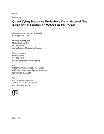
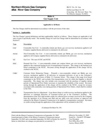
FURNACE SPECIFICATIONS - Upflow/Horizontal ModelsA23 3/43/4FLUEOUTLETUnit Shown in Upflow PositionRotate 90 Clockwise or Counter Clockwisefor Horizontal ApplicationB3/4C19 3/43/43/425 1/811/2 X 31/2 Cut-out forGas Connection11/2 X 31/2 Cut-out forGas Connection7/8Cut-out forElectric Connection7/843Cut-out for ElectricConnection3325 5/8301/425 1/4251/4ReturnAir Opening(Side)157/811/420 1/21 1/42327 5/8DReturn Air Opening(Bottom)231 1/4Figure 1. Furnace DimensionsFURNACE DIMENSIONS ANDSHIPPING n.)(in.)ShippingFlue Outlet Weight(in.)(lbs)D(IN.)G6RX045(E)-08 45,00014 1/412 3/43 1/4312311 3/4G6RX072(E)-12 72,00014 1/412 3/43 3/4413511 3/4G6RX096(E)-16 96,00019 3/418 1/43 3/4416317 1/4G6RX120(E)-20 120,00022 1/2213 3/4418220Table 1. Furnace Dimensions and Shipping Weights3
INSTALLATION REQUIREMENTSRequirements and CodesThis furnace must be installed in accordance with theseinstructions and all applicable local building codes.! WARNING:This furnace is not approved for installation inmobile homes. Installation in a mobile homecould cause fire, property damage, and/orpersonal injury.LocationThese gas furnaces are shipped ready for installation in theupflow or horizontal right or left positions. The furnace mustbe installed on a level surface, located as close to the vent(or chimney) and as close to the center of the air distributionsystem as possible. See Table 1 for overall dimensionsto determine the required clearances in hallways, doorways,stairs, etc. to allow the furnace to be moved to theinstallation point. The furnace must be installed so that allelectrical components are protected from water. Thefurnace must be installed upstream from a refrigerationsystem. This furnace is not to be used for temporaryheating of buildings or structures under construction.Access for positioning and servicing the unit must beconsidered when locating unit. 24 inches is the minimumrequired clearance from the front of the unit for servicingit. 30 inches is the minimum required clearance from thefront of the unit for positioning it. 36 inches is therecommended clearance from the front of the unit.Please note that a panel or door can be located such thatthe minimum clearance on the rating plate is satisfied, butthat panel or door must be removable and allow theappropriate clearance for your installation.This furnace is certified for use on wood flooring. Thisfurnace must not be installed directly on carpeting, tile, orany combustible material other than wood flooring.VENTING AND COMBUSTIONCAPACITIES —Furnace Airflow DataUpflow Furnace Airflow DataFurnaceModel 161/2G***-120C-203/4MotorSpeedHigh *MediumLow **High *MediumLow **High *Med-High **Med-LowLowHigh *Med-High **Med-LowLow* Factory wired cooling speed tap**Factory wired heating speed tap- Not 960178014401160950Rise3646505755645062-External Static Pressure (Inches Water 546662735568-Temperature rises given are approximate values.Actual rises may vary.Table 2. Furnace Airflow 101040760
Clearances to CombustiblesThe minimum clearances to combustible material are listed in Table 3. See the furnace name plate, located inside thefurnace cabinet, for specific model number and clearance information.FurnacesUPFLOW APPLICATIONHORIZONTAL EBOTTOMBOTTOMUPFLOW INSTALLATION CLEARANCESVentConnectorTypeLEFT SIDERIGHT SIDEVENTBACKBOTTOMTOPFRONTStandard SingleWall Metal Vent0"5"6"0"0"1"4"*Type B-1 DoubleWall Metal Vent0"0"1"0"0"1"4"** Allow 24" minimum clearance for servicing.HORIZONTAL INSTALLATION CLEARANCESVentConnectorStandard SingleType B Double WallTypeWall Metal VentMetal VentLEFT SIDE1"1"RIGHT NT* Allow 24" minimum clearance for service.Table 3. Minimum Clearances to Combustible Material5
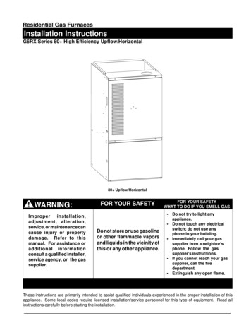
AIR REQUIREMENTSGeneralProvisions must be made in the installation of this furnaceto provide an adequate supply of air for combustion.Instructions for determining the adequacy of an installationare found below. Consult local codes for specialrequirements.If the furnace is operated with inadequate air for combustionone of the flame roll-out switches located in the burnercompartment or the vent switch will open, turning off thegas supply to the burners. These safety devices aremanually reset switches. DO NOT install jumper wiresacross these switches to defeat their function. DO NOTreset a switch without identifying and correcting the faultcondition. If a switch must be replaced, use only thecorrect part specified in the Replacement Parts List.Air openings in the furnace door, warm air registers, andreturn air grilles must not be restricted.To maximize heat exchanger life, the combustion air must! CAUTION:Combustion air must not be drawn from acorrosive atmosphere.be free of chemicals which form corrosive acidic compoundsin the combustion gases. Some examples of thesechemicals are chlorine, fluorine, and sulphur. Somecommon sources of these chemicals are detergents,bleaches, aerosol sprays, cleaning solvents, and a widevariety of commercial and household products.When installing a furnace in a commercial building or in alaundry room or workshop of a residence, it may benecessary to provide outside air to the furnace forcombustion.45,000 Btuh input and a furnace rated at 75,000 Btuhrequires a volume of 6,000 cubic feet [50 x (45 75) 6,000] to be considered unconfined. If the space has an 8foot ceiling, the floor area of the space must be 750 squarefeet (6,000 / 8 750). In general, a furnace installed in anunconfined space will not require outside air for combustion.However, in “tight” buildings (with weather stripping andcaulk to reduce infiltration), it may be necessary to provideoutside air to ensure adequate combustion and venting,even though the furnace is located in an unconfined space.Installation In A Confined SpaceA confined space is an area with volume less than 50 cubicfeet per 1,000 Btuh of the combined input rates of allappliances drawing combustion air from that space.Furnace closets, small equipment rooms and garages areconfined spaces. Furnaces installed in a confined spacewhich supply heated air to areas outside the space mustdraw return air from outside the space and must have thereturn air ducts tightly sealed to the furnace. A confinedspace must have two openings into the space forcombustion air. One opening must be within 12inches of the ceiling, and the other must be within 12inches of the floor. The required sizing of these openingsis determined by whether inside or outside air is used tosupport combustion, the method by which the air is broughtto the space, and by the total input rate of all appliances inthe space.Horizontal Furnace InstallationThese furnaces can be installed horizontally in an attic,basement, crawl space or alcove. It can be suspendedfrom a ceiling in a basement or utility room in either a rightto left airflow or left to right airflow. (See Figures 2 and 3.)If the furnace is to be suspended from the ceiling, it will beInstallation In An Unconfined Space! WARNING:Furnace installation using methods other thanthose described in the following sections mustcomply with all applicable local codes toprovide sufficient combustion air for thefurnace.An unconfined space is an area including all rooms notseparated by doors with a volume greater than 50 cubicfeet per 1,000 Btuh of the combined input rates of allappliances which draw combustion air from that space.For example, a space including a water heater rated atFigure 2. Horizontal InstallationSuspended in Attic or Crawl Space6
necessary to use steel straps around each end of thefurnace. These straps should be attached to the furnacewith sheet metal screws and to the rafters with bolts. Thefurnace could also be suspended by an angle iron framebolted to the rafters. (See Figure 2.)Vent orChimneyOpenings toadjacent space.Each opening mustbe at least 100 sq. in.or 1 sq. in. per 1000Btuh of total inputrating, whichever isgreater. See minimumarea per table.Keep all insulating materials away from the louvered door.Insulating materials may be combustible.These furnaces may be installed directly on combustiblewood flooring or supports, if type "B-1" vent pipe is used(See Figure 3). It is recommended for further reduction offire hazard that cement board or sheet metal be placedbetween the furnace and the combustible floor and extend12 inches beyond the front of the louvered door.For venting follow the guidelines specified under theventing section.Air From Inside (See Figure 4)Note: LineContact is PermissibleGas Inlet12" Max.Furnace12" Max.Water HeaterMinimumFree Area(Each Opening)100 sq. in.100 sq. in.100 sq. in.100 sq. in.120 sq. in.140 sq. in.160 sq. in.Total InputRating ,000Round DuctDiameter12"12"12"12"13"14"15"Figure 4. Equipment in a Confined Space with allCombustion Air Drawn from the InsideType “B” VentCoil nLouver Door(See Figure 5)If combustion air is taken from outdoors through verticalducts, the openings and ducts must have a minimum freearea of one square inch per 4,000 Btuh of total applianceinput. In installations drawing combustion air from aventilated attic, both air ducts must extend above the atticinsulation.If the unit is installed in an area with an exhaust fan, provideFigure 3. Horizontal installation on a PlatformVentilation Louvers ateach end of atticVent orChimneyOutlet Air Duct mustbe at least 1 sq. in.per 4,000 Btuh oftotal input rating.! WARNING:Furnaces installed with combustion air drawnfrom a heated space which includes exhaustfans, fireplaces, or other devices that mayproduce a negative pressure should beconsidered confined space installations.If combustion air is taken from the heated space, the twoopenings must each have a free area of at least onesquare inch per 1,000 Btuh of total input of all appliancesin the confined space, but not less than 100 squareinches of free area. For example, if the combined inputrate of all appliances is less than or equal to 100,000 Btuh,each opening must have a free area of at least 100 squareinches. If the combined input rate of all appliances is120,000 Btuh, each opening must have a free area of atleast 120 square inches.Outdoor Air Using Vertical DuctsInlet and Outlet Ductsmust extend aboveattic insulation.AtticInsulationInlet Air Duct mustbe at least 1 sq. in.per 4,000 Btuh oftotal input rating.Furnace12" MaxWater Heatera. All Combustion Air from Ventilated Attic.Total InputRating (Btu/hr)MinimumFree Area(Each Opening)Round DuctDiameterFigure 5. Equipment in a Confined Space with allCombustion Air Drawn from the Outsidethrough Vertical Ducts7
sufficient ventilation to prevent negative pressures fromoccurring in the room.Ventilation Louvers ateach end of atticVent orChimneyThe combustion air openings must not be restricted in anymanner.Attic InsulationOutlet Air Ductmust be at least1 sq. in. per 4000Btuh of total inputrating. Must extendabove attic insulation.Air Directly Through An Exterior Wall! CAUTION:Do not supply combustion air from an atticspace that is equipped with power ventilationor any other device that may produce anegative pressure.(See Figure 6)If combustion air is provided directly through an exteriorwall, the two openings must each have free area of at leastone square inch per 4000 Btuh of total appliance input.Outdoor Air Using a Crawl Space and VentilatedVent orChimneyEach openingto outsidemust be at least1 sq. in. per 4000Btuh of total inputrating.Inlet Air Duct mustbe at least 1 sq. in.per 4,000 Btuh oftotal input rating.Water HeaterVentilation Louvers forunheated crawl spaceCrawl SpaceFigure 7. Equipment in a Confined Space with AllCombustion Air Drawn from aCrawl Space and Ventilated AtticIf combustion air is taken from outdoors through horizontalducts, the openings and ducts must have a minimum freearea of one square inch per 2,000 Btuh of total applianceinput.If the unit is installed in an area with an exhaust fan, providesufficient ventilation to prevent negative pressures fromoccurring in the room.The combustion air openings must not be restricted in anymanner.12" Max---FurnaceThe venting system should be designed to have theFurnaceVent orChimneyEach openingto outsidemust be at least1 sq. in. per 2000Btuh of total inputrating.Total InputRating 00Water HeaterMinimumFree Area(Each Opening)10 sq. in.15 sq. in.20 sq. in.25 sq. in.30 sq. in.35 sq. in.40 sq. in.Round DuctDiameter4"5"5"6"6"7"8"Figure 6. Equipment in a Confined Space with allCombustion Air Drawn from the Outsidethrough Exterior WallAttic (See Figure 7)When directly communicating with the outdoors, eachopening shall have a minimum free area of 1 square inchper 4,000 Btuh of total appliance input. The openings shallcommunicate directly, or by ducts, with the outdoor spaces(crawl or attic) that freely communicate with the outdoors.Outdoor Air Using Horizontal Ducts (See Figure 8)812" Max---Air Duct------12" Max-----Air Duct---Furnace--12" MaxTotal InputRating ,000Water HeaterMinimumFree Area(Each Opening)20 sq. in.30 sq. in.40 sq. in.50 sq. in.60 sq. in.70 sq. in.80 sq. in.Round DuctDiameter5"6"7"8"9"10"10"Figure 8. Equipment in a Confined Space with allCombustion Air Drawn from the Outside throughHorizontal Ducts
VENTING REQUIREMENTSGeneralThis furnace must be vented in compliance with theinstructions provided below, and with the Category IVenting Tables provided with the furnace.This furnace must never be vented to a chimney flueservicing a fireplace or other appliance designed to burnsolid fuel. If the furnace vent is to be connected to achimney serving a fireplace, the fireplace must be sealedoff from the chimney.The furnace vent, if metal, may be insulated if local codesallow. Any part of the vent system, metal vent only, notexposed to weather, but which are exposed to ambienttemperatures below 35 F must be insulated to preventcondensation. All vent insulation shall be foil backedfiberglass of one inch minimum thickness.Category I - Common VentingWhen an existing furnace is removed from a ventingsystem serving other appliances, the venting system islikely to be too large to properly vent the remainingappliances.The following steps shall be followed with each individualappliance connected to the venting system placed inoperation, while all other appliances connected to theventing system are not in operation:(a) Seal any unused openings in the venting system.(b) Inspect the venting system for proper size andhorizontal pitch. Determine that there is no blockageor restriction, leakage, corrosion or other deficiencieswhich could cause an unsafe condition.(c) In so far as is practical, close all building doors andwindows and all doors between the space in whichthe appliance(s) connected to the venting system arelocated and other spaces of the building. Turn onclothes dryers and any appliance not connected tothe venting system. Turn on any exhaust fans, suchas range hoods and bathroom exhausts, so theyshall operate at maximum speed. Do not operate asummer exhaust fan. Close fireplace dampers.(d) Follow the lighting instructions. Place the appliancebeing inspected in operation. Adjust thermostat soappliance shall operate continuously.(e) Test for draft hood equipped appliance spillage at thedraft hood relief opening after 5 minutes of mainburner operation. Use the flame of a match or candle.(f)After it has been determined that each applianceconnected to the venting system properly vents whentested as outlined above, return doors, windows,exhaust fans, fireplace dampers and any other gasburning appliance to their previous conditions of use.(g) If improper venting is observed during any of theabove tests, the venting system must be corrected.minimum number of elbows or turns. All horizontal runsshall be sloped upwards from the furnace at 1/4 inch perrunning foot of vent. Supports for the vent pipe must beinstalled a minimum of every five feet along the vent run toensure no displacement after installation.Under no circumstances shall any portion of the ventsystem extend into or pass through any return air duct,supply air duct, or plenum.If the furnace is operated with blocked or restricted venting,the blocked vent switch located in the vent plate will open,turning off the gas supply to the burners. The blocked ventswitch is a manually reset device. DO NOT install a jumperwire across this switch to defeat its function. DO NOTreset the switch without identifying and correcting the faultcondition which caused the switch to trip. If this switchmust be replaced, use only the part specified in theReplacement Parts List.Category III - Horizontal Venting! WARNING:Upon completion of the furnace installation,carefully inspect the entire flue system bothinside and outside the furnace to assure it isproperly sealed. Leaks in the flue system canresult in serious personal injury or death dueto exposure of flue products, including carbonmonoxide.The furnaces are approved for use with 3" single wallAL29-4C stainless steel vent pipe in horizontal ventapplications. This pipe is available from the followingmanufacturers:Z-FLEX Inc. - vent brand name (Z-VENT)Heat-fab Inc. - vent brand name (Saf-T Vent)Flex-L International - vent brand name (Star-34 Vent)9
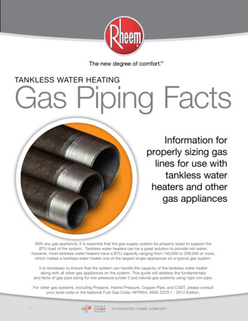
PressureSwitchCoverPlateCutSensorTubesBleed TubeBleed TubeOrificeCollectorPanFigure 10. Vent Collar Detail2.Remove the nut and restrictor plate from the ventcollar assembly and discard the restrictor plate.Select the appropriate dilution cover plate, as notedin vent kit #903196. Fit the clearance hole in thecover plate over the weld stud. The cover platemust cover the hole(s) on the vent collar assembly.Tighten the nut securely while holding the coverplate in position. (See Figure 10.)3.Bypass the vent switch by removing both wires fromthe vent switch and attaching them to the wire nut.(See Figure 11.)Figure 9. Bleed Tube InstallationThis vent pipe must be used for the entire length of the ventrun. The installation must be in accordance with allinstructions supplied by the vent manufacturer for use onCategory III appliances. When venting horizontal this isdefined as a Category III furnace, the vent pressure ispositive, and the venting system must be sealed in bothhorizontal and vertical runs.For horizontal venting installations the transition assemblymust be modified by adding a bleed tube to the pressureswitch tube and bypassing the vent switch. All modelfurnaces will require Vent Kit #903196 for horizontalventing.NOTE: No bleed tube is required for the model with the45,000 Btu/hr input rating.Horizontal Venting:1. Remove the rubber tubing from the pressure switchsensor tube and the collector pan sensor tube. Cut 1/2inch from one end of the rubber sensor tube, fold in halfand cut along the bend line. Discard the 1/2 inch longpiece of tubing. Select the correct bleed tube, using thetable provided with vent kit #903196, and place the othertwo pieces on both ends of the bleed tube. Do not coverthe hole in the bleed tube. Place the assembly back onthe pressure switch sensor tube and the collector pansensor tube. (See Figure 9.)! CAUTION:Do not drill holes through the vent pipe or fittingson a horizontal vented furnace. Do not use sheetmetal screws, or rivets. Drilling, screws, or rivetswill cause leaks.The components of the horizontal vent system must not bepenetrated, with screws, rivets, or other devices, eitherwhen joining pipes and fittings or using support straps. Alljoints must be sealed with high temperature siliconebefore locking bands are installed. If the lengths of pipemust be cut, the joint must still be sealed with silicone andthe locking band used. When installing the condensatetube
Horizontal Furnace Installation These furnaces can be installed horizontally in an attic, basement, crawl space or alcove. It can be suspended from a ceiling in a basement or utility room in either a right to left airflow or left to right airflow. (See Figures 2 and 3.) If the furnace is to be suspended from the ceiling, it will be