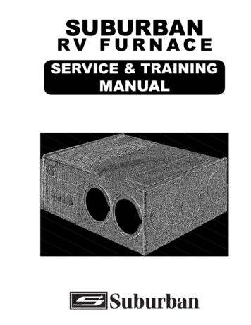
Transcription
676 Broadway StreetDayton, Tennessee 37321423-775-2131www.AIRXCEL.comINSTALLATION INSTRUCTIONSFOR MODEL P-40Design evaluated by CSA in accordance with Section 3280.707(a) (2) of HUD Manufactured Housing Constructionand Safety Standard for Energy Efficiency.This design is UL listed and meets UL 307B Standard for installation in recreational vehicles and mobile homes only.This design is also certified by the Canadian Standard Association for installation in recreational vehicles only. In orderfor the furnace to operate in conformity with generally accepted safety regulations, the installation instructions must befollowed. Failure to comply with the installation instructions will void the warranty on the furnace and any responsibilityon the part of AIRXCEL, INC. - SUBURBAN DIVISION.The furnace was inspected before it left the factory. If any parts are found to be damaged, do not install thefurnace. Immediately contact the transportation company and file a claim.This book contains instructions covering the operation and maintenance of your furnace. INSTALLER:LEAVE THIS MANUAL WITH THE APPLIANCE. CONSUMER: RETAIN THIS MANUAL FOR FUTUREREFERENCE. Should you require further information, contact your dealer or nearest Suburban ServiceCenter.WARNINGInstallation of this appliance must be made inaccordance with the written instructions providedin this manual. No agent, representative oremployee of Suburban or other person hasthe authority to change, modify or waive anyprovision of the instructions contained in thismanual.WARNINGFIRE, EXPLOSION ANDASPHYXIATION HAZARDImproper adjustment, alteration, service,maintenance or installation can cause seriousinjury or death.Read and follow instructions and precautionsin User’s Information Manual provided withthis furnace. Installation and service must beperformed by a qualified service agency or thegas supplier.WARNINGBe sure the furnace and all ignition systems are“OFF” during any type of refueling and whilevehicle is in motion or being towed.PN: 20557104-19-2018WARNINGFIRE OR EXPLOSION HAZARDFailure to follow safety warning exactlycould result in serious injury, death orproperty damage.— Do not store or use gasoline or otherflammable vapors and liquids in the vicinityof this or any other appliance.— WHAT TO DO IF YOU SMELL GAS Evacuate all persons from the vehicle. Shut off the gas supply at the gascontainer or source. Do not touch any electrical switch, oruse any phone or radio in the vehicle. Do not start the vehicle’s engine orelectric generator. Contact the nearest gas supplier orqualified service technician for repairs. If you cannot reach a gas supplier orqualified service technician, contactthe nearest fire department. Do not turn on the gas supply until thegas leak(s) has been repaired.— Installation and service must beperformed by a qualified installer, serviceagency or the gas supplier.
WARNINGCAUTIONDue to the differences in vinyl siding, this appliance should not be installedon vinyl siding without first consulting with the manufacturer of the sidingor cutting the siding away from the area around the appliance vent.CARBON-MONOXIDE POISONING HAZARDFailure to follow instructions could resultin severe personal injury or death due tocarbon-monoxide poisoning, if combustionproducts infiltrate into the building.In any installation in which the vent of this appliance can be covereddue to the construction of the RV or some special feature of the RVsuch as slide out, pop-up etc. always insure that the appliance cannotbe operated by setting the thermostat to the positive “OFF” position andshutting off all electrical and gas supply to the appliance. Never operatefurnace with vent covered.Check that all openings in the outside wallaround the vent (and air intake) pipe(s) aresealed to prevent infiltration of combustionproducts into the building.This furnace must be installed and vented as described in thismanual so that the negative pressure created by the air circulating(return air) fan cannot affect the combustion air intake or ventingof any other appliance. It is imperative that the products ofcombustion be properly vented to the atmosphere and that allcombustion air supplied to burner be drawn from the outsideatmosphere. (See Installing Vent Assembly.)Check the furnace vent (and air intake)terminal(s) are not obstructed in any wayduring all seasons.IMPORTANTFOR YOUR SAFETYIf this furnace is to be connected to a common duct system alsoserving a cooling unit, a manual or automatic damper is requiredto prevent any cold conditioned air from circulating back into thefurnace. Cold air passing over the furnace combustion chamberduring the operation of the cooling unit can result in the formationof condensation inside the furnace combustion chamber. Thiscondensation may promote corrosion and premature failure ofthe combustion chamber.DO NOT STORE OR USE GASOLINE OROTHER FLAMMABLE VAPORS AND LIQUIDSIN THE VICINITY OF THIS OR ANY OTHERAPPLIANCE.WARNINGNOTE: These furnaces shall be installed so the electrical components are protectedfrom water.Improper installation, adjustment, alteration,service or maintenance can cause propertydamage, personal injury or loss of life. Referto the installation instructions and/or ownersmanual provided with this appliance. Installationand service must be performed by a qualifiedinstaller, service agency or the gas supplier.NOTE: Do not install the furnace with the vent facing toward the forward end ofthe coach. See figures 8 and 9.Please adhere strictly to the installation instructions to insure properinstallation and safe operation, as well as adequate clearances for accessibility.This furnace is design certified for use with propane or conversion to natural gas.Gas supply pressure for purposes of input UMPropane11.0” W.C.*13.0” W.C.*Natural Gas5.0” W.C.*7.0” W.C.**Water columnIn the U.S.A., the installation of the furnace must be in accordance with local codesand regulations. In the absence of local codes and regulations, installation mustcomply with the latest edition of:1.Standard for Recreational Vehicles NFPA 1192.2.National Fuel Gas Code ANSI Z223.1/NFPA 54.3.Furnace must be electrically grounded in accordance with the latest edition ofthe National Electrical Code NFPA 70.This unit is equipped with an electric igniter device that has an energy consumptionof .1 amp @24 volts A.C.WARNINGInstallation of this appliance must be made inaccordance with the written instructions providedin this manual. No agent, representative oremployee of Suburban or other person hasthe authority to change, modify or waive anyprovision of the instructions contained in thismanual.In Canada, the furnace must be installed in accordance with:1.Standard CAN/CSA Z240.0.2-08 Recreational Vehicles.2.CSA Standard CAN/CSA Z240.6.2-08/C22.2 No. 148-08 ElectricalRequirements for Recreational Vehicles.3.Standard CAN/CSA Z240.4.2-08 Installation Requirements for PropaneAppliances and Equipment in Recreational Vehicles.4.CAN/CGA B149 Installation Codes.5.Any applicable local codes and regulations.CAUTIONRETURN AIRNOTE: Return air must be from within the living area of the coach.NOTE: RV’s that have a wall of separation to a cargo area (Toy Box) to transportinternal combustion engine vehicles must not have return air opening from this area.There are three methods described below for installing the furnace. Regardless ofthe method you choose, we require that a permanent opening be provided in theinterior cabinetry of the coach directly in front of the furnace. The opening must allowfor free, unobstructed removal of the furnace. This opening may be used as a meansof providing circulating return air to the furnace. It is recommended that the openingtotal 64 square inches. Suburban also recommends a return air opening of 49 squareinches be provided in the left side of coach cabinetry and centered by room air bloweropening. (See Figure 3.) These are suggested locations for return air. Other locationsand areas may be used. Regardless of the location for return air, the return air to thefurnace must total 113 square inches. (See Figure 3.)If possible, do not install the furnace to where the vent can be covered orobstructed when any door on the trailer is opened. If this is not possible,then the travel of the door must be restricted in order to provide a 6”minimum clearance between the furnace vent and any door wheneverthe door is opened.NOTE: The exhaust temperature of this furnace could discolor or warp somematerials. You should verify that the material used on the coach door, panel, or coverwill not discolor or warp from the exhaust temperature whenever any door, panel, orcover is in the open position.2It is important that adequate return air be provided to assure normal heating andoperation of the furnace. Failure to provide the minimum return air opening as wellas an adequate opening for furnace removal, voids the warranty.
A.INSTALLATION DIRECTLY AGAINST OUTER SKIN OF COACH(See Figure 1)EXTENSION TUBEKIT NUMBERMIN./MAX. LENGTH(EXTENSION TUBE RANGE)MAXIMUM WALL THICKNESS FOR THIS TYPE INSTALLATION IS 2 1/4”5209742-1/4” to 3-1/8”Locate the furnace near lengthwise center of the coach. Do not install thefurnace with the vent facing toward the forward end of the coach.2.Choose a location for installation out of the way of wires, pipes, etc. whichmight interfere with the installation. Adhere to the minimum clearances fromthe cabinet to combustible constructions listed in Table 1. Refer to Figure 3 forillustration of furnace clearances.NOTE: Side and top clearances may be 0” for through the wall installations up to amaximum wall thickness of 2 1/4”. (See Figure 1.)3.When an appliance is installed directly on carpeting, tile or other combustiblematerial, other than wood flooring, the appliance shall be installed on a metal orwood panel extending the full width and depth of the appliance. If preferred, thecarpeting, tile or combustible materials, other than wood may be cut away thefull length and depth of the appliance plus the appliance minimum clearancesto combustibles. (See Table 1.)4.Cut an opening through the inner wall 12 7/16 x 13 1/8”. This will allow the rearof the furnace to be installed against the outer skin of the coach. (See Figure 1.)5.Cut two 3” diameter holes through the outer skin of coach as shown in Figure 1.6.Put furnace in place, making sure that rear of furnace cabinet is as close toouter skin of coach as possible and still assure proper vent tube overlap. (SeeInstalling Vent Assembly).7.Secure furnace to the floor using the two (2) holes provided in furnace cabinet.(See Figure 1.)8.Install vent assembly. (See instructions for installing vent.)5209753-1/8” to 4-7/8”5205954-7/8” to 7”5205967” to ust andIntake TubeP-401”2”2”1”0”0”3/8”TABLE 2INSTALLING VENT ASSEMBLYThe vent outlet must be installed so it is in the same atmospheric pressure zone asthe combustion air intake. The exhaust and intake tubes must be installed from theoutside, pass through the RV skin and slide onto the furnace exhaust and intake.WARNINGDo not alter the vent assembly supplied withthis furnace. Any modifications will result inimproper installation which could cause unsafefurnace operation.CAUTIONCombustion air must not be drawn from the living area. All air forcombustion must be drawn from the outside atmosphere. All exhaustgases must be vented to the outside atmosphere - never inside the RV.Therefore, it is essential to insure that the vent cap and tube assembliesare properly installed.- NOTE - 0” MEANS TO SPACER BUMPSCLEARANCE FROM DUCTS TO COMBUSTIBLE MATERIAL WITHINFIRST 3 FEET FROM FURNACE - 1/4” (See Figure 3)1.TABLE 1B.INSTALLATION DIRECTLY AGAINST INNER WALL OF COACH(See Figure 2)2.3.MAXIMUM WALL THICKNESS FOR THIS TYPE INSTALLATION IS 2 1/4”1.2.3.4.5.6.7.Locate the furnace near lengthwise center of the coach. Do not install thefurnace with the vent facing toward the forward end of the coach.Choose a location for installation out of the way of wires, pipes, etc. whichmight interfere with the installation. Adhere to the minimum clearances fromthe cabinet to combustible construction as listed in Table 1. Refer to Figure 3for illustration of furnace clearances.When an appliance is installed directly on carpeting, tile or other combustiblematerial, other than wood flooring, the appliance shall be installed on a metal orwood panel extending the full width and depth of the appliance. If preferred, thecarpeting, tile or combustible materials, other than wood may be cut away thefull length and depth of the appliance plus the appliance minimum clearancesto combustibles. (See Table 1.)Locate center lines for exhaust and intake tubes as shown in Figure 2. Cut two3” diameter holes through coach wall for exhaust and intake. (See Figure 2.)Put furnace in place, making sure that rear of furnace cabinet is as close toinner wall of coach as possible and still assure proper vent tube overlap. (SeeInstalling Vent Assembly).Secure furnace to the floor using the two (2) holes provided in the furnacecabinet. (See Figure 1.)Install vent assembly. (See instructions for installing vent.)4.Apply caulking to RV skin behind vent cap as shown in Figure 2. Apply caulkinggenerously around perimeter of vent cap and across center as shown.Insert intake tube through RV skin and slide it onto the furnace intake (SeeFigure 2.) Minimum tube overlap of 1/2” is required.Insert the vent cap assembly with heat shield collar through the 3” diameterhole in the RV skin as illustrated in Figure 2. Slide vent cap exhaust tube ontofurnace exhaust. Minimum tube overlap of 1 1/4” is required.Attach vent cap assembly to outer skin of RV with the six (6) screws provided.Do not install vent assembly upside down. The word “Suburban” must be rightside up.CONNECTING GAS SUPPLYConnect the gas supply to the furnace at the manifold. A suggested method isillustrated in Figure 1. Other methods are acceptable if they allow for the gas to beshut off at the furnace for furnace removal while allowing other appliances to remainoperational.NOTE: The compound used on threaded joints must be resistant to propane andnatural gas.NOTE: The appliance and its individual shut-off valve must be disconnected from thegas supply piping system during any pressure testing of that system at test pressurein access of 1/2 PSIG.The appliance must be isolated from the gas supply piping by closing its individualmanual shut-off valve during any pressure testing of the gas supply piping system attest pressure equal to, or less than, 1/2 PSIG.1.C. INSTALLATION USING VENT EXTENSION TUBESWhen it is not possible to install the furnace as described in installations A or B,extension tubes must be used to extend the exhaust and intake tube to the vent tubeassemblies on the outside of the coach. Avoid the use of extension tubes wheneverpossible. If they must be used, it is important that the correct length tubes are used.2.3.In order to determine the correct extension tube kit, you must determine the range inwhich the extension falls. To do this, determine where the furnace is to be installedand measure the distance from the end of the exhaust and intake tube to the outeredge of the coach skin. This determines the extension tube range you need. Table 2lists by kit number the vent extension range up to 9”.4.Be sure that the manual shut-off valve is outside of the furnace jacket andeasily accessible. (See Figure 1.)A drip leg should be installed upstream of the manual shut-off valve exterior tounit casing.In order to maintain a check on gas supplied pressure to the furnace, Suburbanadvises the installer to provide a 1/8” NPT plug tap for test gauge connectionimmediately upstream of the gas supply connection to the furnace and that itbe readily accessible.After the furnace has been connected to the gas supply, all joints must bechecked for leaks.WARNINGExample: If the distance you measured is 2 7/8”, using Table 2 as your guide, you willorder Kit #520974 which accommodates a range from 2 1/4” to 3 1/8”. The extensiontube kit comes with complete installation instructions.Never check for leaks with an open flame. Turnon the gas and apply soapy water to all joints tosee if bubbles are formed.WARNINGUnder no circumstances are the extensiontubes, as supplied by Suburban, to be cut,altered, or modified in any way. To do so couldbe dangerous and will void the responsibility ofAIRXCEL, INC. - SUBURBAN DIVISION.CONNECTING ELECTRICAL SUPPLYThis furnace is wired for 120 volts A.C. only. Connect the 120 volts A.C. wire leads inthe junction box located on the right side of the furnace cabinet.All wiring and wire connections must conform to local codes and the latest edition ofthe National Electrical Code NFPA 70.3
CONNECTING DUCTS TO FURNACE3.The following duct requirements must be followed in order to assure proper operationof the furnace:1.Maintain a minimum of 48 square inches open duct area throughout entire ductsystem including through register. (Minimum 4 ducts 4” diameter.) Applicableto under floor ducting as well.NOTE: Ducts terminating in a dead air space (like holding tank compartmentsor cargo areas (Toy Boxes) with no means for return air recirculation shouldnot be counted in the required duct area. Also, ducts 2” in diameter or smallershould not be counted in the required duct area.No outlet register is to be placed within 18” of the return air opening. Any2.register installed at 18” should never be adjusted to blow the outlet air towardthe return air opening. If a register is installed on a wall 90 degrees to thereturn air, it can be less than 18”.3.Make the duct connections at the furnace cabinet tight. Loose connections willresult in overheating of the component parts on the furnace and a reduction ofthe heated air flow through the duct system.4.Avoid making any sharp turns in the duct system. Sharp turns will increase thestatic pressure in the plenum area and could cause the furnace to cycle.5.Avoid making a lot of turns in the duct system. The straighter the duct system,the better the performance of the furnace.6.Maintain a minimum of 1/4” clearance where ducts pass through anycombustible construction; such as, coach cabinetry. (See Figure 3.)NOTE: UL listed duct materials can be “0” clearance.7.Do not install air boosters in the duct system. Such devices will cause thefurnace to cycle on limit and cause erratic sail switch operation.NOTE: After installation of the furnace and duct system is completed, adjustments mustbe made to obtain a temperature rise within the range specified on the Rating Plate.4.5.6.7.You, as the owner/user, should inspect the furnace monthly during theheating season for presence of soot on vent. Operating the furnace under thiscondition could lead to serious property damage, personal injury or loss of life.If soot is observed on the vent, immediately shut the furnace down and contacta qualified service agency.Listed below are several safety related items that you should follow during theheating season to assure continued safe operation of the furnace.1.Inspect furnace venting. Venting must be free of obstructions, void of soot, andproperly terminated to the atmosphere. (See Installing Vent Assembly.)WARNINGDo not install screens over the vent for anyreason. Screens will become restricted andcause unsafe furnace operation. Accessoriesare being marketed for RV products which wedo not recommend. For your safety, only factoryauthorized parts are to be used on your furnace.INSTALLING THERMOSTATThe thermostat used with this unit must have NO voltage output to return leg whenthere is not a call for heat or in the “OFF” setting.Locate the room thermostat approximately 4-1/2 feet above the floor on an insidebulkhead where it is not affected by heat from any source except room air. Connectthermostat wiring to wires on right side of furnace marked “Thermostat Wires”. Whitewire with red stripe is power wire to thermostat. (See wiring diagram.)If your furnace is equipped with a thermostat that has an adjustable anticipator,the anticipator should be set at .7 amps. If you desire linger heating cycles, adjustthe anticipator to a higher setting. If you desire shorter heating cycles, adjust theanticipator to a lower setting. Adjustments to the anticipator setting should be madein .5 amp increments.2.Periodically inspect the vent for obstructions or presence of soot. Soot isformed whenever combustion is incomplete. This is your visual warning thatthe furnace is operating in an unsafe manner. If soot is present, immediatelyshut furnace down and contact your dealer or a qualified service person.3.Periodically observe the main burner flame to assure it is burning with a hardblue flame with well defined burner ports (See Figure 6). If flame appearsyellow or burner has a lazy flame, shut furnace down. It is possible that burnerneeds cleaning or replaced. To inspect the main burner, remove the four (4)screws (A, B, C and D) securing the burner access door to the combustionchamber (See Figure 5). If excessive rust and corrosion are present on burnersurface, the burner must be thoroughly cleaned or replaced. The burner maybe cleaned using a steel wire brush and blown clean using high compressionair. Contact a qualified service person for assistance.NOTE: To observe flame, cabinet front must be removed. Operation of burner canthen be observed through the viewing window on front of chamber (See Figure 5).4.Keep furnace clean. More frequent cleaning may be required due to excessivelint from carpeting, bedding material, etc. It is imperative that controlcompartments, burners and circulating air passageways of the appliance bekept clean.5.The motor is permanently lubricated and requires no oiling.6.Keep the furnace area clear of any combustible materials, gasoline or otherflammable vapor and liquids.7.Before operating furnace, check the location of the furnace vent to make sure itwill not be blocked by the opening of any door on the trailer. If it can be blocked,do not operate the furnace with the door open.8.Do not restrict the flow of combustion air or the warm air circulation to thefurnace. To do so could cause personal injury and/or death.9.Never operate the furnace if you smell gas. Do not assume that the smellof gas in your RV is normal. Any time you detect the odor of gas, it is tobeconsidered life threatening and corrected immediately. Extinguish any openflames including cigarettes and evacuate all persons from the vehicle. Shutoff gas supply at Propane gas bottle. (See safety notice on front cover of thismanual.)10. Immediately shut furnace down and call a service agency if furnace cycleserratically or delays on ignition.PREVENTIVE MAINTENANCEWARNINGIf the user of this appliance fails to maintain it inthe condition in which it was shipped from thefactory or if the appliance is not used solely for itsintended purpose or if appliance is not maintainedin accordance with the instructions in this manual,then the risk of a fire and/or the production ofcarbon monoxide exists which can cause personalinjury, property damage or loss of life.CAUTIONLabel all wires prior to disconnecting for servicing and servicing controls.Wiring errors can cause improper and dangerous furnace operation. Properpolarity MUST BE OBSERVED so the furnace motor will run with the properdirection of rotation to insure correct air delivery. (See wiring diagram).Always verify proper operation of furnace after servicing.Your furnace should be inspected by a qualified service agency yearly before turningthe furnace on. Particular attention should be given to the following items.1.Inspect furnace installation and vent termination to be sure furnace is properlysecured in place (see Installation Instructions), that vent terminates to theatmosphere, and that vent tubes overlap properly (see Installing Vent Assembly.)2.Inspect chamber and venting to assure that these components are physicallysound without holes or excessive corrosion and that the installation and/or re-installation is in accordance with Suburban’s installation instructions.(Reference installation manual supplied with furnace.)WARNINGShould overheating occur, or the gas supplyfail to shut off, shut off the manual gas valve tothe appliance before shutting off the electricalsupply.WARNINGIt is imperative that the products of combustionbe properly vented to atmosphere and that allcombustion air supplied to burner be drawnfrom outside atmosphere.Check the base on which furnace is mounted. Be sure it is physically sound,void of any sagging, deterioration, etc.Inspect furnace, the venting, ducting and gas piping to furnace for obvioussigns of deterioration. Correct any defects at once.Inspect combustion chamber for restrictions in exhaust or intake. It is imperativethat the flow of intake combustion air and the flow of exhaust gases beingexpelled to the outside atmosphere not be obstructed. Any soot or loose debrisshould be blown out using compressed air. (See Figure 7.)Inspect all gaskets. If any gaskets show signs of leakage or deterioration, replacethem. Safe operation of the furnace depends on all gaskets being tight.Inspect return air inlet openings to the furnace. Remove any restrictions toassure adequate air flow.11.12.13.14.4Never attempt to repair damaged parts. Always have them replaced by aqualified service agency.Never attempt to repair the furnace yourself. Seek the help of a qualifiedservice person.Never restrict the ducting installed by your trailer manufacturer. To do so couldcause improper furnace operation.Do not install air boosters in the duct system. Such devices will cause thefurnace to cycle on limit and to have erratic sail switch operation.
15.16.17.18.19.TO SHUT DOWNClothing or other flammable material should not be placed on or near theappliance.Always follow the Operating Instructions. Do not deviate from the step-by-stepprocedures.Do not use this appliance if any part has been submerged under water.Immediately call a qualified service technician to inspect the appliance andto replace any part of the control system and any gas control that has beensubmerged under water.When considering add-on rooms, porch or patio, attention must be given to theventing of your furnace. For your safety, do not terminate furnace vent insideadd-on rooms, screen porch or onto patios. Doing so will result in products ofcombustion being vented into the room or occupied areas.In any installation in which the vent of this appliance can be covered due tothe construction of the RV or some special feature of the RV such as slide out,pop-up etc. always insure that the appliance cannot be operated by setting thethermostat to the positive “OFF” position and shutting off all electrical and gassupply to the appliance. Never operate furnace with vent covered.Set the thermostat to lowest setting, then move lever to “OFF” position.Turn off all electric power to the appliance if service is to be performed.Turn shut off valve clockwise to “OFF”. Do not force.1.2.3.CONVERTING FROM PROPANETO NATURAL GASThe furnace was factory equipped for use with Propane gas. For natural gas, use theNo. 30 drill orifice provided with the furnace. (Orifice is attached to furnace manifoldnear valve.)Gas supply (line pressure) for natural gas should be:GASNatural GasMINIMUMMAXIMUM5.0” W.C.*7.0” W.C.**Water columnOPERATING INSTRUCTIONSCONVERTING FURNACE TO NATURAL GASWARNINGShut off gas supply.Disconnect gas supply and electrical power.Remove outside vent assembly.Remove chamber assembly from cabinet.Remove manifold assembly.Remove orifice from manifold assembly.Install the natural gas orifice (No. 30 drill) supplied.Convert valve to natural gas by removing regulator stem, turning over andreinstalling. (Ring on stem will now show natural).Reinstall manifold assembly.Slide chamber assembly into cabinet and secure.Reconnect vent assembly.Reconnect gas and electrical connections.Perform operations check and inspect for gas leaks.1.2.3.4.5.6.7.8.Do not operate furnace while vehicle is in motionor being towed.NOTE: During initial firing of this furnace a burn-off of excess paint and oils remainingfrom manufacturing process may cause “smoking” for 5 - 10 minutes.1.Stop! Read Users Information Manual supplied with furnace.2.Turn the manual valve or the valve at the outside Propane tank to the “OFF”position. Do not force.Set thermostat above room temperature to begin blower operation. A slight3.delay will occur before the blower comes on. Allow blower to run for 5 minutesfor combustion chamber purge cycle. If blower does not come on or stopsbefore ignition cycle, go to shut down and contact your dealer or a localrecreational vehicle service agency.After 5 minutes, move thermostat lever below room temperature. Blower will4.remain on. Wait approximately 2 minutes for blower to go off.5.Open manual shut-off valve or the valve at the outside Propane tank. Correctoperating characteristics depend on the valve being positioned fully open.Never attempt to operate with a valve partially closed.Set thermostat lever to desired setting. If set above room temperature, blower6.will come on.7.Allow 30 seconds for main burner to light after blower comes on. This furnaceis equipped with an ignition device which automatically lights the burner. Do nottry to light the burner by hand.If burner does not light, repeat Steps 1 through 8.8.9.If after three (3) attempts with no ignition, go to shut down and contact yourdealer or a local recreational vehicle service agency. Do not continue to cyclefurnace through thermostat in an attempt to get ignition.9.10.11.12.13.NOTE: After completing the conversion, check the manifold (gas) pressure at thepressure tap located on the outlet side of valve. Pressure should be 3.2” W.CPARTS AND SERVICEContact a conveniently located recommended Suburban Service Center. Describeto
A. INSTALLATION DIRECTLY AGAINST OUTER SKIN OF COACH (See Figure 1) MAXIMUM WALL THICKNESS FOR THIS TYPE INSTALLATION IS 2 1/4" 1. Locate the furnace near lengthwise center of the coach. Do not install the furnace with the vent facing toward the forward end of the coach. 2. Choose a location for installation out of the way of wires, pipes .