Transcription
SUBURBAN MANUFACTURING COMPANY676 Broadway StreetDayton, Tennessee 37321423-775-2131www.RVComfort.comINSTALLATION MANUALFor Furnace ModelsNT-16SEQ NT-20SEQThe design of these furnaces have been certified for installation in recreational vehicles only. In order for these furnaces to operate in conformitywith generally accepted safety regulations, the installation instructions outlined in this book must be followed. Failure to comply with the installationinstructions will void any responsibility of Suburban Manufacturing Company. Your furnace was inspected before it left the factory. If any parts arefound to be damaged, do not install the furnace. Any damages should be reported to the transportation company immediately and the appropriateclaims filed.WARNING! Improper installation, adjustment, alteration, service or maintenance can causeproperty damage, personal injury or loss of life. Refer to the installation instructions and/or owners manual provided with this appliance.INSTALLATION INSTRUCTIONSWARNING! Installation of this appliance must be made in accordance withthe written instructions provided in this manual. No agent, representativeor employee of Suburban or other person has the authority to change,modify or waive any provision of the instructions contained in thismanual.CAUTION: If possible, do not install the furnace to where the vent can becovered or obstructed when any door on the trailer is opened. If this is notpossible, then the travel of the door must be restricted in order to providea 6” minimum clearance between the furnace vent and any door wheneverthe door is open.NOTE: The exhaust temperature of this furnace could discolor or warp somematerials. You should verify that the material used on the coach door, panel, orcover will not discolor or warp from the exhaust temperature whenever any door,panel, or cover is in the open position.In the USA, the installation must conform with local building codes. In the absenceof local building codes, refer to the latest edition of:1-Standard for Recreational Vehicles NFPA 1192.2-National Fuel Code ANSI Z223.1/NFPA 54.3-The furnace must be electrically grounded in accordance with the latestedition of the National Electrical Code NFPA 70.4-The installation of the furnace shall be in accordance with any applicablelocal codes and regulations.In Canada, the furnace must be installed in accordance with:1-Standard CAN/CSA Z240.0.2-08 Recreational Vehicles2-CSA Standard CAN/CSA Z240.6.2-08/C22.2Requirements for Recreational Vehicles.No.148-08ElectricalCAUTION: Due to the differences in vinyl siding, this appliance should notbe installed on vinyl siding without first consulting with the manufacturerof the siding or cutting the siding away from the area around the appliancevent.3-Standard CAN/CSA Z240.4.2-08 Installation Requirements for PropaneAppliances and Equipment in Recreational Vehicles.CAUTION: In any installation that has the exhaust/intake vent covered or theminimum clearances to the room air grill reduced by some special featureof the RV such as a slide-out, pop-up, etc. in the travel or storage mode, aswitch must be installed to insure unit is inoperable in this mode.5-Any applicable local codes and regulations.NOTE: These furnaces must be installed and vented as described in this manualso that the negative pressure created by the air circulating (return air) fan cannotaffect the combustion air intake or venting of any other appliance. It is imperativethat the products of combustion be properly vented to the atmosphere and that allcombustion air supplied to burner be drawn from the outside atmosphere. (See“Installing Vent Assembly”.)NOTE: These furnaces shall be installed so the electrical components areprotected from water.These furnaces will accommodate an installation depth from 21” to 27 3/4”,depending on the intake vent tube length you select. (See Figure 1.)Please adhere strictly to the following instructions to insure proper installation andsafe operation, as well as adequate clearances for accessibility.The efficiency rating of the appliance is a product thermal efficiency ratingdetermined under continuous operating conditions and was determinedindependently of any installed system.These furnaces are certified for use with propane/LP gas only. Gas supplypressure for purposes of input adjustment:GasPropane/LP*Water columnPart Number 2048778-1-20114-CAN/CGA-B149 Installation CodesThe furnace cabinet must extend through the coach cabinetry 1 3/8” as shown inFigure 1. The 1 3/8” extension must be held in order to assure that the front grille willproperly attach to the furnace cabinet. Adequate clearances must be maintainedaround furnace cabinet so that the unit will be accessible for servicing.TO INSTALL THE FURNACE1. Locate the furnace near lengthwise center of the coach. Do not install thefurnace with the vent facing toward the forward end of the coach.2. Select a location for installation out of the way of wires, pipes, etc. that mightinterfere with installation. Adhere to the following minimum clearances from thefurnace cabinet to combustible construction.Back - 0”Floor - 0”Top - 5/8”Sides - 5/8”NOTE: Side and top clearances of furnace cabinet may be 0” for through the wallinstallations up to a maximum of 2 1/2” wall thickness (See Figure 2.)The following minimum clearances from the warm air discharge grille tocombustible materials must be maintained: See Figure 10 for 0” clearance ofgrille if framed.Models NT-16SEQ, NT-20SEQMinimumMaximumFront 24”11” W.C.*13” W.C.*Left Side 1” Right Side 8”Top 1”Floor 1/4”orLeft Side 8” Right Side 1”(See Figure 8)
CONNECTING ELECTRICAL SUPPLYReduced Front ClearanceFront 12” NT-16SEQTop 1”Front 18” NT-20SEQSide 0”*CAUTION: These furnaces are designed for a negative ground 12 voltD.C. system only. Do not attempt to alter the furnace for a positive groundsystem or connect the furnace directly to 115 volts A.C. Damage to furnacecomponent parts will occur. Connect only to a protected circuit fused fornot more than 7.5 amps.Floor 1/4”Note: Must provide an additional 12 sq. in. of return air when side clearanceis 1” - 8”(See Figure 9)Be sure all wiring to the furnace is of heavy enough gauge to keep the voltagedrop through it to a minimum and to provide enough power for start-up surge. No.12 gauge wire is recommended.3. When an appliance is installed directly on carpeting, tile, or other combustiblematerial other than wood flooring, the appliance shall be installed on a metal orwood panel extending the full width and depth of the appliance. If preferred, thecarpeting, tile or combustible materials, other than wood may be cut away thefull length and depth of the appliance plus the appliance minimum clearances tocombustibles.If any of the original wire that is supplied with the appliance must be replaced, itmust be replaced with Type 105 C or its equivalent.Connect the power supply to the red and yellow wires on the right side of thefurnace. The wires are color coded, red for positive ( ) and yellow for negative(-). This polarity must be observed so the furnace motor will run with the properdirection of rotation to insure correct air delivery. (See wiring diagram.)4. Cut or frame an opening in the coach cabinetry 10 9/16” x 10 3/16” as shown inFigure 2 or Figure 3.If the furnace power supply is to be from a convertor, we recommend that theconvertor system used to power the furnace be wired in parallel with the battery.This will serve two purposes:5. Slide the front of the furnace through the opening and extend it beyond thecoach cabinetry 1 3/8” as shown in Figure 2 or Figure 3.6. Determine “X” dimension as shown in Figure 1.1. Provide a constant voltage supply to the furnace.7. Determine “Y” dimension as shown in Figure 1.2. Filter any A.C. spikes or volt surges.8. If X - Y is less than 21”, then an opening 9 5/8” x 9 3/8” must be cut through theinner wall only. DO NOT CUT THROUGH COACH SKIN. (See Figure 2.) Next,locate the center line of the exhaust and intake tube. Cut two 2 1/4” diameter holesthrough the outer skin as shown in Figure 4.NOTE: Furnace models NT-16SEQ AND NT-20SEQ are equipped with an electricignitor device that has an energy consumption of.1 amps at 12 volts D.C.CONNECTING THERMOSTATThe thermostat used with this unit must have NO voltage output to return leg whenthere is not a call for heat or in the “OFF” setting.NOTE: Whenever the furnace cabinet is installed through the outside wall, thereturn air louvers on the furnace cabinet must not be blocked. The maximumprojection of the furnace cabinet into the wall is 2 1/2”. (See Figure 2.)Locate the room thermostat approximately 4 1/2 feet above the floor on an insidebulkhead where it is not affected by heat from any source except room air.NOTE: Furnace cabinet approved for 0” clearance to combustible materials rear2 1/2” of furnace cabinet.9. If X - Y is 21” or greater, two methods may be used to install the furnace.Connect the thermostat wires to the blue wires on the right side of the furnace.(See wiring diagram.) If your furnace is equipped with a thermostat that hasan adjustable anticipator, the anticipator should be set at .7 amps. If you desirelonger heating cycles, adjust the anticipator to a higher setting. If you desireshorter heating cycles, adjust the anticipator to a lower setting. Adjustments to theanticipator setting should be made in .5 amp increments.a. Cut a 4” x 7 1/2” opening through combustible wall as shown inFigure 3. DO NOT CUT THROUGH TRAILER SKIN. Next, locate the center lineof the exhaust and intake tube. Cut two 2 1/4” diameter holes through trailer skin.(See Figure 4.)b. If you do not wish to cut the 4” x 7 1/2” opening, locate the center lineof the exhaust and intake tube as shown in Figure 4. Next, cut two 2 3/4” diameterholes through trailer skin and also the combustible wall of the trailer as illustratedin Figure 6. Care must be taken when locating the center line of the exhaust andintake tube as well as when cutting the holes in order to assure a 3/8” clearancearound the exhaust and intake tube to combustible materials.INSTALLING VENT ASSEMBLYThe vent outlet must be installed so it is in the same atmospheric pressure zoneas the combustion air intake. The exhaust and intake tubes must be installedfrom the outside, pass through the RV skin and slide onto the furnace exhaustand intake.10. Refer to the chart in Figure 1 and select the range for which the ‘X’ dimensionfalls. The intake tube length directly to the left of the selected range is the lengthrequired. NOTE: The 7 3/4” length exhaust tube assembly will accommodate allapproved installation depths - only the intake tube must be ordered when needed.Under no circumstances should the standard 5” intake tube be cut or altered toadapt to the 21” - 23 1/4” range.WARNING! Do not alter the vent assembly supplied with this furnace.Any modifications will result in improper installation which could causeunsafe furnace operation. Never operate furnace with vent covered.CAUTION! Combustion air must not be drawn from the living area. All air forcombustion must be drawn from the outside atmosphere. All exhaust gasesmust be vented to the outside atmosphere - never inside the RV. Therefore,it is essential to insure that the vent cap and tube assemblies are properlyinstalled.11. Secure furnace to the floor using the two holes provided in furnace cabinet.(See Figure 2 or Figure 3.)12. NOTE: OPTIONAL DISCHARGE DUCT ADAPTER -The cabinet has a 4”diameter knockout on the left side of cabinet. (See Figure 6A.) A 4” diameterconnector can be attached to this location to provide a warm air discharge duct.(Not to exceed 10” in length.)1. Apply caulking to RV skin behind vent cap as shown in Figure 6. Apply caulkinggenerously around perimeter of vent cap and across center as shown.2. Insert intake tube through RV skin and slide it onto the furnace intake (SeeFigure 1.) Minimum tube overlap of 1/2” is required.CONNECTING GAS SUPPLYA 3/8” flare connection is provided on the right side of the furnace for the gas supplyconnection to the furnace.3. Insert vent cap exhaust tube through RV skin and slide it onto the furnaceexhaust (See Figure 1.) Minimum tube overlap of 1 1/4” is required.Connect the gas supply to the furnace at the manifold, following the suggestionsoutlined below. It will be necessary to hold the flare fitting on the furnace manifoldwhen connecting or loosening gas lines.4. Attach vent cap assembly to outer skin of RV with the six (6) screws provided.Do not install vent assembly upside down. The word “Suburban” must be rightside up.NOTE: Be sure all male joints have been treated with a sealing compoundresistant to the action of liquefied petroleum (LP) gas.In order to maintain a check on gas supply pressure to the furnace. Suburbanadvises the installer to provide a 1/8” NPT plug tap for test gauge connectionimmediately upstream of the gas supply connection to the furnace.NOTE: The appliance must be disconnected from the gas supply piping systemduring any pressure testing of that system at test pressure in excess of 1/2 PSIG.The appliance must be isolated from the gas supply piping during any pressuretesting of the gas supply piping system at test pressure equal to or less than 1/2 PSIG.WARNING! All joints must be checked for leaks. Do not use open flame tocheck for leaks! Use a soap and water solution.2
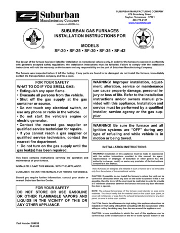
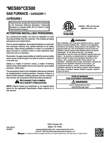
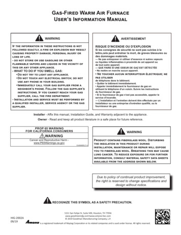
VENT TUBE INSTALLATIONDue to high temperatures, the unit should be located out of traffic andaway from furniture and draperies."X"Children and adults should be alerted to the hazards of high surfacetemperatures and should stay away to avoid burns or clothing ignition.Y"1 3/8"TRAILOR SKINVENT TUBE (EXHAUST) 8" X 2" O.D.Young children should be carefully supervised when they are in the sameroom as the unit.VENT CAP2 1/4"DIA.VENT TUBE (INTAKE) SEE CHART1 1/4" MIN. OVERLAPON EXHAUST7 1/2"Clothing or other flammable material should not be placed on or nearthe unit.Any safety screen or guard removed for servicing the unit must bereplaced prior to operating the unit.2 1/4"DIA.The area around the unit must be kept clear from combustible materials,gasoline and other flammable vapors and liquids.Installation and repairs should be done by a qualified service person. Theunit should be inspected before use and at least annually by a qualifiedservice person. More frequent cleaning may be required due to excessivelint from carpeting, bedding material, etc. It is imperative that controlcompartments, burners, and circulating air passageways of the unit bekept clean.MOUNTING SURFACE1/2" MIN. OVERLAPOF INTAKE TUBE21"PART NO. INTAKE TUBE LENGTH ONLY "X" DIMENSIONX0507112" O.D. X 2 3/4" SPECIAL21" TO 23 1/4"X0507122" O.D. X 5" *STANDARD23 1/4" TO 25 1/2"X0507082' O.D. X 7 1/4" SPECIAL25 1/2" TO 27 3/4"STANDARD TUBE FURNISHED WITH FURNACE.THE SPECIAL TUBES, IF NEEDED, MUSTBE ORDERED.NEVER INSTALL VENT TUBESWITH LESS THAN 1/2" OVERLAPON INTAKE & 1 1/4" ON EXHAUSTFigure 1BACK OF FURNACE CABINETTRAILER SKINPOWER SUPPLY & THERMOSTAT WIRESGAS INLET FOR ELECTRIC IGNITION MODELSSECURE UNIT IN PLACEWITH (2) SCREWSFigure 22 1/4" DIA. TWO HOLES THROUGH TRAILERSKINTRAILER SKINMOUNTING SURFACEINSIDE WALLPOWER SUPPLY & THERMOSTAT WIRESGAS INLET FOR ELECTRIC IGNITION MODELSSECURE UNIT IN PLACEWITH (2) SCREWS3Figure 3
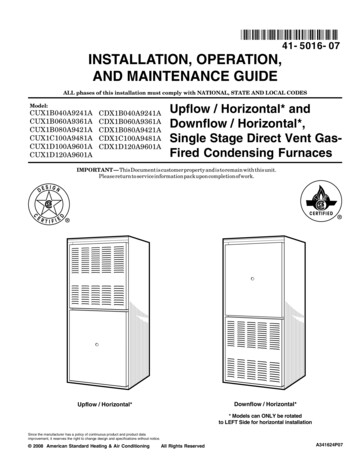
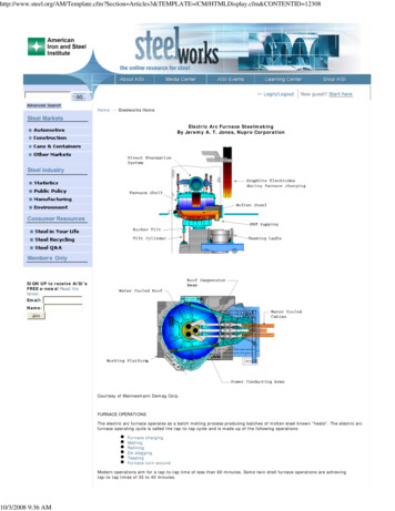
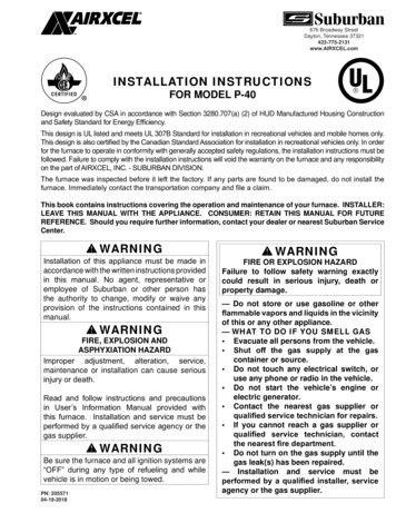
VENT CAP OUTLINE1347/64 DIA.(4) HOLES315169516132161691323216591614122FURNACE CABINETMOUNTING SURFACE2 1/4 DIA. (2) HOLESTHRU TRAILOR SKINBACK VIEW OF FURNACEFigure 4IMPORTANT:VENT CAP AND TUBE ASSY.MUST BE INSTALLED FROMOUTSIDE OF COACH.TRAILER SKINOUTLINE OF FURNACEHOLE DIA. IN OUTER SKIN MAY BE 2 1/4"IF OPENING CUT IN COMBUSTIBLE WALLIS CUT AS ILLUSTRATED IN FIGURES 3OR 4. HOLE DIA. MUST BE 2 3/4" IF THE4 X 7 1/2" OPENING AS SHOWN IN FIGURE4 IS NOT CUT THROUGH COMBUSTIBLEWALL.CAULK BEHIND VENT CAP AS SHOWN TO SEALBETWEEN EXHAUST AND INTAKE AND TO PREVENTMOISTURE INSIDE FURNACE COMPARTMENT.APPLY CAULKING GENEROUSLY AROUNDPERIMETER OF VENT CAP AND ACROSS CENTERAS SHOWN. CENTER PUTTY STRIP IS ESSENTIAL.INTAKE TUBEINSTALLING VENT CAPFigure 64VENT CAP &EXHAUST TUBEASSEMBLY
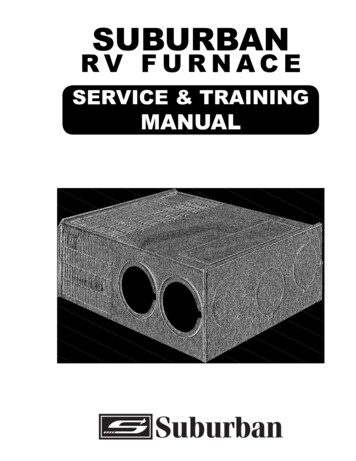
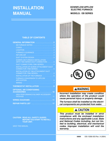
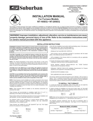
LEFT SIDEKNOCKOUT FOR CONNECTORFigure 6ABRBRLIMITSW. VESWITCHPWRBLON.C.Y GROUNDINGTERMINALYSAILSWITCHN.O.LIMITSW. N.C.POWERMODULEBOARDBRSWITCHELECTRODE-VALVEN.C.Y- CODE LECTRODETHERMOSTATN.O. BRVALVERBK -VVVALVEMOTORRBL THERMOSTATR 12 V.D.C.Y -12 V.D.C.BL THERMOSTATOY ALL WIRES ARE 18 AWG UNLESS OTHERWISE SPECIFIEDNOTE: IF ANY OF THE ORIGINAL WIRES AS SUPPLIEDWITH THE APPLIANCE MUST BE REPLACED, IT MUST BEREPLACED WITH WIRING MATERIAL HAVING ATEMPERATURE RATING OF AT LEAST 105 C.-12 VOLTS D.CCAUTION: DO NOT HI-POT (DIELECTRICHIGH VOLTAGE TEST) THIS UNIT AFTERINSTALLATION. TO DO SO MAY CAUSECOMPONENT DAMAGE AND VOIDSWARRANTY OF FURNACE.UNIT 100% FIRE CHECKED.NO. 18 250 C RADIX WIRE UL-3257340513Figure 7ILLUSTRATION OF MINIMUM SIDE CLEARANCES WITHA MINIMUM OF 24" CLEARANCE FRONT GRILL TONEAREST OBSTRUCTION.OBSTRUCTIONFigure 85
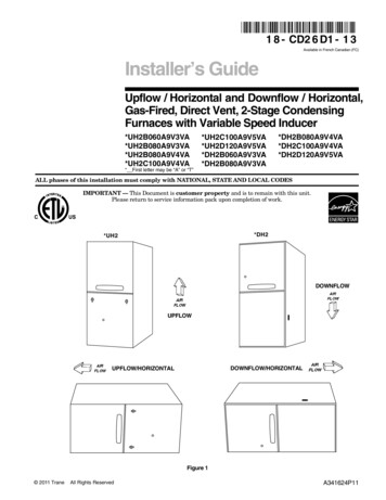
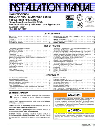
ILLUSTRATION OF MINIMUM CLEARANCES REQUIRINGADDITIONAL RETURN AIR TO FURNACEFURNACE CABINETTOPVIEWFURNACEWALLLEFT OR RIGHT SIDEIS LESS THAN 8".12" NT-16SEQ18" NT-20SEQ12 SQUARE INCHES OF ADDITIONALRETURN AIR IS REQUIRED IF LESSTHAN 8" TO SIDE WALL WITH 12"FRONT WALL CLEARANCE MODEL NT-16SEQOR 18" FRONT WALL CLEARANCE MODEL NT-20SEQ.Figure 91 3/4" MAX1/4"IF THE UNIT GRILLE IS FRAMED, FRAME MAY BE AT 0"CLEARANCES TO TOP & SIDES OF GRILLE AND EXTEND1 34" MAX. FROM BACK SIDE OF GRILLE. THE 1/4” BOTTOMCLEARANCE MUST BE MAINTAINED FOR RETURN AIRUNDER UNIT.Figure 10Suburban Division6
ILLUSTRATION DES ESPACES MINIMUM LIBRES SUR LESCÔTÉS AVEC UN ESPACE LIBRE DE 24" (POUCES) ENTRE LEGRILLAGE DE DEVANT ET L'OBSTRUCTION LA PLUS PROCHE.OBSTRUCTIONLa Figure 8ILLUSTRATION DES ESPACES MINIMUM LIBRES NÉCESSITANTRETOUR D'AIR ADDITIONNEL VERS L'APPAREIL DE CHAUFFAGE.CAISSE DE L'APPAREILDE CHAUFFAGEFENÊTRE D'OBSERVATION DU DESSUSDE L'APPAREIL DE CHAUFFAGEMURCÔTÉ GAUCHE OU DROITEST MOINS DE 8"(POUCES).12" NT-12SEQ18" NT-20SEQUN ESPACE DE RETOUR D'AIRADDITIONNEL DE 12 (POUCES)CARRÉS EST NÉCESSAIRE SIMOINS DE 8" (POUCES) VERSLE MUR DE CÔTÉ AVEC 18"(POUCES) D'ESPACE VER LEMUR DE DEVANT. MODEL NT-20SEQUN ESPACE DE RETOUR D'AIRADDITIONNEL DE 12 (POUCES)CARRÉS EST NÉCESSAIRE SIMOINS DE 8" (POUCES) VERSLE MUR DE CÔTÉ AVEC 12"(POUCES) D'ESPACE VER LEMUR DE DEVANT. MODEL NT-16SEQLa Figure 91 3/4" MAX1/4"Si la grille de l'appareil est encadrée, les dégagements deséparation doivent être nuls (0 po) entre les partiessupérieures/latérales de l'encadrement et la grille;l'encadrement doit dépasser de 1-3/4 po max. à l'arrière dela grille. Pour la partie inférieure, le dégagement de ¼ podoit être conservé pour permettre un retour d'air sousl'appareil.La Figure 10Suburban Division6
LE DIAMÈTRE DU TROU DANS LA PEAUEXTÉRIEURE PEUT ÊTRE 2 1/4" SI LA COUPED'OUVERTURE DANS LE MUR COMBUSTIBLEEST COUPÉE COMME ILLUSTRÉ DANS LESFIGURES 3 OU 4. LE DIAMÈTRE DU TROUDOIT ÊTRE 2 3/4" SI L'OUVERTURE DE 4 X 71/2 COMME MONTRÉ DANS LA FIGURE 4N'EST PAS COUPÉ AU-TRAVERS DU MURCOMBUSTIBLE.IMPORTANT:LE CAPOT DE LA VENTOUSE ETL'ASSEMBLAGE DU TUBE DOIVENT ÊTREINSTALLÉS PAR L'EXTÉRIEUR DE LAREMORQUE.LA PEAU DE LAREMORQUELE PLAN DUCALORIFÈRECALFATEZ PAR DERRIÈRE DU COUVERCLE DU SYSTÈMED'ADMISSION ET DE DÉCHARGE D'AIR, COMME INDIQUÉ, POURSCELLER ENTRE LES OUVERTURES D'ADMISSION ET DEDÉCHARGE ET POUR ÉVITER L'HUMIDITÉ A L'INTÉRIEUR DUCOMPARTIMENT DE L'APPAREIL DE CHAUFFAGE. APPLIQUEZ LECALFATAGE GÉNÉREUSMENT AUTOUR DU PÉRIMÊTRE DUCOUVERCLE DU SYSTEME D'ADMISSION ET DE DÉCHARGE D'AIRET SUR LA LIGNE DE CENTRE COMME INDIQUÉ. LE CALFATAGEDE LA LIGNE DE CENTRE EST ESSENTIEL.LE CAPOT DE LA VENTOUSE ETL'ASSEMBLAGE DU TUBED'ÉCHAPPEMENTLE TUBED'ADMISSIONL'INSTALLATION DU CAPOT DE LA VENTOUSELa Figure 6La Figure 6ABRBRINTERRUPTEURDE VOILE N.O.BLCONTACTEUR ENFIN DE COURSEN.C.MOTEURYBKBORNE MISEA LA TERREBL'YBRBLRYCARTE DEMODULEL'INTERRUPTEUREN YCONTACTEUR DE FINDE COURSE N.C.CARTE DEMODULEBRN.C.Y-ELECTRODE- THERMOSTATN.O. BRCLAPETRBK -VORANGENOIRBRUNBLEUROUGEJAUNEVERTVCLAPETMOTEUR CODE COULEUR CALIBRE 18 POUR TOUS LES CONDUCTEURS, SAUFINDICATION DIFFERÉNTE.NOTE: S'IL EST NECÉSSAIRE DE REMPLACER CERTAINSCONDUCTEURS D'ORIGINE, UTILISER DES CONDUCTEURSDOTÉS D'UN ISOLANT RÉSISTANT A UNÈ TEMPERATURED'AU MOINS 105 COBKBRBLRYGELECTRODEINTERRUPTEURDE VOILEN.O.OYR 12 V.D.C.BL THERMOSTATY -12 V.D.C.BL THERMOSTATL'INTERRUPTEUR EN MARCHE/ARRETR12 VOLTS C.CMISE EN GARDE: NE PAS SOUMETTRE CETAPPAREIL À UN TEST SOUS HAUTETENSION. CECI PROVOQUERAIT DESDOMMAGES ET RENDRAIT INVALIDE LAGARANTIE DE L'APPAREIL. L'APPAREIL ADÉJÁ ÉTÉ TESTÉ AU FEU-100%NO. 18 250 C FIL RADIX UL-3257-FR340513La Figure 75
BACK OF FURNACE CABINETTRAILER SKINPOWER SUPPLY & THERMOSTAT WIRESGAS INLET FOR ELECTRIC IGNITION MODELSSECURE UNIT IN PLACEWITH (2) SCREWSLa figure 2DEUX TROUS À TRAVERS LA PAROI DU VÉHICULE DIAMÈTRE 2 1/4 POPAROI DU VÉHICULESURFACE DU MONTAGEPEROI INTERNEENTRÉE DE GAZ POUR MODÈLEAVEC FLAMME DE VEILLECÂBLAGE-ALIMENTATIONÉLECTRIQUE ET THERMOSTATENTRÉE DE GAZ POUR MODÈLEAVEC ALLUMAGE ÉLECTRONIQUEIMMOBILISER AVEC DEUX VISLa Figure 3LE PLAN DU CAPOTDE LA VENTOUSE321613459167/64 D.(4) TROUX9132315161321616591612214LE CABINET DUCALORIFÈRELA SURFACEDE MONTAGE2 1/4 D. (2) LES TROUXAU-TRAVERS DE LA PEAUDE LA REMORQUELA VUE POSTÉRIÈRE DU CALORIFÈRELa Figure 44
Si l'alimentation en courant du calorifère sera d'un convertisseur, nousrecommandons que le système du convertisseur utilisé d'actionner le calorifèresoit câblé en parallèle avec la batterie. Ceci servira deux objets:1. Fournir une alimentation de tension constante au calorifère.2. Filtre aucunes pointes de tension c.a., ou surtensions.NOTE: Les modèles NT-16SEQ et NT-20SEQ de calorifère sont équipés avecun mécanisme d'igniteur électrique qui a une consommation d'énergie de .1 ampà 12 volts C.C.BRANCHEMENT DU THERMOSTATLe thermostat utilisé avec cet appareil ne doit avoir AUCUNE tension de sortiedans la tige de retour lorsqu’il n’y a aucun appel de chaleur ou que la commandeest réglée à « OFF » (arrêt).Situer le thermostat d’ambiance approxamativement 4 1/2 feet au-dessus duplancher sur une cloison interne où il n'est pas affecté par la chaleur d'aucunesource sauf l'air des locaux. Brancher les fils du thermostat aux fils bleus enlaissant la fiche d'alimentation en courant sur le côté droit du calorifère. (Voir leschéma de câblage.) Si l’appareil de chauffage est doté d’un thermostat munid’dun anticipateur réglable, régler l’anticipateur a 0,7A. Choisir une valeur plusélevée si on souhaite augmenter la durée des périodes de chauffage. Choisir unevaleur moins élevée si on souhaite diminuer la durée des periodes de chauffage.Ne pas modifier le réglage de l’anticipateur de plus de 0,5A à chaque fois.INSTALLATION DU CONDUIT D ÉVACUATIONLe circuit d’évacuation doit être installé de telle manière que la bouche dedécharge se trouve dans la même zone de pression atmosphérique que la prised’air de combustion. Les tubes de décharge et d admission d’air doivent êtreinstallés depuis l’extérieur, et traverser la paroi du VR, pour atteindre les bouchesd’admission et d’évacuation de d’appareil de chauffage.Avertissement! Ne pas modifier le système d évacuation fourni avec cetappareil de chauffage. Toute modification provoquera une déficience del'installation pouvant susciter un fonctionnement dangereux de l’appareil.Ne jamais faire fonctionner l’appareil lorsque la bouche de cécharge estobstruée.2. Insérer le tube d’admission d air à travers la paroi du VR; insérer celui-cidans la prise d’air de l’appareil de chauffage (voir la figure 1). Il doit y avoir unchevauchement d’au moins 1/2 po du tube dans le raccord.3. Insérer le tube de la bouche de décharge à travers la paroi du VR, pourl’insérer dans l’orifice de décharge de l’appareil de chauffage (voir la figure 1). Unchevauchement d’au moins 1 1/4 po est nécessaire.4. Fixer la bouche de décharge sur la paroi du VR avec les six (6) vis fournies.Veiller à ne pas installer la bouche de décharge à l’envers; les mot «Suburban»doivent être parfaitement lisibles (à l’endroit).Du fait de la température élevée générée, on doit installer l’appareil horsdes espaces de circulation et à distance des meubles et rideaux.Signaler aux adultes et aux enfants les dangers des températures desurface élevées. On doit toujours se tenir à distance pour éviter lesbrûlures ou l'inflammation de vêtements.Superviser étroitement les jeunes enfants qui séjournent dans la pièceoù l'appareil est installé.Ne pas placer des vêtements ou autres matériaux inflammables surl'appareil ou à proximité.Avant de faire fonctionner l'appareil, réinstaller tout écran ou autreorgane de sécurité déposé pour des opérations d'entretien.Veiller à ce qu'il n'y ait jamais de matériaux combustibles, essence etautre produit liquide ou gazeux inflammable au voisinage de l'appareil.Seul un personnel qualifié est habilité à effectuer l'installation ou desréparations. Faire inspecter l'appareil avant l'emploi et au moins une foispar an par un technicien qualifié. Un nettoyage peut être nécessaire plusfréquemment si des tapis, articles de literie, etc. génèrent une quantitéexcessive de peluches. Il est impératif que les compartiments desorganes de commande, les brûleurs et les passages de circulation del'air de l'appareil soient maintenus propres.Mise en garde : On ne doit pas prélever l’air de combustion dans l espacede séjour. Tout l'air de combustion doit provenir de l’atmosphère extérieure.Tout gaz de combustion doit être rejeté dans l’atmosphère extérieure- et jamais à l’intérieur du VR. Par conséquent il est essentiel d’installerconvenablement les conduits d’admission d’air et d’évacuation.1. Appliquer un composé de calfeutrage sur la paroi du VR derrière la bouche dedécharge (voir la figure 6). Appliquer le produit de calfeutrage sans parcimoniesur le périmètre de la bouche de décharge, et en travers de la zone centrale (voirl’illustration).L'INSTALLATION DU TUBE DE LA VENTOUSE"X"1 3/8"TUBE DE LA VENTOUSE(L'ÉCHAPPEMENT) 8" X 2" D.E.L'ASSEMBLAGE DU TUBE DE LAVENTOUSE(L'ADMISSION) VOIR LE DIAGRAMMELA PEAU DE LA REMORQUEY"LE CAPOT DE LAREMORQUE2 1/4"DIA.1 1/4" CHEVAUCHEMENTMINIMUM2 1/4"DIA.7 1/2"SURFACE DE MONTAGE1/2" CHEVAUCHEMENT MINIMUM21"LA LONGUEUR SEULEMENTLE TUBE NORMAL FOURNI AVEC LE CALORIF ÈRE. LES TUBESSPÉCIALS, SI ON A BESOIN, DOIVENT ÊTRE COMMANDÉS.25 1/2" À 27 3/4"2" D.E. X 7 1/4" SPÉCIALX05070823 1/4" À 25 1/2"2" D.E. X 5" *NORMALX050712NE JAMAIS INSTALLER LE TUBE D'ÉCHAPPEMENT AVEC UNCHEVAUCHEMENT DE MOINS DE 1 1/4", OU LE TUBED'ADMISSION AVEC UN CHEVAUCHEMENT DE MOINS DE 1/2'.21" À 23 1/4"2" D.E. X 2 3/4" SPÉCIALX050711DIMENSION "X"LA RÉFÉRENCE DU TUBE D'ADMISSIONLa Figure 13
L’INSTALLATION DU CALORIFÈRELa caisse de l’appareil doit dépasser de 1 3/8 po à travers le placard comme on levoit à la figure 1. Ce dépassement de 1 3/8 po est nécessaire pour que la grille decalandre avant puisse s’accrocher convenablement sur la caisse de l’appareil.On doit également prévoir les dégagements de séparation adéquats autour de lacaisse de l’appareil pour permettre l’accès pour l’entretien.1. Situer le calorifère près du centre en longueur de la voiture. Ne pas installer labouche de décharge de l’appareil orientée vers l’avant du véhicule.2. Choisir un endroit pour l’installation de loin des fils, des tuyaux, etc. qui peutintervenir dans l’installation. Adhérer aux espaces libres minimums suivants ducabinet de calorifère à la construction combustible.Les Côtés 5/8”Le Dos 0”Le Plancher 0”Le Sommet 5/8”b. Si vous ne voulez pas couper l’ouverture de 4” x 7 1/2”, situer la lignecentrale du tube d’échappement et d’entrée comme montré à la Figure 4. Puis,couper deux (2) troux du diamètre 2 3/4" au travers de la peau de la voiture etaussi le mur combustible de la voiture comme illustré à la Figure 6. Avoir soin ensituant la ligne centrale du tube d'échappement et d'entrée aussi qu'en coupantles troux pour assurer une espace libre de 3/8" autour des tubes d'échappementet d'entrée aux matériaux combustibles.10. Veuillez vous référer au dessin à la Figure 1 et choisir la portée pour quela dimension "X" tombe. La longueur du tube d'entrée directement à la gauchede la portée choisie est la longueur exigée. NOTE: L'assemblage du tubed'échappement de la longueur de 7 3/4" accommodera toutes les profondeursd'installation approuvées - seulement le tube d'entrée doit être ondonné quandc'est nécessaire.On ne doit en aucun cas couper ou modifier le tube d’admission d’air standard de5 po pour l’adapter à un appareil de 21-23 1/4 po.12. REMARQUE: ADAPTATEUR DE CONDUIT DE DÉCHARGE-FACULTATIF- La caisse de l’appareil comporte un opercule arrachable de diamètre 4 po surle côté gauche (voir figure 6A). On peut fixer un raccord de diamètre 4 po à cetendroit pour le raccordement d'un conduit de décharge de l'air chaud (longueurmaximum de 10 po).On doit ménager les dégagements de séparation suivants entre la grille dedécharge de l’air chaud et les matériaux combustibles (valeurs minimales): VoirFigure 10 pour le dégagement de séparation nel (0 po) de la grille (grille avecencadrement).11. Fixer l’appareil de chauffage au plancher en utilisant les deux (2) trous prévusà cet effect dans le bâti de l’appareil (voir la figure 2 ou 3).REMARQUE: Le dégagement de séparation sur les côtés et au sommet de lacaisse de l’appareil peut être nul dans le cas d’une installation à travers un murd’épaisseur jusqu’à 2,5 po (voir figure 2).Modèles NT-16SEQ, NT-20SEQOUCôté gauche - 1 poCôté droit - 8 poSommet - 1 poAvant - 24 poPlancher - 1/4 poCôté gauche - 8 poCôté droit - 1 po(Voir Figure 8)Dégagement De Séparation Avant RéduitCôtés - 0 po*Avant - 18 po NT-20SEQSommet - 1 poAvant - 12 po NT-16SEQPlancher - 1/4 poBRANCHEMENT À LA SOURCE DE GAZOn trouve sur le côté droit de l’appareil un raccord évasé de 3/8 po pour leraccordement de la canali
3-The furnace must be electrically grounded in accordance with the latest edition of the National Electrical Code NFPA 70. 4-The installation of the furnace shall be in accordance with any applicable local codes and regulations. In Canada, the furnace must be installed in accordance with: 1-Standard CAN/CSA Z240.0.2-08 Recreational Vehicles