Transcription
Mediant 1000BMediant 800SIP ProtocolDeployment NoteDeploying AudioCodes Mediant 1000B / 800with AltiGen MAX Communications Server 7.0December 2014Document #: LTRT-
Deployment NoteContentsTable of Contents1Introduction . 71.11.21.32Hardware . 92.12.22.32.43Opening the Web Interface .13Step 1: Disable the DHCP Server . 14Step 2: Set VoIP IP Parameters . 15Step 3: Set Syslog Parameters . 16Step 4: Configure PSTN Trace Parameters . 17Step 5: Set SIP Advanced Parameters . 18Step 6: Set TDM Bus Parameters. 19Step 7: Set PSTN Trunk Parameters . 20Step 8: Set IPMedia Parameters . 21Step 9: Set SIP General Parameters . 22Step 10: Set Proxy and Registration Parameters . 23Step 11: Set VoIP Coders Parameters . 24Step 12: Set VoIP Trunk Group Parameters . 25Step 13: Set VoIP Trunk Group Settings . 26Step 14: Configure the IP to Trunk Group Routing . 27Step 15: Set Digital Gateway Parameters. 28Step 16: Configure Outbound Trunk Routing . 29Step 17: Configure Inbound Trunk Routing . 30Configuring the MAX Communications Server. 315.15.25.36Step 1: Ground the Chassis.11Step 2: Insert the T1/E1 Module . 11Step 3: Connect the Gateway to a Provisioning Computer . 12Configuring the AudioCodes Gateway . .154.164.174.185Network Topology .9Package Contents .9Front Panel .9Rear Panel .10Setting up the Hardware . 113.13.23.34Intended Audience .7About AudioCodes' Mediant Gateway .7Related Documentation .7Step 1: Configure the SIP Trunk in Enterprise Manager . 31Step 2: Configure the SIP Trunk in MaxAdministrator . 35Troubleshooting .40Verifying Interoperability . 42Appendix A: Analog Configuration . 44Front Panel .44Step A1: Add a New Rule To the Trunk Group Table . 45Step A2: Configure Analog Gateway Parameters . 46AltiGen MAX Communications Server3February 2014
AltiGen MAX Communications ServerStep A3: Configure Automatic Dialing . 47Step A4: Verify Interoperability .48Appendix B: SIP Configuration . 49Step B1: Change the Default Proxy Option to No . 49Step B2: Enable IP-to-IP.50Step B3: Increase Media Channels .51Step B4: Remove the Default Proxy Set . 52Step B5: Configure IP Group 1 for MaxCS. 53Step B6: Configure IP Group 2 for the SIP Trunk. 54Step B7: Configure Proxy Set 1 for MaxCS . 55Step B8: Configure Proxy Set 2 for the SIP Trunk . 56Step B9: Configure Coder Group 1 for MaxCS . 57Step B10: Configure Coder Group 2 for the SIP Trunk . 58Step B11: Configure IP Profile 1 for MaxCS . 59Step B12: Configure IP Profile 2 for the SIP Trunk . 60Step B13: Remove Plus Sign in Destination Phone Number . 61Step B14: Remove Plus Sign in the Source Phone Number . 62Step B15: Configure Outbound IP Routing Rules . 63Step B16: Configure Inbound IP Routing Rules . 64Step B17: Verify Interoperability .65Appendix C: AudioCodes ini File . 66AudioCodes Mediant 1000B and Mediant 8004Document #: LTRT-39265
AltiGen MAX Communications ServerNoticesNoticeThis document shows how to deploy AudioCodes' Mediant 800 / Mediant 1000B with theAltiGen MAX Communications Server in your enterprise.Information contained in this document is believed to be accurate and reliable at the time ofprinting. However, due to ongoing product improvements and revisions, AudioCodes cannotguarantee accuracy of printed material after the Date Published nor can it acceptresponsibility for errors or omissions. Before consulting this document, check thecorresponding Release Notes regarding feature preconditions and/or specific support in thisrelease. In cases where there are discrepancies between this document and the ReleaseNotes, the information in the Release Notes supersedes that in this document. Updates tothis document and other documents as well as software files can be downloaded byregistered customers at http://www.audiocodes.com/downloads. Copyright 2014 AudioCodes Ltd. All rights reserved.This document is subject to change without notice.Date Published: June-2014TrademarksAudioCodes, AC, AudioCoded, Ardito, CTI2, CTI², CTI Squared, HD VoIP, HD VoIPSounds Better, InTouch, IPmedia, Mediant, MediaPack, NetCoder, Netrake, Nuera, OpenSolutions Network, OSN, Stretto, TrunkPack, VMAS, VoicePacketizer, VoIPerfect,VoIPerfectHD, What’s Inside Matters, Your Gateway To VoIP and 3GX are trademarks orregistered trademarks of AudioCodes Limited. All other products or trademarks areproperty of their respective owners. Product specifications are subject to change withoutnotice.WEEE EU DirectivePursuant to the WEEE EU Directive, electronic and electrical waste must not be disposedof with unsorted waste. Please contact your local recycling authority for disposal of thisproduct.Customer SupportCustomer technical support and service are generally provided by AudioCodes’Distributors, Partners, and Resellers from whom the product was purchased. For technicalsupport for products purchased directly from AudioCodes, or for customers subscribed toAudioCodes Customer Technical Support (ACTS), contact support@audiocodes.com.AudioCodes Customer Support CenterAmericas: 1-732-652-1085 or 1-800-735-4588Elsewhere: 800-735-2244 Or te audiocodes.com/supportiSupport (on-line ticket management)https://crm.audiocodes.com/OA HTML/jtflogin.jspProduct Documentation and ssional vicesAltiGen MAX Communications Server5February 2014
AltiGen MAX Communications ServerAbbreviations and TerminologyEach abbreviation, unless widely used, is spelled out in full when first used.Note: Throughout this manual, unless otherwise specified, the term device refersto the AudioCodes Mediant 800 and Mediant 1000B.AudioCodes Mediant 1000B and Mediant 8006Document #: LTRT-39265
AltiGen MAX Communications Server11. IntroductionIntroductionThis Deployment Note shows how to deploy the hardware and configure the gateway tointeroperate with the AltiGen MAX Communications Server Release 7.0 Premise or PrivateCloud.This Note covers how to configure T1/E1 connectivity. Appendix A gives instructions foranalog configuration; Appendix B covers the configuration for SIP trunks.The Note does not cover the gateway's other functionalities. See Related Documentation,for a list of related documentation items.The instructions in this Note apply to a deployment with gateway software version6.40A.039.008 or later.IMPORTANT: AltiGen does not provide general configuration support forAudioCodes products. A support agreement with AudioCodes is required.1.1Intended AudienceThe Note is intended for AltiGen dealers, system administrators and network administratorswho will deploy the AudioCodes Mediant 800 or 1000B gateway to interoperate with theAltiGen MAX Communication Server release 7.0.1.2About AudioCodes' Mediant GatewayAudioCodes' Mediant gateway provides a bridge between the AltiGen MAXCommunications Server and the PSTN network. The gateway transparently manages theprotocol translation and interworking between the two systems.1.3Related DocumentationRelated documentation is: Mediant 1000B Quick Guide Mediant 1000B SIP User’s Manual (Mediant 1000 MSBG User's Manual Ver. 6.4) Mediant 1000B SIP Installation Manual Release Notes Configuring Syslog Technical Note (Configuring Syslog Technical Note Ver. 6.2) Errata-Addendum for SIP CPE Documentation Restoring Factory Defaults Technical Note (Restoring Factory Defaults ConfigurationNote Ver. 6.4) BootP Technical Note Customer Case Reporting Procedures SIP CPE Product Reference Manual CPE SIP Troubleshooting GuideAltiGen MAX Communications Server7February 2014
AltiGen MAX Communications ServerAudioCodes' documentation is available for download from the AudioCodes web site,http://www.audiocodes.com after registering free of charge. In the web site, click theServices tab and choose the Product Documentation & Software menu.AudioCodes Mediant 1000B and Mediant 8008Document #: LTRT-39265
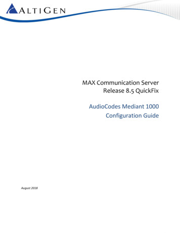
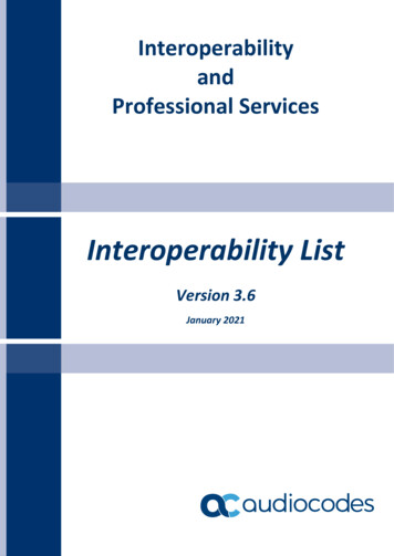
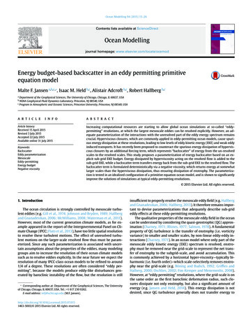
AltiGen MAX Communications Server22. HardwareHardwareThis section itemizes the hardware components and shows how to connect the gateway toa provisioning computer.2.1Network TopologyThis illustration shows the gateway and server deployed in the network:T1/E1PSTN2.2GatewayMAXCSSIP TrunkPackage ContentsYou should receive one large box containing the gateway and the power cord. If the T1/E1component wasn't preinstalled in the chassis, it will be provided in a separate box. Youmust provide an Ethernet cable and a T1 cable. Ensure that your Mediant 1000B Gatewaypackage includes the following items: Four anti-slide bumpers for desktop installation One 19-inch rack mounting kit (two flanges and six screws) RS-232 serial cable adaptor for serial communication between the Mediant1000B PSTN Gateway functionality (flat connector) and a pc (red-yellow DB-9connector) Two mounting brackets for 19-inch rack mounting One AC power cordIt's recommended to retain all AudioCodes receipts and documents.missing or damaged, contact your AudioCodes sales representative.2.3If any items areFront PanelThis shows and explains the front panel:311452T1Telephony PortsPorts for CMX module, the CPU for VoIP gateway functionality, with 3LAN and 1 WAN port. You will use one of the LAN ports. On (Green) – Ethernet link established Flashing (Green) – Data received or transmitted Off – No Ethernet link2CRMX or CMX3Power 1Spare power supply slot.4Power 2Main power supply slot.5FanExtractable fan tray.AltiGen MAX Communications Server9February 2014
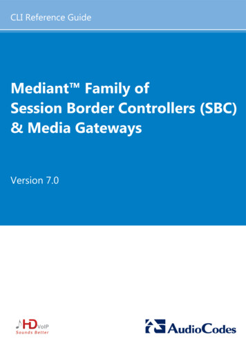
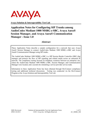
AltiGen MAX Communications Server2.4Rear PanelThis shows and explains the rear panel:1Protective earthing (grounding) screw.2ESD3100-240V 2A50-60 HzMain AC power supply outlet.4100-240V 2A50-60 HzOptional, redundant AC power supply outlet.5OSN3OSN3 module (not required for AltiGen deployment; may or may not beincluded).6 O O Serial interface port (RJ-45).Electrostatic Discharge (ESD) socket.7Gigabit Ethernet interface port (RJ-45) - automatic detection andswitching between 10Base-T, 100Base-TX, and 1000Base-T datatransmissions (Auto-Negotiation), as well as auto-wire switching forcrossed cables (Auto-MDI/X).8USB 2.0 port.9HDMXHard disk drive module for OSN3 platform.AudioCodes Mediant 1000B and Mediant 80010Document #: LTRT-39265
AltiGen MAX Communications Server33. Setting up the HardwareSetting up the HardwareThis section shows how to set up the hardware components.3.1Step 1: Ground the ChassisThe chassis must be permanently connected to earth (ground) using an equipmentearthing conductor. To ground the chassis:3.21.Connect an electrically earthed strap of 16 AWG wire (minimum) to the chassis'earthing screw (located on the left end of the rear panel) using the supplied washer.2.Connect the other end of the strap to a protective earthing in accordance with theregulations enforced in the country of installation.Step 2: Insert the T1/E1 ModuleIf the T1/E1 module was not preinstalled, you must insert it into the chassis.Note: Before inserting the module into the chassis, remove the clear tape whichcovers the module's gold edge and which protects the module’s BUS line.If you do not remove it, the module will not function and you may causeirreversible damage to the chassis.Remove the tapeAltiGen MAX Communications Server11February 2014
AltiGen MAX Communications Server To insert the T1/E1 module into the chassis:3.31.Remove the tape from the edge of the module.2.Use a Phillips screwdriver to remove the black metal cover plate protecting the moduleslot on the front panel.3.Insert the module into the first available slot (slots 1-5); align the module with the railsin the slot in the following module orientation depending on whether you are insertingit in the top or bottom-row slots: Top-row slots: Ensure that the module is orientated so that the port number labelsare located at the bottom of the module's front panel. This orientation isconsidered face up. Bottom-row slots: Ensure that the module is orientated so that the port numberlabels are located at the top of the module's front panel. This orientation isconsidered face down.4.Push the module into the slot and press on it firmly to ensure it is fully inserted.5.Use a flathead screwdriver to tighten the module's mounting pins.Step 3: Connect the Gateway to a ProvisioningComputerYou must configure the gateway with a direct connection to a provisioning computer beforeyou connect the gateway to the LAN. Do not connect the gateway to your corporatenetwork until you have configured it. The gateway comes with a DHCP server that must bedisabled, or else network connectivity problems may occur. To connect the gateway to a provisioning computer:1.On the rear panel, connect the left power socket to an electrical outlet using thesupplied AC power cord. The power LED on the front panel of the power supplyshould be green. If the LED is off, there may be a power supply problem.2.Use an RJ-45 Ethernet cable to connect the network port on the provisioning PCdirectly to the LAN port on the gateway.3.Make sure that this PC is configured to automatically obtain IP addresses. Thegateway’s embedded DHCP server (enabled by default) allocates an IP address to thePC when you connected the two devices. If this allocation does not automaticallyoccur, manually assign the IP address 192.168.0.100.4.Open a Web browser. In the URL field, enter the gateway default VoIP / ManagementLAN IP address (i.e., 192.168.0.2).5.When the Login page opens, use the default, case-sensitive user name (Admin) andpassword (Admin) and click OK; the Web-based interface opens on the Home page.AudioCodes Mediant 1000B and Mediant 80012Document #: LTRT-39265
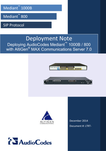
AltiGen MAX Communications Server44. Configuring the AudioCodes GatewayConfiguring the AudioCodes GatewayThis section shows how to customize AudioCodes' software settings for interoperabilitywith the MAX Communications Server.4.1Opening the Web InterfaceThe Web interface's Home page shows components status. Click any component in thegraphic representation of the gateway to display operational information or additionalconfiguration options.Burn button: Use itto write configuration changes toflash memoryDevice Actions:Use this menu toreset the gatewayand load or saveconfiguration filesChoose 'Full'instead of ‘Basic’Shows real-time status ofcomponents (click acomponent for details onits status)Navigation paneImportant!In order to configure the gateway via this tool, you must have the menu set to“Full.” If you leave the menu set to “Basic,” you will not see some of the menuchoices and some options on various pages will not appear. Be especiallycareful to check this menu setting after you have logged out and logged backin again – make sure the application has not automatically reverted to “Basic”menu mode.In addition, if you notice that you are working in “Basic” menu mode and thenchoose “Full,” it is best to leave the page you are on and then re-open it. Insome cases, switching to Full menu mode will not automatically refresh thecurrent page.AltiGen MAX Communications Server13February 2014
AltiGen MAX Communications Server4.2Step 1: Disable the DHCP ServerDisable the DHCP server to avoid conflict with another DHCP server during initialconfiguration. To disable:1.Choose Data Data Services DHCP Server.2.If the WAN Ethernet service is shown as Enabled, click the pencil iconrow to edit the settings.3.From the menu, select Disabled and click OK.AudioCodes Mediant 1000B and Mediant 80014on thatDocument #: LTRT-39265
AltiGen MAX Communications Server4.34. Configuring the AudioCodes GatewayStep 2: Set VoIP IP ParametersSet the gateway IP address information for your system.1.Choose VoIP Network IP Interfaces Table.2.Click the 0 (zero) Index button; an Edit button appears. Click it and configure networksettings corresponding to your network IP address scheme:3. Set ‘IP Address’ to the AudioCodes gateway’s IP address Set ‘Prefix length’ to the subnet mask length in CIDR notation Set ‘Gateway’ to the default gateway’s IP address (Optional) DNS: Enter the primary DNS server IP address (and the secondary ifrelevant) Leave the remaining options set to their default settingsClick Apply then Done and then Burn; the gateway reboots and starts using the newIP address. Maintain the cabled connection between the gateway LAN port and theprovisioning computer.Note: Reset the gateway for parameters markedInterface Name' in the screen above.AltiGen MAX Communications Server15to take effect, e.g., 'WANFebruary 2014
AltiGen MAX Communications Server4.4Step 3: Set Syslog ParametersSyslog traces are important for troubleshooting. AudioCodes recommends that you set upa Syslog server. To set up a Syslog server:1.In the left navigation pane, click Configuration.2.Choose System Syslog Settings3.Set these parameters:4. Set 'Enable Syslog' to Enable Set 'Syslog Server IP Address' and 'Syslog Server Port' Set 'Debug level' to 5 Make sure all parameters in the lowermost pane are selectedClick Submit.AudioCodes Mediant 1000B and Mediant 80016Document #: LTRT-39265
AltiGen MAX Communications Server4.54. Configuring the AudioCodes GatewayStep 4: Configure PSTN Trace ParametersNext, configure settings for the trace log. To configure the trace log:1.In the browser window, enter the network IP address of the AudioCodes gatewayappended with this string: /AdminPage. Refer to the next figure for an example.2.In the left pane, click ‘ini Parameters.’3.In the ‘Parameter Name’ field, enter TRACELEVEL.4.In the ‘Enter Value’ field, enter 1.5.Click Apply New Value.6.In the ‘Parameter Name’ field, enter PSTNRESERVED3.7.In the ‘Enter Value’ field, enter 8.8.Click Apply New Value.9.To return to the AudioCodes program, in the left pane click Back to Main.AltiGen MAX Communications Server17February 2014
AltiGen MAX Communications Server4.6Step 5: Set SIP Advanced ParametersCDR (Call Data Record) information is helpful when interpreting Syslog traces. Set theparameters shown in this subsection to provide robust CDR report details.1.Choose VoIP SIP Definitions Advanced Parameters2.Set these parameters: 3.Set 'Disconnect on Broken Connection' to No Set 'CDR Server IP Address' to the same address as the Syslog server Set 'CDR Report Level' to Start & End Connect CallClick Submit.AudioCodes Mediant 1000B and Mediant 80018Document #: LTRT-39265
AltiGen MAX Communications Server4.74. Configuring the AudioCodes GatewayStep 6: Set TDM Bus ParametersThe PSTN gateway's TDM bus must be configured. The parameters shown belowconfigure the signal encoding used between the AudioCodes gateway and the AltiGenMAX Communications Server. To set TDM bus parameters:1.Choose VoIP TDM TDM Bus Settings2.Set this parameter: 3.Set 'PCM Law Select' to MuLawClick Submit.AltiGen MAX Communications Server19February 2014
AltiGen MAX Communications Server4.8Step 7: Set PSTN Trunk ParametersThis step shows how to set PSTN trunk parameters. To set PSTN trunk parameters:1.Choose VoIP PSTN Trunk Settings.2.Set these parameters: Set 'Protocol Type' to T1 NI2 ISDN Set 'Clock Master' to Recovered For 'Line Code', select B8ZS (bipolar 8-zero substitution) for T1 trunks Set 'Framing Method' to T1 FRAMING ESF CRC6 Set 'ISDN Termination Side' to User side3.Click Submit.4.Click the Burn button to save the configuration changes to flash memory.Note: If these parameters have previously been set, you may need to click Deactivate before you canadjust them.AudioCodes Mediant 1000B and Mediant 80020Document #: LTRT-39265
AltiGen MAX Communications Server4.94. Configuring the AudioCodes GatewayStep 8: Set IPMedia ParametersThis step shows how to set IPMedia parameters. To set IPMedia parameters:1.Choose VoIP Media IPMedia Settings.2.Set these (optional) parameters: Set 'IPMedia Detectors' to Enable Set 'Enable AGC' to Enable3.Click Submit.4.Click Burn.AltiGen MAX Communications Server21February 2014
AltiGen MAX Communications Server4.10Step 9: Set SIP General ParametersThis step shows how to configure the gateway SIP parameters. To configure the gateway SIP parameters:1.Choose VoIP SIP Definitions General Parameters.2.Set the following parameters:3. Set ‘NAT IP Address’ to the MaxCS server's public IP address Set 'Enable Early Media' to Enable (Recommended) Set 'Session Expires Time' to 300 (or your preferred duration) Make sure that 'SIP Transport Type' is set to UDPClick Submit.AudioCodes Mediant 1000B and Mediant 80022Document #: LTRT-39265
AltiGen MAX Communications Server4.114. Configuring the AudioCodes GatewayStep 10: Set Proxy and Registration ParametersThis step shows how to configure the address (IP address or FQDN) of the MAX CS SIPtrunk that communicates with the gateway. The PSTN gateway forwards all calls from thePSTN to the SIP trunk using this address. The address is configured in the PSTN gatewayas a proxy server, i.e., the SIP trunk acts as a proxy server (without registration) for thePSTN gateway. To set proxy and registration parameters:1.Choose VoIP SIP Definitions Proxy & Registration.2.Set 'Use Default Proxy' to Yes.3.Click the arrow below the 'Use Default Proxy' parameter to open the Proxy Set Table.4.On row 1, set 'Proxy Address' to the MaxCS server's IP address and port 5060.5.Set 'Transport Type' to UDP.6.Click Submit.7.Click Burn.AltiGen MAX Communications Server23February 2014
AltiGen MAX Communications Server4.12Step 11: Set VoIP Coders ParametersThis step shows how to set the VoIP coder parameters.The PSTN gateway communicates with the SIP trunk using either the G.711 A-law orG.711 µ-law (Mu-Law) voice coder.In addition, silence suppression can be enabled per coder. To configure the VoIP coder parameters:1.Choose VoIP Coders and Profiles Coders.2.For 'Coder Name', select the codec type.3.For each coder name, choose whether you want Silence Suppression. Silencesuppression saves network bandwidth (not critical for LAN) but may cause smallartifacts when voice reestablishes. AudioCodes recommends setting 'SilenceSuppression' to Disabled.4.Click Submit.5.Click Burn.AudioCodes Mediant 1000B and Mediant 80024Document #: LTRT-39265
AltiGen MAX Communications Server4.134. Configuring the AudioCodes GatewayStep 12: Set VoIP Trunk Group ParametersThis step shows how to set the Trunk Group parameters.To enable trunks, you need to assign them to trunk groups. Trunk groups are local entitiesthat the SIP trunk will use for call routing. To set the VoIP Trunk Group parameters:1.Choose VoIP GW and IP to IP Trunk Group Trunk Group.2.For each trunk group, indicate these parameters: Set 'Module’ to the module number and type (e.g., PRI) on which the trunks arelocated Set 'From Trunk' (first available) and 'To Trunk' (last) to the physical trunk range For 'Channels,' specify the B-channels (e.g., 1-24) that you want to enable Set 'Phone number' to the number for the first channel; the rest will be assignedsequentially Set 'Trunk group ID' to the ID group3.Click Submit.4.Click Burn.AltiGen MAX Communications Server25February 2014
AltiGen MAX Communications Server4.14Step 13: Set VoIP Trunk Group SettingsThis step shows how to set the VoIP Trunk Group Settings. To set the VoIP Trunk Group Settings:1.Choose VoIP GW and IP to IP Trunk Group Trunk Group Settings.2.For each trunk group, set 'Channel Select Mode' to Descending and click Submit.Note: Descending assumes that the PSTN uses Ascending mode. Set thechannel mode that is the opposite of the PSTN mode to avoid possible glareconditions (when the same b-channels are allocated for both incoming andoutgoing calls).See the AudioCodes User's Manual for a full explanation of all supportedchannel select modes.AudioCodes Mediant 1000B and Mediant 80026Document #: LTRT-39265
AltiGen MAX Communications Server4.154. Configuring the AudioCodes GatewayStep 14: Configure the IP to Trunk Group RoutingAfter enabling the trunks and assigning them to trunk groups, you must configure how thePSTN gateway selects trunk channels belonging to a group for receiving calls. To configure the IP to Trunk Group routing:1.Choose VoIP GW and IP to IP Routing IP to Trunk Group Routing.2.Set 'Source IP Address' to the IP address of the MaxCS Server.3.Click Submit.Do not put an asterisk in the “Source IP Address” field. If you do, anyonecan use the Mediant 1000 gateway to make PSTN calls.AltiGen MAX Communications Server27February 2014
AltiGen MAX Communications Server4.16Step 15: Set Digital Gateway ParametersHere's how to set the Digital Gateway Parameters. To set the Digital Gateway Parameters:1.Choose VoIP GW and IP to IP Digital Gateway Digital Gateway Parameters.2.Set 'B-Channel Negotiation' to Preferred.3.Click Submit.AudioCodes Mediant 1000B and Mediant 80028Document #: LTRT-39265
AltiGen MAX Communications Server4.174. Configuring the AudioCodes GatewayStep 16: Configure Outbound Trunk RoutingThis section shows how to configure outbound call routing. The Outbound IP Routing tablelets you configure up to 180 Tel-to-IP or outbound IP call routing rules. You will create arule to indicate that all outbound calls should route through MaxCS. To configure outbound trunk routing:1.Choose VOIP GW and IP to IP Routing Tel to IP Routing.2.For routing index 1 (the first row), specify that all outgoing calls are included in thisrule. Do this by entering the asterisk character (*) in the first five fields, as shown inthe next figure.3.For ‘Dest. IP Address’ enter the IP address of the MaxCS server, to indicate that all
Configuring Syslog Technical Note (Configuring Syslog Technical Note Ver. 6.2) Errata-Addendum for SIP CPE Documentation Restoring Factory Defaults Technical Note (Restoring Factory Defaults Configuration Note Ver. 6.4) BootP Technical Note Customer Case Reporting Procedures SIP CPE Product Reference Manual