Transcription
Avaya Solution & Interoperability Test LabApplication Notes for Configuring SIP Trunks amongAudioCodes Mediant 1000 MSBG e-SBC, Avaya Aura Session Manager, and Avaya Aura CommunicationManager - Issue 1.0AbstractThese Application Notes describe a sample configuration for a network that uses AvayaAura Session Manager to connect AudioCodes Mediant 1000 MSBG e-SBC and AvayaAura Communication Manager using SIP trunks.The AudioCodes Mediant 1000 MSBG e-SBC is a SIP Session Border Controller (SBC) thatmanages and protects the flow of SIP signaling and related media across an untrusted IPnetwork. The compliance testing focused on telephony scenarios between an enterprise site,where the AudioCodes Mediant 1000 MSBG e-SBC, Session Manager, and CommunicationManager were located, and a second site simulating a service provider service node.Information in these Application Notes has been obtained through DevConnect compliancetesting and additional technical discussions. Testing was conducted via the DevConnectProgram at the Avaya Solution and Interoperability Test Lab.MJH; Reviewed:SPOC 4/6/2011Solution & Interoperability Test Lab Application Notes 2011 Avaya Inc. All Rights Reserved.1 of 51AC MSBG SM
1. IntroductionThese Application Notes describe a sample configuration for a network that uses Avaya Aura Session Manager to connect AudioCodes Mediant 1000 MSBG e-SBC and Avaya Aura Communication Manager using SIP trunks.The Mediant 1000 MSBG is an all-in-one multi-service access solution for Service Providersoffering managed services and distributed Enterprises. This multi-service business gateway isdesigned to provide converged Voice & Data services for business customers at wire speed,while maintaining SLA parameters for voice quality.The compliance testing focused on telephony scenarios between an enterprise site, where theAudioCodes Mediant 1000 MSBG e-SBC, Session Manager, and Communication Manager werelocated, and a second site simulating a service provider service node.2. General Test Approach and Test ResultsThe general test approach was to make calls between the main enterprise site and the 2nd sitesimulating a service provider service node using various codec settings and exercising commontelephony features.2.1. Interoperability Compliance TestingThe compliance testing focused on interoperability between AudioCodes Mediant 1000 MSBGe-SBC and Session Manager / Communication Manager by making calls between the enterprisesite and a second site simulating a service provider service node that were connected through theMediant 1000 MSBG e-SBC using direct SIP trunks. The following functions and features weretested: Calls from both SIP and non-SIP endpoints between sites.G.711MU and G.729AB codec support.Proper recognition of DTMF transmissions by navigating voicemail menus.Proper operation of voicemail with message waiting indicators (MWI).PBX features including Multiple Call Appearances, Hold, Transfer, and Conference.Extended telephony features using Communication Manager Feature Name Extensions(FNE) such as Call Forwarding, Call Park, Call Pickup, Automatic Redial, AutomaticCall Back, and Send All Calls.Proper system recovery after a Mediant 1000 MSBG e-SBC restart and/or reestablishment of broken IP connectivity.2.2. Test ResultsThe AudioCodes Mediant 1000 MSBG e-SBC passed compliance testing.2.3. SupportFor technical support on the AudioCodes Mediant 1000 MSBG e-SBC, visit their online supportat http://www.audiocodes.com/support.MJH; Reviewed:SPOC 4/6/2011Solution & Interoperability Test Lab Application Notes 2011 Avaya Inc. All Rights Reserved.2 of 51AC MSBG SM
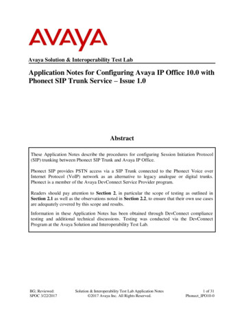
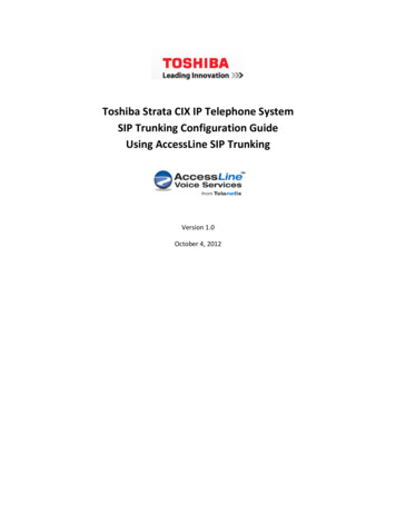
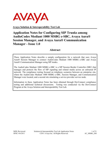
3. Reference ConfigurationFigure 1 illustrates the test configuration. The test configuration shows two sites connected via aSIP trunk across an untrusted IP network: the main enterprise site and a second site thatsimulates a service provider service node. The AudioCodes Mediant 1000 MSBG e-SBC SessionBorder Controller (SBC) is at the edge of the main site. The public side of the Mediant 1000MSBG e-SBC is connected to the untrusted network and the private side is connected to thetrusted corporate LAN.All SIP traffic between two sites flows through the Mediant 1000 MSBG e-SBC. In this manner,the Mediant 1000 MSBG e-SBC can protect the main site’s infrastructure from any SIP-basedattacks. The voice communication across the untrusted network uses SIP over TCP and RTP forthe media streams.Also connected to the LAN at the main site are: An Avaya S8300D Server running Avaya Aura Communication Manager in an AvayaG450 Media Gateway. Avaya Aura Communication Manager Messaging is alsorunning on the Avaya S8300D Server to provide voice mail functionality.A Dell PowerEdge R610 Server running Avaya Aura System Manager. SystemManager provides management functions for Session Manager.An HP ProLiant DL360 G7 Server running Avaya Aura Session Manager that providesSIP registrar and proxy server functions for SIP endpoints in the enterprise IP telephonynetwork.The Session Manager connects the Mediant 1000 MSBG e-SBC and Communication Managerusing SIP trunks. Endpoints include both SIP and non-SIP endpoints. An ISDN-PRI trunkconnects the media gateway to the PSTN.The 2nd site (shown as a cloud), simulates a service provider service node, and also comprises ofa Communication Manager, System Manager, and Session Manager, with both SIP and non-SIPendpoints.The SIP endpoints located at both sites are registered to the local Session Manager.MJH; Reviewed:SPOC 4/6/2011Solution & Interoperability Test Lab Application Notes 2011 Avaya Inc. All Rights Reserved.3 of 51AC MSBG SM
Figure 1: AudioCodes Mediant 1000 MSBG e-SBC SIP Trunking Test ConfigurationMJH; Reviewed:SPOC 4/6/2011Solution & Interoperability Test Lab Application Notes 2011 Avaya Inc. All Rights Reserved.4 of 51AC MSBG SM
4. Equipment and Software ValidatedThe following equipment and software were used for the sample configuration provided:EquipmentSoftwareAvaya Aura Communication Manager 6.0.1,Avaya S8300D Server with a Avaya G450R016x.00.1.510.1, Patch 18621Media Gateway(Avaya Aura System Platform: 6.0.2.1.5)Avaya Aura System Manager: 6.1.0 (Build No. –Dell PowerEdge R610 Server6.1.0.4.5072-6.1.4.11)(Avaya Aura System Platform: 6.0.2.1.5)Avaya Aura Session Manager 6.1.0 (Build No. –HP ProLiant DL360 G7 Server6.1.0.0.42003-6.1.0.610012)Avaya 9600 Series IP Telephones3.1. Service Pack 1 H.3232.6.4 SIPFax Machine-AudioCodes Mediant 1000 MSBG e-SBC6.2 MSBG based software:M1000 MSBG SIP F6.20A.014.003.zip Firmware load:M1000 MSBG SIP F6.20A.014.003.zip5. Configure Communication ManagerThis section describes the Communication Manager configuration at the main enterprise site tosupport the network shown in Figure 1. It is assumed the procedures necessary to support SIPand connectivity to Session Manager have been performed as described in [2] and [3]; however,some of the configuration is shown in this section and the next section as a reference.The configuration of Communication Manager was performed using the System AccessTerminal (SAT). The screens in this section display the Communication Manager configurationthat was administered and already in place prior to the start of compliance testing. After thecompletion of the configuration, a save translation command was performed to make thechanges permanent.MJH; Reviewed:SPOC 4/6/2011Solution & Interoperability Test Lab Application Notes 2011 Avaya Inc. All Rights Reserved.5 of 51AC MSBG SM
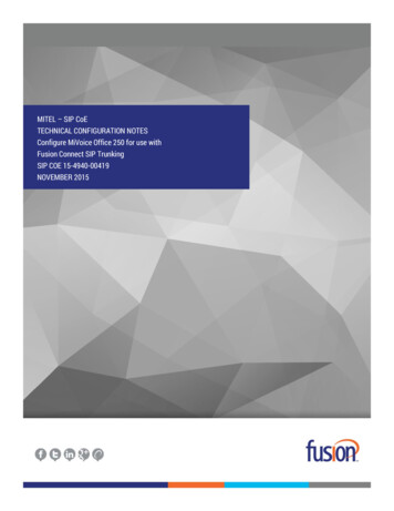
Step1.DescriptionSystem CapacitiesOn Page 2 of the display system-parameters customer-options form, verify that theMaximum Administered SIP Trunks is sufficient for the combination of trunks toAudioCodes and any other SIP trunking entities. Be aware that for each call between anon-SIP endpoint at the enterprise site and Audio Codes, one SIP trunk is used for theduration of the call. An Avaya SIP endpoint uses two SIP trunks for the duration of thecall.display system-parameters customer-optionsOPTIONAL FEATURESPageIP PORT CAPACITIESMaximum Administered H.323 Trunks:Maximum Concurrently Registered IP Stations:Maximum Administered Remote Office Trunks:Maximum Concurrently Registered Remote Office Stations:Maximum Concurrently Registered IP eCons:Max Concur Registered Unauthenticated H.323 Stations:Maximum Video Capable Stations:Maximum Video Capable IP Softphones:Maximum Administered SIP Trunks:Maximum Administered Ad-hoc Video Conferencing Ports:Maximum Number of DS1 Boards with Echo Cancellation:Maximum TN2501 VAL Boards:Maximum Media Gateway VAL Sources:Maximum TN2602 Boards with 80 VoIP Channels:Maximum TN2602 Boards with 320 VoIP Channels:Maximum Number of Expanded Meet-me Conference 005221282501281283002 of11USED223000001200000000(NOTE: You must logoff & login to effect the permission changes.)MJH; Reviewed:SPOC 4/6/2011Solution & Interoperability Test Lab Application Notes 2011 Avaya Inc. All Rights Reserved.6 of 51AC MSBG SM
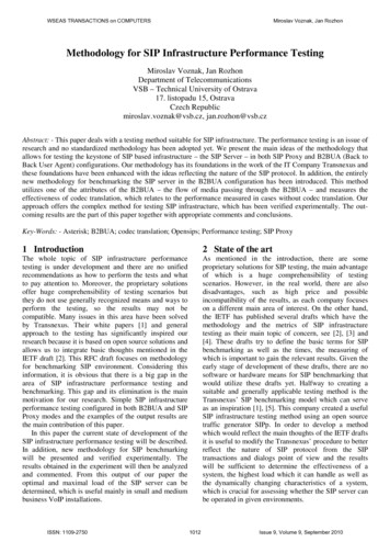
Step2.DescriptionIP network regionAll equipment at the main site were located in a single IP network region (IP networkregion 1) using the parameters described below. Use the display ip-network-regioncommand to view these settings. The example below shows the values used duringcompliance testing. Authoritative Domain: avaya.comThis field was configured to match the domain name configured on SessionManager. The domain will appear in the “From” header of SIP messagesoriginating from this IP region.Name: Any descriptive name may be used (if desired).Intra-region IP-IP Direct Audio: yesInter-region IP-IP Direct Audio: yesBy default, IP-IP direct audio (media shuffling) is enabled to allow audio traffic tobe sent directly between IP endpoints without using media resources in the AvayaMedia Gateway. Shuffling can be further restricted at the trunk level on theSignaling Group form.Codec Set: 1The codec set contains the list of codecs available for calls within this IP networkregion.display ip-network-region 1Page1 of20IP NETWORK REGIONRegion: 1Location:Authoritative Domain: avaya.comName:MEDIA PARAMETERSIntra-region IP-IP Direct Audio: yesCodec Set: 1Inter-region IP-IP Direct Audio: yesUDP Port Min: 2048IP Audio Hairpinning? nUDP Port Max: 3329DIFFSERV/TOS PARAMETERSCall Control PHB Value: 46Audio PHB Value: 46Video PHB Value: 26802.1P/Q PARAMETERSCall Control 802.1p Priority: 6Audio 802.1p Priority: 6Video 802.1p Priority: 5AUDIO RESOURCE RESERVATION PARAMETERSH.323 IP ENDPOINTSRSVP Enabled? nH.323 Link Bounce Recovery? yIdle Traffic Interval (sec): 20Keep-Alive Interval (sec): 5Keep-Alive Count: 5MJH; Reviewed:SPOC 4/6/2011Solution & Interoperability Test Lab Application Notes 2011 Avaya Inc. All Rights Reserved.7 of 51AC MSBG SM
Step3.DescriptionCodecsIP codec set 1 was used during compliance testing. Multiple codecs were listed inpriority order to allow the codec used by a specific call to be negotiated during callestablishment. The example below shows the values used during compliance testing.It should be noted that when testing the use of each individual codec, only the singlecodec under test was included in the list.display ip-codec-set 1Page1 of2IP Codec SetCodec Set: 1AudioCodec1: G.711MU2: G.729AB3:4:5:6:7:4.SilenceSuppressionnnFramesPer Pkt22PacketSize(ms)2020Node NamesUse the change node-names ip command to create a node name for the IP address ofSession Manager. Enter a descriptive name in the Name column and the IP addressassigned to Session Manager in the IP address column.change node-names ipPage1 of2IP NODE NAMESNameCM 20 40SM 20 31SM 21 31defaultmsgserverprocrprocr6MJH; Reviewed:SPOC 4/6/2011IP 64.21.4110.64.21.41::Solution & Interoperability Test Lab Application Notes 2011 Avaya Inc. All Rights Reserved.8 of 51AC MSBG SM
Step5.DescriptionSignaling GroupSignaling group 1 was used for the signaling group associated with the SIP trunk groupbetween Communication Manager and Session Manager. Signaling group 1 wasconfigured using the parameters highlighted below. Near-end Node Name: procr This node name maps to the IP address of the AvayaS8300D Server. Node names are defined using the change node-names ipcommand. Far-end Node Name: SM 21 31 This node name maps to the IP address ofSession Manager. Far-end Network Region: 1 This defines the IP network region which containsSession Manager. Far-end Domain: avaya.com This domain is sent in the “To” header of SIPmessages of calls using this signaling group. Direct IP-IP Audio Connections: y This field must be set to y to enable mediashuffling on the SIP trunk.display signaling-group 1SIGNALING GROUPGroup Number: 1Group Type: sipIMS Enabled? nTransport Method: tlsQ-SIP? nIP Video? nPeer Detection Enabled? y Peer Server: SMNear-end Node Name: procrNear-end Listen Port: 5061SIP Enabled LSP? nEnforce SIPS URI for SRTP? yFar-end Node Name: SM 21 31Far-end Listen Port: 5061Far-end Network Region: 1Far-end Domain: avaya.comIncoming Dialog Loopbacks: eliminateDTMF over IP: rtp-payloadSession Establishment Timer(min): 3Enable Layer 3 Test? yH.323 Station Outgoing Direct Media? nMJH; Reviewed:SPOC 4/6/2011Bypass If IP Threshold Exceeded?RFC 3389 Comfort Noise?Direct IP-IP Audio Connections?IP Audio Hairpinning?Initial IP-IP Direct Media?Alternate Route Timer(sec):Solution & Interoperability Test Lab Application Notes 2011 Avaya Inc. All Rights Reserved.nnynn69 of 51AC MSBG SM
Step6.DescriptionTrunk GroupTrunk group 1 was used for the SIP trunk group between Communication Manager andSession Manager. Trunk group 1 was configured using the parameters highlightedbelow. Group Type: sip This field sets the type of the trunk group. TAC: 101 Enter an valid value consistent with the Communication Manager dialplan Member Assignment Method: auto Set to Auto. Signaling Group: 1 This field is set to the signaling group shown in the previousstep. Number of Members: 10 This field represents the number of trunk groupmembers in the SIP trunk group. It determines how many simultaneous SIP callscan be supported by the configuration. Each SIP call between two SIP endpoints(whether internal or external) requires two SIP trunks for the duration of the call.Thus, a call from a SIP telephone to another SIP telephone will use two SIP trunks.A call between a non-SIP telephone and a SIP telephone will only use one trunk.display trunk-group 1Page1 of21TRUNK GROUPGroup Number:Group Name:Direction:Dial Access?Queue Length:Service Type:MJH; Reviewed:SPOC 4/6/20111to SM 21 31two-wayn0tieGroup Type: sipCDR Reports: yCOR: 1TN: 1TAC: 101Outgoing Display? nNight Service:Auth Code? nMember Assignment Method: autoSignaling Group: 1Number of Members: 10Solution & Interoperability Test Lab Application Notes 2011 Avaya Inc. All Rights Reserved.10 of 51AC MSBG SM
StepDescriptionTrunk Group – continuedOn Page 3: The Numbering Format field was set to unk-pvt. This field specifies the formatof the calling party number sent to the far-end. The default values may be retained for the other fields.display trunk-group 1TRUNK FEATURESACA Assignment? nPage3 of21Measured: noneMaintenance Tests? yNumbering Format: unk-pvtUUI Treatment: service-providerReplace Restricted Numbers? nReplace Unavailable Numbers? nModify Tandem Calling Number: noShow ANSWERED BY on Display? y7.Private NumberingPrivate Numbering defines the calling party number to be sent to the far-end. In theexample shown below, all calls originating from a 5-digit extension beginning with 5and routed across any trunk group will be sent as a 5 digit calling number. The callingparty number is sent to the far-end in the SIP “From” header.display private-numbering 0NUMBERING - PRIVATE FORMATExt ExtLen Code5 5MJH; Reviewed:SPOC 4/6/2011TrkGrp(s)PrivatePrefixPage1 of2TotalLen5Total Administered: 1Maximum Entries: 540Solution & Interoperability Test Lab Application Notes 2011 Avaya Inc. All Rights Reserved.11 of 51AC MSBG SM
Step8.DescriptionAutomatic Alternate RoutingAutomatic Alternate Routing (AAR) was used to route calls to Session Manager. Inthe example shown, dialed numbers that begin with 3 and are 5 digits long use routepattern 1. Route pattern 1 routes calls to the trunk group defined in Step 6.display aar analysis 3PageAAR DIGIT ANALYSIS TABLELocation: allDialedStringTotalMin llTypeaaraarunkuunkuaarNodeNum1 of2Percent Full: 1ANIReqdnnnnnRoute PatternRoute pattern 1 was used for calls destined for the 2nd site through Session Managerand the Mediant 1000 MSBG e-SBC. Route pattern 1 was configured using theparameters highlighted below. Pattern Name: Any descriptive name. Grp No: 1 This field is set to the trunk group number defined in Step 6. FRL: 0 This field sets the Facility Restriction Level of the trunk. It must be set toan appropriate level to allow authorized users to access the trunk. The level of 0 isthe least restrictive.display route-pattern 1PagePattern Number: 1Pattern Name: to SM 21 31SCCAN? nSecure SIP? nGrp FRL NPA Pfx Hop Toll No. InsertedNoMrk Lmt List Del DigitsDgts1: 1002:3:4:5:6:1:2:3:4:5:6:BCC VALUE TSC CA-TSC0 1 2 M 4 WRequestITC BCIE Service/Feature PARMyyyyyyrestrestrestrestrestrestMJH; Reviewed:SPOC 4/6/2011yyyyyyyyyyyyyyyyyyyyyyyynnnnnnnnnnnn1 . Numbering LARDgts FormatSubaddresslev0-pvt nonenonenonenonenonenoneSolution & Interoperability Test Lab Application Notes 2011 Avaya Inc. All Rights Reserved.12 of 51AC MSBG SM
6. Configure Session ManagerThis section provides the procedures for configuring Session Manager as provisioned in thereference configuration. All provisioning for Session Manager is performed via the SystemManager web interface.The following sections assume that Session Manager and System Manager have been installedand that network connectivity exists between the two platforms.The Session Manager server contains an SM-100 security module that provides the networkinterface for all inbound and outbound SIP signaling and media transport to all provisioned SIPentities. During compliance testing, the IP address assigned to the SM-100 interface is10.64.21.31 as specified in Figure 1. The Session Manager server also has a separate networkinterface used for connectivity to System Manager for provisioning Session Manager. The IPaddress assigned to the Session Manager management interface is 10.64.21.30. The SM-100interface and the management interface were both connected to the same IP network. If desired,the SM-100 interface can be configured to use a different network than the managementinterface.The procedures described in this section include configurations in the following areas: SIP domainLogical/physical Locations that can be occupied by SIP EntitiesSIP Entities corresponding to the SIP telephony systems (including CommunicationManager and Session Border Controller) and Session Manager itselfEntity Links which define the SIP trunk parameters used by Session Manager whenrouting calls to/from SIP EntitiesTime Ranges during which routing policies are activeRouting Policies which control call routing between the SIP EntitiesDial Patterns which govern to which SIP Entity a call is routedMJH; Reviewed:SPOC 4/6/2011Solution & Interoperability Test Lab Application Notes 2011 Avaya Inc. All Rights Reserved.13 of 51AC MSBG SM
1.LoginAccess the Session Manager administration web interface by enteringhttps:// ip-addr /network-login/ as the URL in an Internet browser, where ip-addr is the IP address of the System Manager server.Log in with the appropriate credentials. The main page for the administrative interfaceis shown below.MJH; Reviewed:SPOC 4/6/2011Solution & Interoperability Test Lab Application Notes 2011 Avaya Inc. All Rights Reserved.14 of 51AC MSBG SM
2.Add SIP DomainThe Routing menu contains all the configuration tasks listed at the beginning of thissection.During compliance testing, one SIP Domain was configured on each Session Managersince all SIP entities were located within the same authoritative domain.Navigate to Routing Domains, and click the New button (not shown) to add the SIPdomain with Name: avaya.com (as set in Section 5, Step 2) Notes: Optional descriptive text.Click Commit to save the configuration.MJH; Reviewed:SPOC 4/6/2011Solution & Interoperability Test Lab Application Notes 2011 Avaya Inc. All Rights Reserved.15 of 51AC MSBG SM
3.Add LocationLocations identify logical and/or physical locations where SIP entities reside. Only oneLocation was configured at each site for compliance testing.Navigate to Routing Locations and click the New button (not shown) to add theLocation.Under General: Name: A descriptive name. Notes: Optional descriptive text.Under Location Pattern, click the Add button to add a new line: IP Address Pattern: 10.64.21.* Notes: Optional descriptive text.Click Commit to save the configuration.MJH; Reviewed:SPOC 4/6/2011Solution & Interoperability Test Lab Application Notes 2011 Avaya Inc. All Rights Reserved.16 of 51AC MSBG SM
4.Add SIP EntitiesA SIP Entity must be added for Session Manager and for each SIP-based telephonysystem supported by it using SIP trunks. During compliance testing, a SIP Entity wasadded for the Session Manager, Communication Manager, and the AudioCodesMediant 1000 MSBG e-SBC.Navigate to Routing SIP Entities, and click the New button (not shown) to add aSIP Entity. The configuration details for the SIP Entity defined for Session Managerare as follows:Under General: Name: A descriptive name. FQDN or IP Address: 10.64.21.31 as specified in Figure 1. This is the IPaddress assigned to the SM-100 security module installed in the SessionManager. Type: select Session Manager.Under Port, click Add, then edit the fields in the resulting new row as shown below: Port: 5060. This is the port number on which the system listens for SIPrequests. Protocol: UDP. UDP was used between Session Manager and AudioCodesduring compliance testing. These steps were repeated to add Port 5061 andProtocol TLS for communication between Session Manager andCommunication Manager. Default Domain: Select the SIP Domain created in Step 2.Default settings can be used for the remaining fields. Click Commit to save the SIPEntity definition.MJH; Reviewed:SPOC 4/6/2011Solution & Interoperability Test Lab Application Notes 2011 Avaya Inc. All Rights Reserved.17 of 51AC MSBG SM
Add SIP Entities (continued) – Session ManagerThe screens below show the SIP Entity configuration details for the Session Manager.MJH; Reviewed:SPOC 4/6/2011Solution & Interoperability Test Lab Application Notes 2011 Avaya Inc. All Rights Reserved.18 of 51AC MSBG SM
Add SIP Entities (continued) – Communication ManagerThe screen below shows the SIP Entity configuration details for the CommunicationManager. Note the CM selection for Type.MJH; Reviewed:SPOC 4/6/2011Solution & Interoperability Test Lab Application Notes 2011 Avaya Inc. All Rights Reserved.19 of 51AC MSBG SM
Add SIP Entities (continued) – AudioCodes Mediant 1000 MSBG e-SBCThe screen below shows the SIP Entity configuration details for the AudioCodesMediant 1000 MSBG e-SBC. Note the Other selection for Type.MJH; Reviewed:SPOC 4/6/2011Solution & Interoperability Test Lab Application Notes 2011 Avaya Inc. All Rights Reserved.20 of 51AC MSBG SM
5.Add Entity LinksA SIP trunk between Session Manager and a telephony system is described by anEntity link. Two Entity Links were created: one between Session Manager andCommunication Manger; the other between Session Manager and AudioCodes Mediant1000 MSBG e-SBC.Navigate to Routing Entity Links, and click the New button (not shown) to add anew Entity Link. The screen below shows the configuration details for the Entity Linkconnecting Session Manager to Communication Manager. Name: A descriptive name.SIP Entity 1: Select the Session Manager SIP Entity.Port: 5061. This is the port number to which the other system sends SIPrequests. SIP Entity 2: Select the Communication Manager SIP Entity. Port: 5061. This is the port number on which the other system receives SIPrequests. Trusted: Check this box. Protocol: Select TLS as the transport protocol. Notes: Optional descriptive text.Click Commit to save the configuration.MJH; Reviewed:SPOC 4/6/2011Solution & Interoperability Test Lab Application Notes 2011 Avaya Inc. All Rights Reserved.21 of 51AC MSBG SM
Add Entity Links (continued)The Entity Link for connecting Session Manager to AudioCodes Mediant 1000 MSBGe-SBC was similarly defined as shown in the screen below, using the UDP protocoland port 5060.MJH; Reviewed:SPOC 4/6/2011Solution & Interoperability Test Lab Application Notes 2011 Avaya Inc. All Rights Reserved.22 of 51AC MSBG SM
6.Add Time RangesBefore adding routing policies (configured in next step), time ranges must be definedduring which the policies will be active. One Time Range was defined that wouldallow routing to occur at anytime.Navigate to Routing Time Ranges, and click the New button to add a new TimeRange: Name: A descriptive name.Mo through Su: Check the box under each of these headings.Start Time: Enter 00:00.End Time: Enter 23:59.Click Commit to save this time range. The screen below shows the configured TimeRange.MJH; Reviewed:SPOC 4/6/2011Solution & Interoperability Test Lab Application Notes 2011 Avaya Inc. All Rights Reserved.23 of 51AC MSBG SM
7.Add Routing PoliciesRouting policies describe the conditions under which calls will be routed to the SIPEntities connected to the Session Manager. Two routing policies were added – one forrouting calls to Communication Manager, and the other for routing calls toAudioCodes Mediant 1000 MSBG e-SBC.Navigate to Routing Routing Policies, and click the New button (not shown) to adda new Routing Policy.Under General: Name: A descriptive name. Notes: Optional descriptive text.Under SIP Entity as DestinationClick Select to select the appropriate SIP Entity to which the routing policy applies(not shown).Under Time of DayClick Add to select the Time Range configured in the previous step (not shown).Default settings can be used for the remaining fields. Click Commit to save theconfiguration.MJH; Reviewed:SPOC 4/6/2011Solution & Interoperability Test Lab Application Notes 2011 Avaya Inc. All Rights Reserved.24 of 51AC MSBG SM
Add Routing Policies (continued)The screens below show the configuration details for the two Routing Policies usedduring compliance testing.MJH; Reviewed:SPOC 4/6/2011Solution & Interoperability Test Lab Application Notes 2011 Avaya Inc. All Rights Reserved.25 of 51AC MSBG SM
8.Add Dial PatternsDial Patterns define digit strings to be matched against dialed numbers for directingcalls to the appropriate SIP Entities. 5-digit extensions beginning with “5” resided onCommunication Manager at the main enterprise site. 5-digit extensions beginning with“3” should were routed to AudioCodes Mediant 1000 MSBG e-SBC for onwardrouting to the 2nd site. Therefore two Dial Patterns were created accordingly.Navigate to Routing Dial Patterns, click the New button (not shown) to add a newDial Pattern.Under General: Pattern: Dialed number or prefix. Min: Minimum length of dialed number. Max: Maximum length of dialed number. SIP Domain: Select the SIP Domain created in Step 2 (or select –ALL– to beless restrictive). Notes: Optional descriptive text.Under Originating Locations and Routing PoliciesClick Add to select the appropriate originating Location and Routing Policy from thelist (not shown).Under Time of DayClick Add to select the time range configured in Step 6.Default settings can be used for the remaining fields. Click Commit to save theconfiguration.MJH; Reviewed:SPOC 4/6/2011Solution & Interoperability Test Lab Application Notes 2011 Avaya Inc. All Rights Reserved.26 of 51AC MSBG SM
Add Dial Patterns (continued)The screen below shows the configuration details for the Dialed Pattern defined forrouting calls to Communication Manager at the main enterprise site.MJH; Reviewed:SPOC 4/6/2011Solution & Interoperability Test Lab Application Notes 2011 Avaya Inc. All Rights Reserved.27 of 51AC MSBG SM
Add Dial Patterns (continued)The screen below shows the configuration details for the Dialed Pattern defined forrouting calls to AudioCodes Mediant 1000 MSBG e-SBC (for onward routing to the2nd site simulating a service provider service node).MJH; Reviewed:SPOC 4/6/2011Solution & Interoperability Test Lab Application Notes 2011 Avaya Inc. All Rights Reserved.28 of 51AC MSBG SM
7. Configure AudioCodes Mediant 1000 MSBG e-SBCThis section provides the procedures for configuring the AudioCodes Mediant 1000 MSBG eSBC. It is assumed that proper knowledge of the AudioCodes MSBG e-SBC usage,configuration, support in general is understood, and the craft person has experience with theproduct platform. The following information is derived from the product manuals and isreferenced only as a general guide. Configuration of the e-SBC will vary for each specificcustomer environment; however, AudioCodes has provided screenshots (and called-out specificfields on each screen with “arrows”), to show the configuration used during compliance testing.All of the configuration shown in this section can be completed using the AudioCodes Mediant1000 MSBG e-SBC web interface. From a browser, enter the IP address of the e-SBC and log inwith the appropriate credentials.7.1. Configure Data and IP Routing Network ParametersEnsure the IP Data Routing is set properly for support of routing for each network that isintended to interwork (these details are not shown, but they can be found in the installationmanual with regards to the WAN interface setting and routing, as well as LAN side settings).Once the administration is completed for the data segment, submit, Burn to Flash, and restart thedevice. Navigate to the Maint
All SIP traffic between two sites flows through the Mediant 1000 MSBG e-SBC. In this manner, the Mediant 1000 MSBG e-SBC can protect the main site's infrastructure from any SIP-based attacks. The voice communication across the untrusted network uses SIP over TCP and RTP for the media streams. Also connected to the LAN at the main site are: