Transcription
Dissolution Workstation Software (G4974AA)Operator’s Manual
NoticesManual Part NumberWarranty79-9075 Rev CJuly 2018The material contained in this documentis provided “as is,” and is subject to beingchanged, without notice, in futureeditions. Further, to the maximum extentpermitted by applicable law, Agilentdisclaims all warranties, either express orimplied, with regard to this manual andany information contained herein,including but not limited to the impliedwarranties of merchantability and fitnessfor a particular purpose. Agilent shall notbe liable for errors or for incidental orconsequential damages in connectionwith the furnishing, use, or performanceof this document or of any informationcontained herein. Should Agilent and theuser have a separate written agreementwith warranty terms covering thematerial in this document that conflictwith these terms, the warranty terms inthe separate agreement shall control.Copyright Agilent Technologies, Inc. 2018No part of this manual may bereproduced in any form or by any means(including electronic storage and retrievalor translation into a foreign language)without prior agreement and writtenconsent from Agilent Technologies, Inc.as governed by United States andinternational copyright laws.Agilent Technologies, Inc.3501 Stevens Creek Blvd.Santa Clara, CA 95052 USATechnology LicensesThe hardware and/or software describedin this document are furnished under alicense and may be used or copied only inaccordance with the terms of suchlicense.Restricted Rights LegendU.S. Government Restricted Rights.Software and technical data rightsgranted to the federal governmentinclude only those rights customarilyprovided to end user customers. Agilentprovides this customary commerciallicense in Software and technical datapursuant to FAR 12.211 (Technical Data)and 12.212 (Computer Software) and, forthe Department of Defense, DFARS252.227-7015 (Technical Data Commercial Items) and DFARS227.7202-3 (Rights in CommercialComputer Software or ComputerSoftware Documentation).Safety NoticesCAUTIO NA CAUTION notice denotes ahazard. It calls attention to anoperating procedure, practice, orthe like that, if not correctlyperformed or adhered to, couldresult in damage to the product orloss of important data. Do notproceed beyond a CAUTIONnotice until the indicatedconditions are fully understoodand met.WARNINGA WARNING notice denotes ahazard. It calls attention to anoperating procedure, practice, orthe like that, if not correctlyperformed or adhered to, couldresult in personal injury or death.Do not proceed beyond aWARNING notice until theindicated conditions are fullyunderstood and met.
Content1Introduction72Installation and Setup9Requirements and ConfigurationPC Requirements 10Software Installation or UpgradeLocal Security Policy 11Starting Dissolution Workstation101013Starting Dissolution Workstation 13Dissolution Workstation Logon 13Adding Users to the Application 14Workstation Connections16Dissolution Apparatus / 8000 / Peristaltic Pump (Daisy-chain to PC)18Dissolution Apparatus / 850-DS (Daisy-chain to PC)19Dissolution Apparatus / 8000 / Syringe Pump (Daisy-chain to PC)20Dissolution Apparatus / 8000 / Syringe Pump / Filter Changer (Daisy-chainto PC)21Dissolution Apparatus / 8000 / Peristaltic Pump (Individual to MDS) 22Dissolution Apparatus / 850-DS (Individual to MDS) 23Dissolution Apparatus / 8000 / Syringe Pump (Individual to MDS) 24Dissolution Apparatus / 8000 / Syringe Pump / Filter Changer (Individualto MDS) 25Dissolution Apparatus / 8000 / Peristaltic Pump, Syringe Pump, or SyringePump and Filter Changer (Daisy-chain to MDS) 26Dissolution Apparatus / 850-DS (Daisy-chain to MDS) 273Operation29Log On to Dissolution WorkstationConfiguring Your System3033Dissolution Apparatus 36Fraction Collector 37Syringe Pump 38Filter Changer 39Dissolution Workstation Software (G4974AA) Operator’s Manual3
ContentCompleting the Configuration 40Copying a System Configuration 41Deleting a System Configuration 41Recovering a System Configuration 42Serial Numbers 42System Configuration Report 44Editing an Existing System ConfigurationShow Audit Trail 45Verify Integrity 46Import / Export XML File 46Diagnostics / Manual Control4548Moving the Drive Unit for Apparatus 3 / Apparatus 7Dips per Minute for Apparatus 3 / Apparatus 7 51Moving the Drive Unit for Apparatus 1 / 2 51Spindle Control for Apparatus 1 / 2 53Cannula / Manifold for Apparatus 1 / 2 53Dosage Delivery for Apparatus 1 / 2 54Water Bath Temperature 54Syringe Pump / Filter Changer 55Valve Control (8000) 58Valve Control (850-DS) 59Peristaltic Pump 60Replacement Media Pump 61Method Editor5062Creating a Method 62Copying Methods 74Deleting Methods 74Recovering a Method 75Editing an Existing Method 75Method Report 76Audit Trail 76Import / Export XML File 774Dissolution Workstation Software (G4974AA) Operator’s Manual
ContentRunning the MethodTest Reports7984Electronic SignaturesClean System8586Manual Sampling87Eject Tray 89Load Tray 89Verify Timing 89MSDE Manager: Back up / Restore Database90Backing up the Database 90Restoring the Database 91Tools 92Security (21 CFR Part 11 Compliance)96Change User 96Lock Application 96Audit Trail 97Permissions 98Dissolution Workstation Software (G4974AA) Operator’s Manual5
ContentThis page was intentionally left blank, except for this message.6Dissolution Workstation Software (G4974AA) Operator’s Manual
1IntroductionDissolution Workstation Software (G4974AA) Operator’s Manual7
1IntroductionDissolution Workstation Software (G4974AA) integrates Agilent’s dissolutionapparatus and automated sampling components, allowing you to simultaneouslycontrol up to four systems of any configuration from a desktop PC. The softwareprovides a mechanism for the user to build, edit, search, retrieve, and archive alldissolution methods and test reports from a single interface.Method parameters, instrument and accessory information, and test data arecaptured and recorded within the software. View test status information in realtime as the software progresses through the timepoints for each dissolutionsystem. As part of 21 CFR Part 11 regulations, user changes to methods andsystem configurations are version controlled and documented.Agilent’s complete line of dissolution equipment is available for use withDissolution Workstation Software. This includes Apparatus 1, 2, 3, 5, 6 and 7 andthe associated pumps and automated sampling equipment.8Dissolution Workstation Software (G4974AA) Operator’s Manual
2Installation and SetupRequirements and Configuration 10Starting Dissolution Workstation 13Workstation Connections 16Dissolution Workstation Software (G4974AA) Operator’s Manual9
2Installation and SetupRequirements and ConfigurationPC RequirementsThe software is designed to run on a PC-based platform with the followingminimum specifications: Intel Pentium G4560T minimum; Intel Core i3-6100T or better preferred 4 GB of RAM (8 GB recommended) CD-ROM optical drive or USB 2.0 port (minimum) for software installation 1 USB port (2 if used with a 280-DS) 1 RS232 serial port (9-pin) or additional USB port for USB-to-serial adapter.Digi Edgeport USB-RS232 adapter recommended for multi-systemconnections. 20 GB of free hard drive space (minimum) Keyboard, mouse, and monitor with 1280 x 960 at 16M colors (minimum) Microsoft Windows 7 or 10 (32-bit or 64-bit) operating systemSoftware Installation or UpgradeNOTE10If you are upgrading Dissolution Workstation, install the newversion, ensure your data has transferred over, and then uninstallthe previous version. See “Backing up the Database” on page 90and “Restoring the Database” on page 91 for assistance.NOTEYou must log on to the computer as an administrator to set up thesoftware and run it for the first time.NOTEIf Windows User Access Control (UAC) displays during theinstallation process, click Allow to continue installation.Dissolution Workstation Software (G4974AA) Operator’s Manual
2Installation and Setup1 Insert the Dissolution Workstation CD and access the files contained on theCD.2 Execute setup.exe and follow the on-screen prompts.NOTENOTEWhen asked if you want to install a particular application (forexample, Microsoft .Net Framework,) you are required to click Yesto install all software.On the Database Server screen, do not change the password.Local Security PolicyNOTEThe Local Security Policy conforms with 21 CFR Part 11 physicalrequirement section 11.300 b. Internal IT requirements may differfrom the settings outlined in this section. It may be necessary tocoordinate the following configurations with the domainadministrator.For 21 CFR Part 11 compliance purposes, you must ensure that the followingminimum requirements are met by your system's security policy. To configureyour system's security policies, complete the following steps:1 Click Start Run.2 Type secpol.msc and click Enter to run the Local Security Settings Manager.The Local Security Settings screen displays.Dissolution Workstation Software (G4974AA) Operator’s Manual11
2Installation and Setup3 Click Security Settings Account Policies Password Policy and set theapplicable security policy configuration.PolicySecurity SettingEnforce PasswordHistory3 passwords rememberedMaximum PasswordLength30 daysMinimum PasswordLength6 charactersPassword Must MeetComplexityRequirementsEnabled4 Click Security Settings Account Policies Account Lockout Policy.Configure the options.PolicySecurity SettingAccount lockoutduration0 minutes (infinite)Account lockoutthreshold3 invalid login attemptsReset accountlockout counter99999 minutes5 Click Security Settings Local Policies Audit Policy and set the options.12PolicySecurity SettingAudit account logoneventsSuccess, FailureAudit accountmanagementSuccess, FailureAudit login eventsSuccess, FailureAudit policy changeSuccess, FailureDissolution Workstation Software (G4974AA) Operator’s Manual
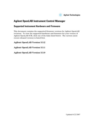
2Installation and SetupStarting Dissolution WorkstationNOTEYou must log on to the computer as an administrator to set up thesoftware and run it for the first time.Starting Dissolution Workstation1 Double-click the Dissolution Workstation icon on the Windows desktop tostart the software.2 If your system has Windows Firewall enabled, the Windows Security Alertscreen displays. Click Unblock to enable the program.Dissolution Workstation LogonFigure 1.LogonDissolution Workstation Software (G4974AA) Operator’s Manual13
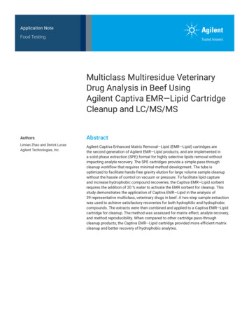
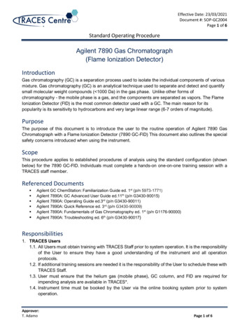
2Installation and Setup1 From the Logon screen, enter your credentials in the User ID and Passwordboxes.2 Ensure the domain selected is appropriate and click Logon to initiate thesoftware.Adding Users to the Application1 After successfully logging on to the software, click Tools Options. TheConfiguration Dialog screen displays.2 To add a user to a group, select the Security tab on the Configuration Dialogscreen.NOTETo complete this section, you must be logged on as anadministrator3 Click User Administration at the bottom of the screen. The Local Users andGroups screen displays.Figure 2.14Local Users and GroupsDissolution Workstation Software (G4974AA) Operator’s Manual
2Installation and Setup4 Double-click the Groups folder to expand the list of groups.5 Double-click all eight of the groups that begin with Vk and ensure that yourusername is logged in and is identified as a member of these groups.6 To add a user to a group, click Add. from the respective group screen. TheSelect Users, Computers, or Group screen displays.7 Enter your user identification in the empty box and click Check Names. Ensureyour user identification and domain populate the empty field. Click OK.8 Close the Local Users and Groups screen.9 Click OK to close the Configuration Dialog screen.NOTEIt may be necessary to log in again to the application to reveal thenewly granted permissions for the user.Dissolution Workstation Software (G4974AA) Operator’s Manual15
2Installation and SetupWorkstation ConnectionsThere are various ways to connect your dissolution equipment to the DissolutionWorkstation software. Each dissolution system requires at least one serial port ora serial-to-USB adapter. Cable guides are listed with each connection diagram toaid in selecting the necessary cables for your configuration.Since the software can control up to four complete dissolution systems, it isoften necessary to add additional serial ports to the PC controlling theinstruments. It is recommended to use a multiport device server (USB to serial)that is appropriate for the number of connections to be made.NOTEWhen using the multiport device server, you can connect differentdissolution systems based on port availability. This is true withdaisy-chain (instruments connected in series) or individualconnections. See “Dissolution Apparatus / 8000 / PeristalticPump, Syringe Pump, or Syringe Pump and Filter Changer(Daisy-chain to MDS)” on page 26 for an example.The following instructions refer to COM1, COM2, etc. It is acceptable tosubstitute different COM port numbers based on the physical layout of yoursystem.16Dissolution Workstation Software (G4974AA) Operator’s Manual
2Installation and SetupWorkstation ConnectionPeripheral EquipmentProceduresDaisy-chainConnection to PC8000 / peristaltic pumpsee “Dissolution Apparatus / 8000 / Peristaltic Pump (Daisy-chainto PC)” on page 18850-DSsee “Dissolution Apparatus / 850-DS (Daisy-chain to PC)” onpage 198000 / syringe pumpsee “Dissolution Apparatus / 8000 / Syringe Pump (Daisy-chain toPC)” on page 208000 / syringe pump / filterchangersee “Dissolution Apparatus / 8000 / Syringe Pump / FilterChanger (Daisy-chain to PC)” on page 218000 / peristaltic pumpsee “Dissolution Apparatus / 8000 / Peristaltic Pump (Individualto MDS)” on page 22850-DSsee “Dissolution Apparatus / 850-DS (Individual to MDS)” onpage 238000 / syringe pumpsee “Dissolution Apparatus / 8000 / Syringe Pump (Individual toMDS)” on page 248000 / syringe pump / filterchangersee “Dissolution Apparatus / 8000 / Syringe Pump / FilterChanger (Individual to MDS)” on page 258000 / peristaltic pump,syringe pump, or syringepump and filter changersee “Dissolution Apparatus / 8000 / Peristaltic Pump, SyringePump, or Syringe Pump and Filter Changer (Daisy-chain toMDS)” on page 26850-DSsee “Dissolution Apparatus / 850-DS (Daisy-chain to MDS)” onpage 27IndividualConnection toMultiport DeviceServer (MDS)Daisy-chainConnection toMultiport DeviceServer (MDS)Dissolution Workstation Software (G4974AA) Operator’s Manual17
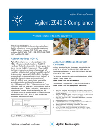
2Installation and SetupDissolution Apparatus / 8000 / Peristaltic Pump(Daisy-chain to PC)Part 1*0* supplied with pump18Dissolution Workstation Software (G4974AA) Operator’s Manual
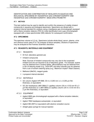
2Installation and SetupDissolution Apparatus / 850-DS (Daisy-chain to PC)Part ution Workstation Software (G4974AA) Operator’s Manual19
2Installation and SetupDissolution Apparatus / 8000 / Syringe Pump(Daisy-chain to PC)20Part 4491Dissolution Workstation Software (G4974AA) Operator’s Manual
2Installation and SetupDissolution Apparatus / 8000 / Syringe Pump / FilterChanger (Daisy-chain to PC)Part 4492Dissolution Workstation Software (G4974AA) Operator’s Manual21
2Installation and SetupDissolution Apparatus / 8000 / Peristaltic Pump(Individual to MDS)Part NumberQuantity5075-0252212-00110* supplied with pump22Dissolution Workstation Software (G4974AA) Operator’s Manual
2Installation and SetupDissolution Apparatus / 850-DS (Individual to MDS)Part NumberQuantity5075-02522Dissolution Workstation Software (G4974AA) Operator’s Manual23
2Installation and SetupDissolution Apparatus / 8000 / Syringe Pump (Individualto MDS)24Part NumberQuantity5075-025225075-04481Dissolution Workstation Software (G4974AA) Operator’s Manual
2Installation and SetupDissolution Apparatus / 8000 / Syringe Pump / FilterChanger (Individual to MDS)Part NumberQuantity5075-025225075-04482Dissolution Workstation Software (G4974AA) Operator’s Manual25
2Installation and SetupDissolution Apparatus / 8000 / Peristaltic Pump, SyringePump, or Syringe Pump and Filter Changer (Daisy-chainto MDS)26Dissolution Workstation Software (G4974AA) Operator’s Manual
2Installation and SetupDissolution Apparatus / 850-DS (Daisy-chain to MDS)Dissolution Workstation Software (G4974AA) Operator’s Manual27
2Installation and SetupThis page was intentionally left blank, except for this message.28Dissolution Workstation Software (G4974AA) Operator’s Manual
3OperationLog On to Dissolution Workstation 30Configuring Your System 33Diagnostics / Manual Control 48Method Editor 62Running the Method 79Test Reports 84Clean System 86Manual Sampling 87MSDE Manager: Back up / Restore Database 90Security (21 CFR Part 11 Compliance) 96Dissolution Workstation Software (G4974AA) Operator’s Manual29
3OperationLog On to Dissolution Workstation1 Double-click the Dissolution Workstation icon on your desktop. The Logonscreen displays.Figure 3.Logon2 Enter your user identification and password. Verify the domain is correct andclick Logon. The Dissolution Workstation screen displays.30Dissolution Workstation Software (G4974AA) Operator’s Manual
3OperationFigure 4.Dissolution WorkstationDissolution Workstation Software (G4974AA) Operator’s Manual31
3OperationThe following options are available in the navigation bar on the DissolutionWorkstation homescreen:32OptionFunctionConfigurationCreate a file for each dissolution apparatus. All relevant data includingconfiguration and component serial numbers is stored within this file.DiagnosticsVerify communication or view real-time data from the modules.EditorCreate a test method to define parameters and tolerances to be verified.Run MethodBegin a test using previously created apparatus and methods.Test ReportsSearch and retrieve previously executed tests based on various filtered criteria.Change UserLog on to the Dissolution Workstation Software as a different user.Lock ApplicationLock the Dissolution Workstation Software.Audit TrailVerify, filter, or create reports of logon information for the DissolutionWorkstation Software.PermissionsView the rights and privileges for users of the Dissolution Workstation Software.Dissolution Workstation Software (G4974AA) Operator’s Manual
3OperationConfiguring Your SystemIt is necessary to configure the components that will be used for automatedsample collection. Systems can be added, modified, and removed from thedatabase. All system configuration activity is recorded in the system audit log.The dissolution software allows the configuration of multiple systems. Amaximum of four systems can be running methods at one time.System configuration entails selecting the appropriate equipment and setting thecommunication and other physical properties of the system. Serial numbers arestored for each system to allow tracking of physical system changes.1 From the navigation bar, click Configuration. The System Configurationscreen displays.Figure 5.System ConfigurationDissolution Workstation Software (G4974AA) Operator’s Manual33
3Operation2 Click Create. The System Editor screen displays.Figure 6.34System EditorDissolution Workstation Software (G4974AA) Operator’s Manual
3Operation3 Click Next. Following is a description of the System Editor screen options:OptionSystemDescriptionSystem NameEnter a name for your system.LaboratoryEnter a laboratory name.Dissolution SetupClick the drop-down arrow on the Dissolution Setup box to select Apparatus3/7, Apparatus 1/2/5/6, or NONE.Click the drop-down arrow in the Dissolution Setup box to select PeristalticPump or Syringe Pump.If your system configuration includes an 8000 or 850-DS, click FractionCollector.If your system configuration includes a syringe pump, once Syringe Pump isselected from the drop-down menu above, the Filter Changer option becomesactive. Click Filter Changer if your system configuration includes a filterchanger (or the 850-DS includes the Filter Module).Manual SamplingTimepoint Alarm Lead Time (MM:SS) - The amount of time that the manifoldlowers prior to the sample timepoint. This allows for equilibration of thetemperature probes before vessel temperature measurements.Timepoint Duration (MM:SS) - This is the amount of time that the manifoldremains at its sampling position after the sample timepoint. The sum of theLead Time and Duration should total a minimum of 30 seconds for accuratetemperature readings.Restrict Execution To Specified WorkstationClickto display the name of the workstation or enter the name of theworkstation connected to the system. Click No Restriction to allow the systemto be run from any workstation.Note: The system must be physically connected.Change ManagementIf applicable, select the box under Change Management in order to restrict thesystem editing rights to the current user.Note: This option prevents system configuration modification by anyone otherthan the system owner or a user with VkModifyOthersSystems privilege.4 Click Next. The following sections describe the screens that display based onthe selections entered on the System Editor screen.Dissolution Workstation Software (G4974AA) Operator’s Manual35
3OperationDissolution Apparatus1 If applicable, either the BIO-DIS screen or the Dissolution Tester screendisplays. Click Next. Depending on the chosen configuration, the following is adescription of the screen options available for either Apparatus 1/2/5/6 orApparatus 3/7:Dissolution ApparatusComm AddressEnter the appropriate communication address for the dissolution apparatus.OptionsClick the appropriate dissolution apparatus options.Using the up and down arrows, indicate the number of active vessel positions.BIO-DISComm AddressEnter the appropriate communication address for the dissolution apparatus.RowsUsing the up and down arrows, indicate the number of rows.Note: This setting must match the physical configuration of the instrument.Sample ChannelsNOTE36Using the up and down arrows, indicate the number of sample channels.Note: This setting must match the physical configuration of the instrument.The communication address (PC port: instrument ID) is comprised of thephysical PC COM port (PC port) and the instrument address on the serialbus (instrument ID). For example: COM1:01.Dissolution Workstation Software (G4974AA) Operator’s Manual
3OperationFraction Collector1 If you selected Fraction Collector, the Fraction Collector screen displays. Enterthe appropriate communication address for the fraction collector. Whenconnecting to the PC, enter the com port and comm ID. Verify the comm ID onthe fraction collector is set to the same value.NOTEThe communication address (PC port: instrument ID) is comprised of thephysical PC COM port (PC port) and the instrument address on the serialbus (instrument ID). For example: COM1:01.2 Using the up and down arrows, indicate the number of channels.3 Verify the fraction collector is configured for the proper number of channels.4 Click Next.Dissolution Workstation Software (G4974AA) Operator’s Manual37
3OperationSyringe Pump1 If you selected Syringe Pump, the Syringe Pump screen displays.NOTEThere is no additional screen if you select Peristaltic Pump sinceno specific pump parameters are required.Following is a description of the Syringe Pump screen options:OptionDescriptionComm AddressEnter the appropriate communication address for the syringe pump. When connecting to thePC, enter COMx:76.Note: If you are using an 850-DS, the com port for the syringe pump has to be same as the850-DS. Do not change the comm ID of 76.Current Level (8000 only)Use the up and down arrows to indicate the motor power (current level). The recommendedsetting is 4.Calibration CountUse the up and down arrows to indicate the calibration count. This number refers to thenumber of steps the motor moves to lower the syringe for a full stroke. The default setting is19300 (19000 for the 850-DS). To optimize volume accuracy, use the Calibration Countcalculator to convert the 850-DS mL/stroke value to the appropriate Calibration Count value.This value should be adjusted (as needed) each time a volume calibration is performed on the850-DS.Plunger SpeedUse the up and down arrows to configure the syringe pump plunger to operate at a specificspeed.Note: If an 8000 is configured, steps/sec is used. If an 850-DS is equipped, ml/min is displayed.Aspiration DwellUse the up and down arrows to indicate the aspiration dwell time. This is the time (in seconds)that the syringe pauses after pulling in liquid prior to dispensing. This time may need to beincreased to maintain volume accuracy for certain types of dissolution media.Prime LossUse the up and down arrows to indicate the prime loss volume. This parameter accounts forthe volume of sample to travel from the dissolution vessel to the sample tubes or vials prior tocollection. The volume is moved through the sample lines prior to sample collection at eachsample timepoint.Syringe SizeClick the drop-down arrow and select the syringe size (10.0 mL for the 806 Syringe Pump; 1.0mL for the 850-DS).2 Click Next.3 If you selected Filter Changer, the Filter Changer screen displays.38Dissolution Workstation Software (G4974AA) Operator’s Manual
3OperationFilter Changer1 If you selected Filter Changer, the Filter Changer screen displays.Following is a description of the Filter Changer screen options:OptionDescriptionComm AddressEnter the appropriate communication address for the filter changer. When connecting to thePC, enter COMx:75.Note: If you are using an 850-DS, the com port for the filter changer has to be same as the850-DS. Do not change the comm ID of 75.2 Click Next.Dissolution Workstation Software (G4974AA) Operator’s Manual39
3OperationCompleting the Configuration1 After the final screen specific to your configuration, the Serial Numbers screendisplays (see Figure 7, “Serial Numbers,” on page 40).Figure 7.Serial Numbers2 From the drop-down menu, select the type of accessory (for example: basket,shaft, paddle, vessel) in the box that corresponds to Type.3 Enter the serial number for each individual accessory.4 Optionally, click Cert. to store the link to a Certificate of Conformance for thespecified accessory. This file may be a .pdf, .doc, or .xps file.5 Click Add to store the accessory information.6 Repeat steps 2-5 for each accessory.7 Enter the serial number for the item and click Add.8 Repeat steps 2 and 3 for each item selected under Dissolution Setup on theSystem Editor screen (see “Dissolution Setup” on page 35).40Dissolution Workstation Software (G4974AA) Operator’s Manual
3Operation9 Click Finish.10 Repeat all the sections under “Configuring Your System” on page 33 for eachadditional system.11 Close the System Configuration screen.Copying a System ConfigurationTo copy a system configuration, complete the following steps:1 From the navigation bar, click Configuration. The System Configurationscreen displays (see Figure 5, “System Configuration,” on page 33).2 Select the desired system configuration.3 Click Copy.4 Click Paste. A new system configuration displays. The description of the newsystem configuration is Copy of.5 Close the System Configuration screen.6 To edit the system configuration, see “Editing an Existing SystemConfiguration” on page 45.Deleting a System ConfigurationTo delete a system configuration, complete the following steps:1 From the navigation bar, click Configuration. The System Configurationscreen displays (see Figure 5, “System Configuration,” on page 33).2 Select the desired system configuration.3 Click Delete.4 Click Yes.5 Close the System Configuration screen.NOTEThe system configuration is never physically deleted. It is onlyremoved from the visible list of displayed configurations and maybe recovered from the database at any time.Dissolution Workstation Software (G4974AA) Operator’s Manual41
3OperationRecovering a System ConfigurationTo recover a deleted system configuration, complete the following steps:1 From the navigation bar, click Configuration Recover. The SystemConfiguration screen displays.2 Select the desired system configuration.3 Click OK.Serial NumbersTo review or add serial numbers to the system configuration, complete thefollowing steps:1 From the navigation bar, click Configuration. The System Configurationscreen displays (see Figure 5, “System Configuration,” on page 33).2 Select the desired system configuration.3 Click Serial Numbers. The Serial Number Editor screen displays (seeFigure 8, “Serial Number Editor,” on page 43).NOTE42Alternately, you can double-click the desired system configurationand double-click Next until the Serial Numbers section of theSystem Editor displays or right-click the desired systemconfiguration and select Serial Numbers. Serial numbers can beadded or deleted as a result of any of these actions.Dissolution Workstation Software (G4974AA) Operator’s Manual
3OperationFigure 8.Serial Number Editor4 From the drop-down menu, select the type of accessory (for example: basket,shaft, paddle, vessel) in the box that corresponds to Type.5 Enter the serial number for the accessory.6 Optionally, click Cert. to store the link to a Certificate of Conformance for thespecified accessory. This file may be a .pdf, .doc, or .xps file.7 Click Add to store the accessory information.8 Repeat steps 4-7 for each accessory.9 Enter the serial number for the item and click Add.10 Repeat steps 4 and 5 for each item selected under Dissolution Setup (see“Dissolution Setup” on page 35).11 Click OK. The Serial Number Editor screen closes.Dissolution Workstation Software (G4974AA) Operator’s Manual43
3OperationSystem Configuration ReportTo display a report of the system configuration, complete the following steps:1 From the naviga
Audit account logon events Success, Failure Audit account management Success, Failure Audit login events Success, Failure Audit policy change Success, Failure. 2 Installation and Setup Dissolution Workstation Software (G4974AA) Operator's Manual 13 Starting Dissolution Workstation