Transcription
INNERSHIELD ELECTRODESWelding Guide
TABLE OF CONTENTSSAFETY PRECAUTIONS .3-11INTRODUCTION .12PRODUCT ADVANTAGES.13-15RECOMMENDED EQUIPMENT .15WELDING PREPARATIONS .16-17Choose the Proper Innershield Gun .16Prepare the Work.17Optimizing Feeding.17WELDING TECHNIQUES .18-24Set the CTWD.18Set the Wire Feed Speed (WFS) .19Start the Arc.19Set the Voltage .19Travel Speed .19Loading 13-14 Lb. Coils on a 2” Spindle.20Handling Poor Fitup .21Use the Proper Drag Angle.21Use the Proper Wire Angle to Joint .21Making Vertical Up Welds .22-23Making Downhill and Vertical Down Welds .23Working with NS-3M .24OPERATING GUIDE .25-29Troubleshooting.25-26Effect of Operating Variables.26-27Welder Qualification Test.27Storing Innershield Electrode .28-29WELDING PROCEDURES .30-39OPERATING PROCEDURES .40-45INNERSHIELD GUN PARTS .46-47LINCOLN WELDING SCHOOL .48-49–2–
The serviceability of a product or structure utilizing thistype of information is and must be the sole responsibilityof the builder/user. Many variables beyond the control ofThe Lincoln Electric Company affect the results obtainedin applying this type of information. These variablesinclude, but are not limited to, welding procedure, platechemistry and temperature, weldment design, fabricationmethods and service requirements.-SAFETYWARNINGCALIFORNIA PROPOSITION 65 WARNINGSDiesel engine exhaust and some of its constituents are knownto the State of California to cause cancer, birth defects, andother reproductive harm.The Above For Diesel EnginesThe engine exhaust from this product contains chemicalsknown to the State of California to cause cancer, birth defects,or other reproductive harm.The Above For Gasoline EnginesARC WELDING CAN BE HAZARDOUS. PROTECT YOURSELF ANDOTHERS FROM POSSIBLE SERIOUS INJURY OR DEATH. KEEPCHILDREN AWAY. PACEMAKER WEARERS SHOULD CONSULT WITHTHEIR DOCTOR BEFORE OPERATING.Read and understand the following safety highlights. Foradditional safety information, it is strongly recommended thatyou purchase a copy of “Safety in Welding & Cutting - ANSIStandard Z49.1” from the American Welding Society, P.O. Box351040, Miami, Florida 33135 or CSA Standard W117.2-1974.A Free copy of “Arc Welding Safety” booklet E205 is availablefrom the Lincoln Electric Company, 22801 St. Clair Avenue,Cleveland, Ohio 44117-1199.BE SURE THAT ALL INSTALLATION, OPERATION,MAINTENANCE AND REPAIR PROCEDURES AREPERFORMED ONLY BY QUALIFIED INDIVIDUALS.Mar ‘95–3–
FOR ENGINEpowered equipment.1.a. Turn the engine off before troubleshooting and maintenancework unless the maintenance work requires it to be running.1.b. Operate engines in open, well-ventilatedareas or vent the engine exhaust fumesoutdoors.1.c. Do not add the fuel near an open flamewelding arc or when the engine is running.Stop the engine and allow it to cool beforerefueling to prevent spilled fuel fromvaporizing on contact with hot engine partsand igniting. Do not spill fuel when fillingtank. If fuel is spilled, wipe it up and do notstart engine until fumes have beeneliminated.1.d. Keep all equipment safety guards, covers and devices inposition and in good repair.Keep hands, hair, clothing andtools away from V-belts, gears, fans and all other movingparts when starting, operating or repairing equipment.1.e. In some cases it may be necessary to remove safetyguards to perform required maintenance. Removeguards only when necessary and replace them when themaintenance requiring their removal is complete.Always use the greatest care when working near movingparts.1.f. Do not put your hands near the engine fan.Do not attempt to override the governor oridler by pushing on the throttle control rodswhile the engine is running.1.g. To prevent accidentally starting gasoline engines whileturning the engine or welding generator during maintenancework, disconnect the spark plug wires, distributor cap ormagneto wire as appropriate.1.h. To avoid scalding, do not remove theradiator pressure cap when the engine ishot.–4–
ELECTRIC ANDMAGNETIC FIELDSmay be dangerous2.a. Electric current flowing through any conductor causeslocalized Electric and Magnetic Fields (EMF). Weldingcurrent creates EMF fields around welding cables andwelding machines2.b. EMF fields may interfere with some pacemakers, andwelders having a pacemaker should consult their physicianbefore welding.2.c. Exposure to EMF fields in welding may have other healtheffects which are now not known.2.d. All welders should use the following procedures in order tominimize exposure to EMF fields from the welding circuit:2.d.1. Route the electrode and work cables together - Securethem with tape when possible.2.d.2. Never coil the electrode lead around your body.2.d.3. Do not place your body between the electrode andwork cables. If the electrode cable is on your rightside, the work cable should also be on your right side.2.d.4. Connect the work cable to the workpiece as close aspossible to the area being welded.2.d.5. Do not work next to welding power source.ELECTRIC SHOCK cankill.3.a. The electrode and work (or ground) circuitsare electrically “hot” when the welder is on.Do not touch these “hot” parts with your bareskin or wet clothing. Wear dry, hole-freegloves to insulate hands.3.b. Insulate yourself from work and ground using dry insulation.Make certain the insulation is large enough to cover your fullarea of physical contact with work and ground.In addition to the normal safety precautions, if weldingmust be performed under electrically hazardousconditions (in damp locations or while wearing wetclothing; on metal structures such as floors, gratings orscaffolds; when in cramped positions such as sitting,(Cont’d on page 5)–5–
ELECTRIC SHOCK can kill.(Cont’d)kneeling or lying, if there is a high risk of unavoidable oraccidental contact with the workpiece or ground) usethe following equipment: Semiautomatic DC Constant Voltage (Wire) Welder. DC Manual (Stick) Welder. AC Welder with Reduced Voltage Control.3.c. In semiautomatic or automatic wire welding, the electrode,electrode reel, welding head, nozzle or semiautomaticwelding gun are also electrically “hot”.3.d. Always be sure the work cable makes a good electricalconnection with the metal being welded. The connectionshould be as close as possible to the area being welded.3.e. Ground the work or metal to be welded to a good electrical(earth) ground.3.f. Maintain the electrode holder, work clamp, welding cable andwelding machine in good, safe operating condition. Replacedamaged insulation.3.g. Never dip the electrode in water for cooling.3.h. Never simultaneously touch electrically “hot” parts ofelectrode holders connected to two welders because voltagebetween the two can be the total of the open circuit voltageof both welders.3.i. When working above floor level, use a safety belt to protectyourself from a fall should you get a shock.3.j. Also see Items 6.c. and 8.ARC RAYS can burn.4.a. Use a shield with the proper filter and coverplates to protect your eyes from sparks andthe rays of the arc when welding or observingopen arc welding. Headshield and filter lensshould conform to ANSI Z87. I standards.4.b. Use suitable clothing made from durable flame-resistantmaterial to protect your skin and that of your helpers fromthe arc rays.4.c. Protect other nearby personnel with suitable, non-flammablescreening and/or warn them not to watch the arc nor exposethemselves to the arc rays or to hot spatter or metal.–6–
FUMES AND GASEScan be dangerous.5.a. Welding may produce fumes and gaseshazardous to health. Avoid breathing thesefumes and gases.When welding, keepyour head out of the fume. Use enoughventilation and/or exhaust at the arc to keepfumes and gases away from the breathing zone. Whenwelding with electrodes which require specialventilation such as stainless or hard facing (seeinstructions on container or MSDS) or on lead orcadmium plated steel and other metals or coatingswhich produce highly toxic fumes, keep exposure aslow as possible and below Threshold Limit Values (TLV)using local exhaust or mechanical ventilation. Inconfined spaces or in some circumstances, outdoors, arespirator may be required. Additional precautions arealso required when welding on galvanized steel.5.b. Do not weld in locations near chlorinated hydrocarbon vaporscoming from degreasing, cleaning or spraying operations.The heat and rays of the arc can react with solvent vapors toform phosgene, a highly toxic gas, and other irritatingproducts.5.c. Shielding gases used for arc welding can displace air andcause injury or death. Always use enough ventilation,especially in confined areas, to insure breathing air is safe.5.d. Read and understand the manufacturer’s instructions for thisequipment and the consumables to be used, including thematerial safety data sheet (MSDS) and follow youremployer’s safety practices. MSDS forms are available fromyour welding distributor or from the manufacturer.5.e. Also see item 1.b.WELDING SPARKS cancause fire or explosion.6.a. Remove fire hazards from the welding area.If this is not possible, cover them to preventthe welding sparks from starting a fire.Remember that welding sparks and hotmaterials from welding can easily go through small cracksand openings to adjacent areas. Avoid welding nearhydraulic lines. Have a fire extinguisher readily available.6.b. Where compressed gases are to be used at the job site,special precautions should be used to prevent hazardoussituations. Refer to “Safety in Welding and Cutting” (ANSIStandard Z49.1) and the operating information for theequipment being used.–7–
WELDING SPARKS can cause fire(Cont’d)or explosion.6.c. When not welding, make certain no part of the electrodecircuit is touching the work or ground. Accidental contactcan cause overheating and create a fire hazard.6.d. Do not heat, cut or weld tanks, drums or containers until theproper steps have been taken to insure that such procedureswill not cause flammable or toxic vapors from substancesinside. They can cause an explosion even though they havebeen “cleaned”. For information, purchase “RecommendedSafe Practices for the Preparation for Welding and Cutting ofContainers and Piping That Have Held HazardousSubstances”, AWS F4.1 from the American Welding Society(see address above).6.e. Vent hollow castings or containers before heating, cutting orwelding. They may explode.6.f. Sparks and spatter are thrown from the welding arc. Wear oilfree protective garments such as leather gloves, heavy shirt,cuffless trousers, high shoes and a cap over your hair. Wearear plugs when welding out of position or in confined places.Always wear safety glasses with side shields when in awelding area.6.g. Connect the work cable to the work as close to the weldingarea as practical. Work cables connected to the buildingframework or other locations away from the welding areaincrease the possibility of the welding current passingthrough lifting chains, crane cables or other alternatecircuits. This can create fire hazards or overheat liftingchains or cables until they fail.6.h. Also see item 1.c.CYLINDER may explodeif damaged.7.a. Use only compressed gas cylinderscontaining the correct shielding gas for theprocess used and properly operatingregulators designed for the gas andpressure used. All hoses, fittings, etc. should be suitable forthe application and maintained in good condition.7.b. Always keep cylinders in an upright position securelychained to an undercarriage or fixed support.7.c. Cylinders should be located: Away from areas where they may be struck or subjected tophysical damage. A safe distance from arc welding or cutting operations andany other source of heat, sparks, or flame.–8–
CYLINDER may explode ifdamaged.(Cont’d)7.d. Never allow the electrode, electrode holder or any otherelectrically “hot” parts to touch a cylinder.7.e. Keep your head and face away from the cylinder valve outletwhen opening the cylinder valve.7.f. Valve protection caps should always be in place and handtight except when the cylinder is in use or connected foruse.7.g. Read and follow the instructions on compressed gascylinders, associated equipment, and CGA publication P-l,“Precautions for Safe Handling of Compressed Gases inCylinders,” available from the Compressed Gas Association1235 Jefferson Davis Highway, Arlington, VA 22202.FOR ELECTRICALLYpowered equipment.8.a. Turn off input power using the disconnectswitch at the fuse box before working onthe equipment.8.b. Install equipment in accordance with the U.S. NationalElectrical Code, all local codes and the manufacturer’srecommendations.8.c. Ground the equipment in accordance with the U.S. NationalElectrical Code and the manufacturer’s recommendations.PRÉCAUTIONS DE SÛRETÉPour votre propre protection lire et observer toutes les instructionset les précautions de sûreté specifiques qui parraissent dans cemanuel aussi bien que les précautions de sûreté généralessuivantes:Sûreté Pour Soudage A L’Arc1. Protegez-vous contre la secousse électrique:a. Les circuits à l’électrode et à la piéce sont sous tensionquand la machine à souder est en marche. Eviter toujourstout contact entre les parties sous tension et la peau nueou les vétements mouillés. Porter des gants secs et sanstrous pour isoler les mains.–9–
b. Faire trés attention de bien s’isoler de la masse quand onsoude dans des endroits humides, ou sur un planchermetallique ou des grilles metalliques, principalement dansles positions assis ou couché pour lesquelles une grandepartie du corps peut être en contact avec la masse.c. Maintenir le porte-électrode, la pince de masse, le câble desoudage et la machine à souder en bon et sûr étatdefonctionnement.d. Ne jamais plonger le porte-électrode dans l’eau pour lerefroidir.e. Ne jamais toucher simultanément les parties sous tensiondes porte-électrodes connectés à deux machines à souderparce que la tension entre les deux pinces peut être le totalde la tension à vide des deux machines.f. Si on utilise la machine à souder comme une source decourant pour soudage semi-automatique, ces precautionspour le porte-électrode s’applicuent aussi au pistolet desoudage.2. Dans le cas de travail au dessus du niveau du sol, se protégercontre les chutes dans le cas ou on recoit un choc. Ne jamaisenrouler le câble-électrode autour de n’importe quelle partie ducorps.3. Un coup d’arc peut être plus sévère qu’un coup de soliel, donc:a. Utiliser un bon masque avec un verre filtrant approprié ainsiqu’un verre blanc afin de se protéger les yeux durayonnement de l’arc et des projections quand on soude ouquand on regarde l’arc.b. Porter des vêtements convenables afin de protéger la peaude soudeur et des aides contre le rayonnement de l‘arc.c. Protéger l’autre personnel travaillant à proximité au soudageà l’aide d’écrans appropriés et non-inflammables.4. Des gouttes de laitier en fusion sont émises de l’arc de soudage.Se protéger avec des vêtements de protection libres de l’huile,tels que les gants en cuir, chemise épaisse, pantalons sansrevers, et chaussures montantes.5. Toujours porter des lunettes de sécurité dans la zone desoudage. Utiliser des lunettes avec écrans lateraux dans leszones où l’on pique le laitier.6. Eloigner les matériaux inflammables ou les recouvrir afin deprévenir tout risque d’incendie dû aux étincelles.– 10 –
7. Quand on ne soude pas, poser la pince à une endroit isolé dela masse. Un court-circuit accidental peut provoquer unéchauffement et un risque d’incendie.8. S’assurer que la masse est connectée le plus prés possiblede la zone de travail qu’il est pratique de le faire. Si on placela masse sur la charpente de la construction ou d’autresendroits éloignés de la zone de travail, on augmente le risquede voir passer le courant de soudage par les chaines delevage, câbles de grue, ou autres circuits. Cela peutprovoquer des risques d’incendie ou d’echauffement deschaines et des câbles jusqu’à ce qu’ils se rompent.9. Assurer une ventilation suffisante dans la zone de soudage.Ceci est particuliérement important pour le soudage de tôlesgalvanisées plombées, ou cadmiées ou tout autre métal quiproduit des fumeés toxiques.10. Ne pas souder en présence de vapeurs de chlore provenantd’opérations de dégraissage, nettoyage ou pistolage. Lachaleur ou les rayons de l’arc peuvent réagir avec les vapeursdu solvant pour produire du phosgéne (gas fortement toxique)ou autres produits irritants.11. Pour obtenir de plus amples renseignements sur la sûreté,voir le code “Code for safety in welding and cutting” CSAStandard W 117.2-1974.PRÉCAUTIONS DE SÛRETÉ POURLES MACHINES À SOUDER ÀTRANSFORMATEUR ET ÀREDRESSEUR1. Relier à la terre le chassis du poste conformement au code del’électricité et aux recommendations du fabricant. Le dispositifde montage ou la piece à souder doit être branché à unebonne mise à la terre.2. Autant que possible, I’installation et l’entretien du poste seronteffectués par un électricien qualifié.3. Avant de faires des travaux à l’interieur de poste, ladebrancher à l’interrupteur à la boite de fusibles.4. Garder tous les couvercles et dispositifs de sûreté à leurplace.– 11 –
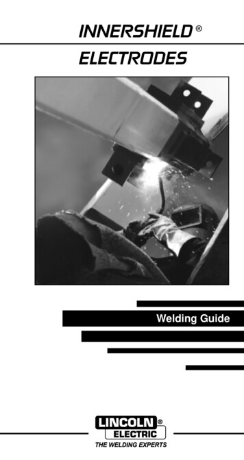
INTRODUCTIONINNERSHIELD Innershield is an arc welding process that uses a continuously fedwire to supply filler metal to the arc. The wire is not solid, but istubular. Agents necessary to shield the arc from the surroundingatmosphere are placed inside the tube. No additional shielding isrequired. Innershield was originally used as a replacement for stickwelding. Innershield can provide higher productivity and enhancequality when compared to stick welding. It offers increased arc-ontime due to the continuous nature of the process. There are alsofewer starts and stops, which are frequent sources for defects.Although the Innershield process has been displaced in manyareas by gas-shielded processes, Innershield continues to be animportant process for steel fabrication in many markets.Innershield is the primary means for structural steel buildingerection in the United States. In any shop or shipyard where windis a problem, Innershield can be a viable solution. Pipelinefabrication is often done with Innershield because it is doneoutdoors and shielding gas is sometimes difficult to get to theselocations.Lincoln Electric, the originator of the Innershield process, makesInnershield wire in a proprietary manner. The manufacturingprocesses that Lincoln Electric uses has specific benefits that youcan see in every pound of wire you use. The Innershield wiresLincoln Electric produces are very stiff and have excellent columnstrength. This allows for excellent feedability. Lincoln Electric alsofills the wire in a proprietary manner. This step ensures that you getthe right amount of fill in every inch of wire. Lincoln Electric is theworldwide leader in Innershield. You can see that when you useour products, meet with our sales reps, or call the factory forsupport.Current carryingcontact tipInsulated GuideArcWire core consists ofpowdered metal, vapor(or gas) forming materials,deoxidizers and scavengers.Molten slagSolidifiedslagArc shield composed ofvaporized and slag formingcompounds protects metaltransferring through arc.Metaldropletscovered witha thin slagcoating,formingmolten puddle.SolidifiedweldmetalMoltenweld metal– 12 –
PRODUCT ADVANTAGESINNERSHIELD FEATURES Can be used in wind speeds of up to 30 mph without losingmechanical properties. Gas bottles are unnecessary. Stiff wire with high column strength.BENEFITS OVER GAS-SHIELDEDPROCESSES Innershield does not require gas shielding. No external shielding eliminates gas cost. No shielding gas means no cylinder handling, changeout,and rental saving time and money. No shielding gas means simpler guns and feeders forlower maintenance costs. No shielding gas means no tenting to keep wind awaysaving labor costs. Innershield Wires are stiff. Stiff wire is excellent for feedability. Stiff wire allows for longer guns to be used, saving labor.costs moving feeders and welders. Stiff wire allows the welder to break off the wire withoutclippers.BENEFITS OVER STICK WELDING Innershield is a continuous process. This means less starts and stops, saving money andincreasing quality. This allows the welder to spend more time welding, notchanging rods, decreasing labor costs. Innershield has higher deposition efficiency. Innershield does not produce “stubs” like the stick process.Stubs are materials you purchase and then throw away.– 13 –
PRODUCT LIMITATIONSSEISMIC APPLICATIONS:Constant voltage (CV) power sources are recommended for usewith all Innershield electrodes.NR-211-MP THICKNESS RESTRICTIONS:Wire DiameterMax. Plate Thickness.035”, .045” (0.9, 1.2mm).068”, 5/64”, 3/32”(1.7, 2.0, 2.4mm)5/16” (7.9mm)1/2” (12.7mm)NR-212 is designed to be used on plate up to 3/4”(19.1mm) thick.SINGLE PASS LIMITATIONSCertain FCAW-S electrodes are limited to single pass applications.These include, but are not limited to NR-1, NR-5, NR-131 andNR-152.APPLICATION INFORMATIONSEISMIC STRUCTURAL WELDING APPLICATIONSThe electrodes below have been tested in accordance with FEMA353 - Recommended Specifications and Quality AssuranceGuidelines for Steel Moment-Frame Construction for SeismicApplications. FEMA 353 test certificates are available uponrequest. These certificates contain mechanical test results at lowand high heat input levels and diffusible hydrogen classifications.The electrodes indicated with a * also have electrode exposuretime on the certificate.ElectrodeDiametersNR-203-MP.068”, 5/64"NR-203 Nickel (1%)5/64", 3/32”NR-232*.068", .072", 5/64"NR-305*3/32"NR-311Ni5/64”, 3/32”, 7/64"ELECTRODE EXPOSUREFEMA 353 and other specifications which limit electrode exposuremay require monitoring electrode exposure time and/or conditionsafter removal from a sealed package.– 14 –
PRODUCT LIMITATIONSINTERMIXINGWhen Innershield (FCAW-S) weld deposits are intermixed withweld deposits from other welding processes, a decrease in weldmetal Charpy V-notch (CVN) toughness properties may occur. Forapplications requiring CVN properties, intermix testing with thespecific electrodes is recommended to ensure the intermixed weldmetal meets the required CVN requirements.TACK WELDINGThe following electrodes are recommended for tack welding priorto Innershield welding: All Innershield (FCAW-S) wires SMAW: Fleetweld 35LS, Jetweld LH70, Jetweld 2,Excalibur 7018 GMAW solid electrodesAGING:The AWS filler metal specification for these products (A5.20 &A5.29) permit aging of test specimens. When conducting weldingprocedure or operator qualification tests, it is recommended thataging be applied, whenever permitted by the appropriate code.For example, when qualifying procedures to AWS D1.1 StructuralWelding Code, see Paragraph 5.10.4.Preheat and interpass temperature control are recommended foroptimum mechanical properties, crack resistance and hardnesscontrol. This is particularly important on multiple pass welds andheavier plate. Job conditions, prevailing codes, high restraint, alloylevel and other considerations may also require preheat andinterpass temperature control.ARC GOUGINGWhen Arc Gouging Innershield welds, black smudges or spots mayappear on the surface of the groove. The condition is aggravatedwhen the carbon is allowed to touch the surface. This black residuedoes not indicate the presence of porosity or poor weld quality. Itcan be easily removed by wire brushing or light grinding.– 15 –
INNERSHIELD GUNSCHOOSE THE PROPER INNERSHIELD GUNLincoln Innershield GunsRated Amperage, Duty Cycle and Wire SizesInnershield GunsFume Extraction GunsK115-1, -2, -3, -4, -5 Guns with82 Nozzle 450 Amps at60% Duty CycleWire Size: .068–.120”(1.7-3.0mm)K206 Gun 350 Amps at 60%Duty CycleWire Size: .062–3/32"(1.6-2.4mm)K115-8, -10 Guns with 45 Nozzle 450 Amps at60% Duty CycleWire Size: .068–.120”(1.7-3.0mm)K309 Gun 250 Amps at60% Duty CycleWire Size:.062–3/32"(1.6-2.4mm)K116 -2 Gun 600 Amps at60% Duty CycleWire Size .120–7/64”(3.0-2.8mm)K126-1, -2 Gun with 62 Nozzle350 Amps at60% Duty CycleWire Size: .062–3/32”(1.6-2.4mm)K361-10 Gun 350 Amps at60% Duty CycleWire Size .068–5/64”(1.7-2.0mm)LN-23P GunsK264-8 Gun with 30 Long Tubefor LN-23P250 Amps at 60% Duty CycleWire Size: .068–5/64”(1.7-2.0mm)K345 -10 Gun with 90 StandardTube for LN-23P350 Amps at 60% Duty CycleWire Size: .068–5/64”(1.7-2.0mm)Fume Extraction GunK289-1, -4 500 Amps at60% Duty CycleWire Size: .120–7/64"(3.0-5.6mm)K355-10 Gun with 90 Tube forLN-23P 250 Amps at60% Duty CycleWire Size: .068–5/64”(1.7-2.0mm)For proper CTWD use the appropriate insulated guide. Forspecific information on wire size and cable length, please seeyour local Lincoln representative.– 16 –
WELDING PREPARATIONSPREPARE THE WORKClean the joint by removing excessive scale, rust, moisture, paint,oil and grease from the surface. As with all welding applications,joint cleanliness is necessary to avoid porosity and to attain thetravel speeds indicated in the procedures.Tack weld with Innershield wire or Fleetweld 35LS, Jetweld LH-70 or Jetweld 2 manual stick electrodes. If other electrodes areused, Innershield slag removal may be difficult in the area of thetacks.The work connection can be placed either at the beginning or atthe end of the weld, depending upon the application. If necessary,try different locations until the best weld quality is obtained.Clamp the work cable to the work so there is a positive and cleanmetal-to-metal contact point. Poor work connections raise systemvoltage losses and can result in convex or ropey beads typical oflow voltage, even if the machine meters indicate proper voltage.Never use undersize or badly worn work cables. Choose thecable size per the following table:Current Amps60% Duty Cycle300(1)Total Work and Electrode Cable Length(1)0-50 ft. mm2)50-100 ft. (15-30m)12/0(50mm2)(70mm2)2/0(70mm2)3/0(95mm2)mm2 equivalent according to IEC (International Electrical Code).OPTIMIZING FEEDINGMost feeding problems are caused by improper handling of thegun cable or wire.1. Do not kink or pull the cable around sharp corners. Keep thegun cable as straight as possible when welding.2. Do not allow two-wheelers, fork lift trucks, etc. to run over thecables.3. Keep the cable clean per instructions in the wire feederoperating manual.4. Innershield wire has proper surface lubrication on it. Use onlyclean, rust-free wire.5. Replace the nozzle contact tip when it becomes worn or theend appears fused or deformed.– 17 –
WELDING TECHNIQUESSET THE CONTACT TIP TO WORK DISTANCE (CTWD)WARNING: When inching, the wire is always electrically “hot”to ground, except on wire feeders with a “cold inch” feature.CTWD is measured from the end of the contact tip to the work.Maintain this length within 1/8” (3.2mm.) for CTWD 1” (25 mm)or within 1/4” (6.4 mm) for CTWD 1” (25 mm) during welding.To obtain the proper CTWD when using an insulated guide:1. Remove the insulated guide from the end of the gun tube.2. Inch the wire out beyond the end of the contact tip until youobtain the CTWD specified for each size and type electrode.3. Replace insulated guide.4. The length of wire protruding from the end of the guide isvisible stickout. Maintaining this visible CTWD with the guidein place gives the correct CTWD while welding. For wires usingthe T12313 Thread Protector, the contact tip is exposed. Thistip should NEVER be allowed to touch the work when thepower source output contactor is closed, as it iselectrically “hot”.Gun Tube (Nozzle)Insulated GuideContact TipWireElectrodeArcContact Tip to Work Distance(CTWD)VisibleCTWDWork– 18 –
WELDING TECHNIQUESSET THE WIRE FEED SPEEDAdjust the wire feed speed using the WFS control on the wirefeeder. Set to the suggested procedures. See pages 30-39. Theapproximate amperage corresponding to each WFS at thespecified CTWD is also listed in the table. Amperage depends onwire feed speed and CTWD. If the CTWD is shortened, amperagewill increase. If a wire feed speed meter is not available it may bemeasured by running the wire out for 6 seconds, then measure thelength of wire fed and multiply by 10 to get the WFS in inches perminute (in/min).START THE ARCWith the proper visible CTWD set, position the gun with the wirelightly touching the work. Avoid pushing the wire into the jointbefore starting the arc. Press the gun trigger to start the weld.Release the trigger and pull the gun from the work to stop the arc.Some welders accustomed to manual welding with stick electrodetend to push the wire into the joint as it burns away. Since the wireis mechanically fed, this must be avoided.SET THE VOLTAGEAdjust the voltage to the suggested procedures as measured bythe wire feeder voltmeter or voltmeter placed between the wirefeeder contact block and workpiece. See pages 30-39. Thepresence of surface porosity indicates that the arc v
DC Manual (Stick) Welder. AC Welder with Reduced Voltage Control. 3.c. In semiautomatic or automatic wire welding, the electrode, electrode reel, welding head, nozzle or semiautomatic welding gun are also electrically “hot”. 3.d. Always be sure the work cable makes a good electric