Transcription
INTRODUCTION TO TRANSMISSIONSYSTEM : TYPES OF TRANSMISSION SYSTEM CLUTCH GEAR BOX PROPEELER SHAFT UNIVERSAL JOINTS Final drive and differential REAR AXLE
Definition Of Transmission System :The mechanism that transmits the power developed by the engine ofautomobile to the engine to the driving wheels is called theTRANSMISSION SYSTEM (or POWER TRAIN).It is composed of – Clutch The gear box Propeller shaft Universal joints Rear axle Wheel Tyres
Requirements Of Transmission System : Provide means of connection and disconnection of engine with rest ofpower train without shock and smoothly. Provide a varied leverage between the engine and the drive wheels Provide means to transfer power in opposite direction. Enable power transmission at varied angles and varied lengths. Enable speed reduction between engine and the drive wheels in the ratioof 5:1. Enable diversion of power flow at right angles. Provide means to drive the driving wheels at different speeds whenrequired. Bear the effect of torque reaction , driving thrust and braking efforteffectively.
The above requirements are fulfilled by the followingmain units of transmission system : Clutch Gear Box Transfer Case Propeller Shaft and Universal Joints. Final Drive Differential Torque Tube Road Wheel
Difference between tyre and wheel :-WheelTyreA wheel is a device that allowsheavy objects to be moved easilythrough rotating on an axlethrough its centre, facilitatingmovement or transportationwhile supporting a load (mass),orperforming labor in machine.While tyre is the outer part ofthe wheel made up with rubberand mostly use in vehicles forsmooth movement
Types Of Transmission System -:
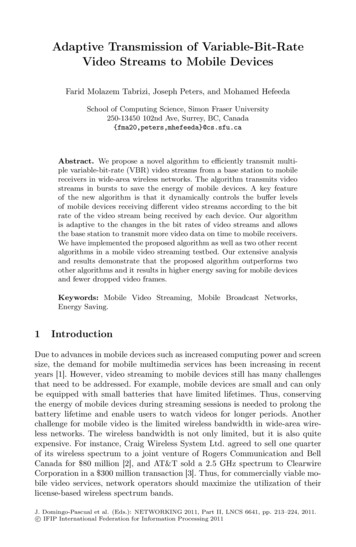
Hydraulic transmission system: Fluid coupling -: A fluid coupling isa hydrodynamic device used to transmitrotating mechanical power.It has been used inautomobile transmissions as an alternative toa mechanical clutch.
How fluid coupling can be act as amechanical clutch ?o In automotive applications, the pump typically isconnected to the flywheel of the engine The turbine isconnected to the input shaft of the transmission. Whilethe transmission is in gear, as engine speedincreases torque is transferred from the engine to theinput shaft by the motion of the fluid, propelling thevehicle . So, the behavior of the fluid coupling stronglyresembles that of a mechanical clutch driving a manualtransmission.
Construction Of a Fluid Coupling : It consists of a pump-generally known as impeller anda turbine generally known as rotor, both enclosedsuitably in a casing . They face each other with an airgap. The impeller is suitably connected to the primemover while the rotor has a shaft bolted to it. Thisshaft is further connected to the driven machinethrough a suitable arrangement. Oil is filled in thefluid coupling from the filling plug provided on itsbody.
Operating principle of fluid coupling : There is no mechanical interconnection between the impeller and the rotor andthe power is transmitted by virtue of the fluid filled in the coupling. Theimpeller when rotated by the prime mover imparts velocity and energy to thefluid, which is converted into mechanical energy in the rotor thus rotating it. Thefluid follows a closed circuit of flow from impeller to rotor through the air gap atthe outer periphery and from rotor to impeller again through the air gap at theinner periphery. To enable the fluid to flow from impeller to rotor it is essentialthat there is difference in the "heat" between the two and thus it is essentialthat there is difference in R.P.M., known as slip between the two. As the slipincreases more and more fluid can be transferred from the impeller to the rotorand more torque is transmitted.
Torque converter: Torque Converter :- Torque converter is a hydraulic transmission which increasesthe torque of the vehicle reducing its speed . It provides a continuous variation ofratio from low to high. The key characteristic of a torque converter is its ability tomultiply torque when there is a substantial difference between input and outputrotational speed, thus providing the equivalent of a reduction gear. cars withan automatic transmission have no clutch that disconnects the transmission fromthe engine. So, they use an amazing device called a torque converter.
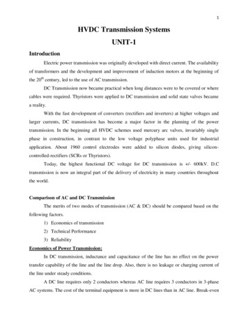
What’s Inside The Torque Converter?There are four components inside the very strong housing of the torque converter: Pump Turbine Stator Transmission fluidThese are the parts in the figure turbine,stator,pump(left to right).The housing of the torque converter is bolted to the flywheel of the engine, so it turns atwhatever speed the engine is running at. The pump inside a torque converter is a type ofcentrifugal pump. As it spins, fluid is flung to the outside. As fluid is flung to the outside, avacuum is created that draws more fluid in at the center. The fluid then enters the blades ofthe turbine, which is connected to the transmission. The turbine causes the transmission to spin,which basically moves your car. The blades of the turbine are curved. This means that the fluid,which enters the turbine from the outside, has to change direction before it exits the center ofthe turbine. It is this directional change that causes the turbine to spin.
In order to change the direction of a moving object, you must apply aforce to that object -- it doesn't matter if the object is a car or a drop offluid. And whatever applies the force that causes the object to turn mustalso feel that force, but in the opposite direction. So as the turbinecauses the fluid to change direction, the fluid causes the turbine to spin.The fluid exits the turbine at the center, moving in a different directionthan when it entered.The fluid exits the turbine moving opposite thedirection that the pump (and engine) are turning. If the fluid wereallowed to hit the pump, it would slow the engine down, wastingpower. This is why a torque converter has a stator.The stator residesin the very center of the torque converter. Its job is to redirect thefluid returning from the turbine before it hits the pump again. Thisdramatically increases the efficiency of the torque converter. Thestator has a very aggressive blade design that almost completelyreverses the direction of the fluid. A one-way clutch (inside thestator) connects the stator to a fixed shaft in the transmission (thedirection that the clutch allows the stator to spin is noted in thefigure above). Because of this arrangement, the stator cannot spinwith the fluid -- it can spin only in the opposite direction, forcing thefluid to change direction as it hits the stator blades.The figure (top to bottom) shows the pump,turbine and the stator,sending the fluid in their respective direction.
Intersting facts about stator !!! Something a little bit tricky happens when the car gets moving.There is a point, around 40 mph (64 kph), at which both the pumpand the turbine are spinning at almost the same speed (the pumpalways spins slightly faster). At this point, the fluid returns fromthe turbine, entering the pump already moving in the samedirection as the pump, so the stator is not needed. Even though the turbine changes the direction of the fluid andflings it out the back, the fluid still ends up moving in thedirection that the turbine is spinning because the turbine isspinning faster in one direction than the fluid is being pumped inthe other direction. If you were standing in the back of a pickupmoving at 60 mph, and you threw a ball out the back of thatpickup at 40 mph, the ball would still be going forward at 20 mph.This is similar to what happens in the turbine: The fluid is beingflung out the back in one direction, but not as fast as it was goingto start with in the other direction.
Manual transmission system : In this type of transmission system , the driver has to manually select andengage the gear ratios -:Stages of Manual transmission Clutch fullydepressedThe clutch is fully disengaged when the pedal is fully depressed. There will be no torquebeing transferred from the engine to the transmission and wheels. Fully depressing theclutch allows the driver to change gears or stop the vehicle. Clutch slipsThe clutch slips is the point that vary between being fully depressed and released. Theclutch slip is used to start the vehicle from a stand still. It then allows the engine rotationto adjust to the newly selected gear ratio gradually . It is recommended not to slip theclutch for a long time because a lot of heat is generated resulting in energy wastage. Clutch fully The clutch is fully engaged when the pedal is fully released. All the engine torque will berealeased transmitted to the transmission. This results in the power being transmitted to the wheelswith minimum loss.
Automatic transmission : Automatic transmission system is the most advanced system inwhich drives mechanical efforts are reduced very much anddifferent speeds are obtained automatically. This system isgenerally also called hydramatic transmission. It contain epicyclicgear arrangement, fluid coupling and torque converter. In thisplanetary gears sets are placed in series to provide transmission.This type of transmission are used by Skoda ,Toyota , Lexus , etc Epicyclic gearing (planetry gearing) :- it is a gearsystem consisting of one or more outer gears, or planet gears,revolving about a central gear .By using epicyclic gear , differenttorque speed ratio can be obtained . It also compact the size ofgear box.
Stages of automatic transmission : Park(P) :- selecting the park mode will lock the transmission, thus restricting the vehiclefrom moving. Reverse( R) :- selecting the reverse mode puts the car into reverse gear, allowing thevehicle to move backward. Neutral (N) :- selecting neutral mode disconnects the transmission from the wheel. Low (L) :- selecting the low mode will allow you to lower the speed to move on hilly andmiddy areas. Drive (D) :- selecting drive mode allows the vehicle to move and accelerate through a rangeof gears.
Comparison between manual transmissionand automatic transmission :Manual transmissionAutomatic transmissionVehicles with manual transmission areusually cheaper .Vehicles with automatic transmission arecostlier than those of manualtransmission.Manual transmission has better fueleconomy . This is because manualtransmission has better mechanical andgear train efficiency.Automatic transmission has not betterfuel economy . This is because automatictransmission has not better mechanicaland gear train efficiency as compare tothose of automatic transmission.Manual transmission offers the drivermore control of the vehicle.Automatic transmission does not offer thedriver more control of the vehicle ascompare to that of automatictransmission system.
CLUTCH A clutch is a mechanism which enables the rotary motion of one shaft to be transmitted atwill to second shaft ,whose axis is coincident with that of first. Clutch is located between engine and gear box. When the clutch is engaged, the powerflows from the engine to the rear wheels through the transmission system and the vehiclemoves . when the clutch is disengaged ,the power is not transmitted to the rear wheels andthe vehicle stops, while the engine is still running. Clutch is disengaged whena) Starting the engine,b) Shifting the gears,c) Idling the engine clutch is engaged only when the vehicle is to move and is kept engaged when the vehicle ismoving.
Function Of a Clutch :a) To permit engagement or disengagement of a gear when the vehicle is stationary and theengine is runningb) To transmit the engine power to the road wheels smoothly without shock to the transmissionsystem while setting the wheel in motion.c) To permit the engaging of gears when the vehicle is in motion without damaging the gearwheels.Principle Of Operation Of a Clutch : The clutch principle is based on friction . when two friction surface are brought in contactwith each other and pressed they are united due to friction between them. If one is revolvedthe other will also revolve . The friction between the two surfaces depends uponi. Area of the surface,ii. Pressure applied upon them,iii. Coefficient of friction of the surface materialsHere , One surface is considered as driving member and the other as driven member.
The driving member of a clutch is the flywheel mounted on the crankshaft, thedriven member is the pressure plate mounted on the transmission shaft .Friction surfaces (clutch plates ) are between the two members (driving anddriven). On the engagement of the clutch, the engine is connected to thetransmission (gear box) and the power flows from the engine to the rear wheelsthrough the transmission system . when the clutch is disengaged by pressing aclutch pedal, the engine is disconnected from the transmission and consequentlythe power does not flow to the rear wheels while the engine is still running.
Requirements Of Transmission System :- Provide means of connection and disconnection of engine with rest of power train without shock and smoothly. Provide a varied leverage between the engine and the drive wheels Provide means to transfer power in opposite direction. Enable power transmission at varied angles and varied lengths. Enable speed reduction between engine and the drive wheels in .