Transcription
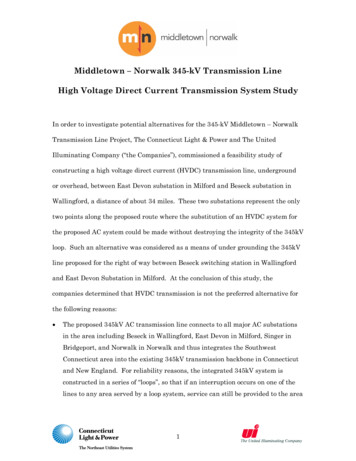
1HVDC Transmission SystemsUNIT-1IntroductionElectric power transmission was originally developed with direct current. The availabilityof transformers and the development and improvement of induction motors at the beginning ofthe 20th century, led to the use of AC transmission.DC Transmission now became practical when long distances were to be covered or wherecables were required. Thyristors were applied to DC transmission and solid state valves becamea reality.With the fast development of converters (rectifiers and inverters) at higher voltages andlarger currents, DC transmission has become a major factor in the planning of the powertransmission. In the beginning all HVDC schemes used mercury arc valves, invariably singlephase in construction, in contrast to the low voltage polyphase units used for industrialapplication. About 1960 control electrodes were added to silicon diodes, giving siliconcontrolled-rectifiers (SCRs or Thyristors).Today, the highest functional DC voltage for DC transmission is /- 600kV. D.Ctransmission is now an integral part of the delivery of electricity in many countries throughoutthe world.Comparison of AC and DC TransmissionThe merits of two modes of transmission (AC & DC) should be compared based on thefollowing factors.1) Economics of transmission2) Technical Performance3) ReliabilityEconomics of Power Transmission:In DC transmission, inductance and capacitance of the line has no effect on the powertransfer capability of the line and the line drop. Also, there is no leakage or charging current ofthe line under steady conditions.A DC line requires only 2 conductors whereas AC line requires 3 conductors in 3-phaseAC systems. The cost of the terminal equipment is more in DC lines than in AC line. Break-even
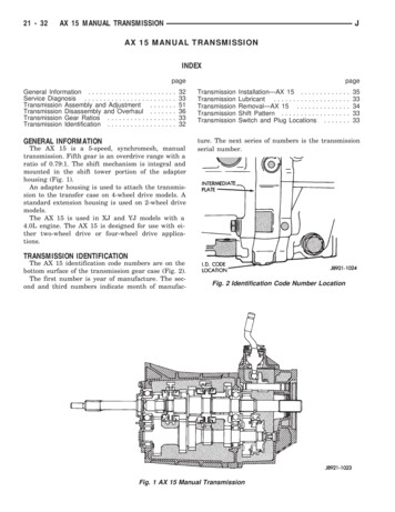
2distance is one at which the cost of the two systems is the same. It is understood from the belowfigure that a DC line is economical for long distances which are greater than the break-evendistance.Figure: Relative costs of AC and DC transmission lines vs distanceTechnical Performance:Due to its fast controllability, a DC transmission has full control over transmitted power,an ability to enhance transient and dynamic stability in associated AC networks and can limitfault currents in the DC lines. Furthermore, DC transmission overcomes some of the followingproblems associated with AC transmission.Stability Limits:The power transfer in an AC line is dependent on the angle difference between thevoltage phasors at the two line ends. For a given power transfer level, this angle increases withdistance. The maximum power transfer is limited by the considerations of steady state andtransient stability. The power carrying capability of an AC line is inversely proportional totransmission distance whereas the power carrying ability of DC lines is unaffected by thedistance of transmission.
3Voltage Control:Voltage control in ac lines is complicated by line charging and voltage drops. The voltageprofile in an AC line is relatively flat only for a fixed level of power transfer corresponding to itsSurge Impedance Loading (SIL). The voltage profile varies with the line loading. For constantvoltage at the line ends, the midpoint voltage is reduced for line loadings higher than SIL andincreased for loadings less than SIL.The maintenance of constant voltage at the two ends requires reactive power control asthe line loading is increased. The reactive power requirements increase with line length.Although DC converter stations require reactive power related to the power transmitted, the DCline itself does not require any reactive power. The steady-state charging currents in AC cablespose serious problems and make the break-even distance for cable transmission around 50kms.Line Compensation:Line compensation is necessary for long distance AC transmission to overcome theproblems of line charging and stability limitations. The increase in power transfer and voltagecontrol is possible through the use of shunt inductors, series capacitors, Static Var Compensators(SVCs) and, lately, the new generation Static Compensators (STATCOMs). In the case of DClines, such compensation is not needed.Problems of AC Interconnection:The interconnection of two power systems through ac ties requires the automaticgeneration controllers of both systems to be coordinated using tie line power and frequencysignals. Even with coordinated control of interconnected systems, the operation of AC ties can beproblematic due to:1. The presence of large power oscillations which can lead to frequent tripping,2. Increase in fault level, and3. Transmission of disturbances from one system to the other.
4The fast controllability of power flow in DC lines eliminates all of the aboveproblems. Furthermore, the asynchronous interconnection of two power systems can only beachieved with the use of DC links.Ground Impedance:In AC transmission, the existence of ground (zero sequence) current cannot be permittedin steady-state due to the high magnitude of ground impedance which will not only affectefficient power transfer, but also result in telephonic interference. The ground impedance isnegligible for DC currents and a DC link can operate using one conductor with ground return(monopolar operation).The ground return is objectionable only when buried metallic structures (such as pipes)are present and are subject to corrosion with DC current flow. While operating in the monopolarmode, the AC network feeding the DC converter station operates with balanced voltages andcurrents. Hence, single pole operation of dc transmission systems is possible for extended period,while in AC transmission, single phase operation (or any unbalanced operation) is not feasiblefor more than a second.Disadvantages of DC Transmission:The scope of application of DC transmission is limited by1. High cost of conversion equipment.2. Inability to use transformers to alter voltage levels.3. Generation of harmonics.4. Requirement of reactive power and5. Complexity of controls.Over the years, there have been significant advances in DC technology, which havetried to overcome the disadvantages listed above except for (2). These are1. Increase in the ratings of a thyristor cell that makes up a valve.2. Modular construction of thyristor valves.3. Twelve-pulse (and higher) operation of converters.4. Use of forced commutation.5. Application of digital electronics and fiber optics in the control of converters.Reliability:
5The reliability of DC transmission systems is good and comparable to that of ACsystems. The reliability of DC links has also been very good.There are two measures of overall system reliability-energy availability and transientreliability.Energy availability:Energy availability 100 (1 – equivalent outage time) %Actual timeWhere equivalent outage time is the product of the actual outage time and the fraction ofsystem capacity lost due to outage.Transient reliability:This is a factor specifying the performance of HVDC systems during recordable faults onthe associated AC systems.Transient reliability 100 X No. of times HVDC systems performed as designedNo. of recordable AC faultsRecordable AC system faults are those faults which cause one or more AC bus phasevoltages to drop below 90% of the voltage prior to the fault.Both energy availability and transient reliability of existing DC systems with thyristorvalves is 95% or more.Application of DC TransmissionDue to their costs and special nature, most applications of DC transmission generally fallinto one of the following three categories.Underground or underwater cables:In the case of long cable connections over the breakeven distance of about 40-50 km, DCcable transmission system has a marked advantage over AC cable connections. Examples of thistype of applications were the Gotland (1954) and Sardinia (1967) schemes. The recentdevelopment of Voltage Source Converters (VSC) and the use of rugged polymer DC cables,with the so-called “HVDC Light” option, are being increasingly considered. An example of thistype of application is the 180 MW Direct link connection (2000) in Australia.Long distance bulk power transmission:Bulk power transmission over long distances is an application ideally suited for DCtransmission and is more economical than ac transmission whenever the breakeven distance is
6exceeded. Examples of this type of application abound from the earlier Pacific Intertie to therecent links in China and India.The breakeven distance is being effectively decreased with the reduced costs of newcompact converter stations possible due to the recent advances in power electronics.Stabilization of power flows in integrated power system:In large interconnected systems, power flow in AC ties (particularly under disturbanceconditions) can be uncontrolled and lead to overloads and stability problems thus endangeringsystem security. Strategically placed DC lines can overcome this problem due to the fastcontrollability of DC power and provide much needed damping and timely overload capability.The planning of DC transmission in such applications requires detailed study to evaluate thebenefits. Example is the Chandrapur-Padghe link in India.Presently the number of DC lines in a power grid is very small compared to the numberof AC lines. This indicates that DC transmission is justified only for specific applications.Although advances in technology and introduction of Multi-Terminal DC (MTDC) systems areexpected to increase the scope of application of DC transmission, it is not anticipated that the ACgrid will be replaced by a DC power grid in the future. There are two major reasons for this:First, the control and protection of MTDC systems is complex and the inability of voltagetransformation in dc networks imposes economic penalties.Second, the advances in power electronics technology have resulted in the improvementof the performance of AC transmissions using FACTS devices, for instance through introductionof static VAR systems, static phase shifters, etc.Types of ValvesBased on the controllability and configuration valves are classified into four types asunder.
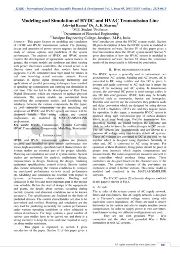
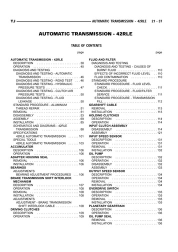
7Types of HVDC LinksThree types of HVDC Links are considered in HVDC applications which areMonopolar Link:A monopolar link as shown in the above figure has one conductor and uses either groundand/or sea return. A metallic return can also be used where concerns for harmonic interferenceand/or corrosion exist. In applications with DC cables (i.e., HVDC Light), a cable return is used.Since the corona effects in a DC line are substantially less with negative polarity of theconductor as compared to the positive polarity, a monopolar link is normally operated withnegative polarity.Bipolar Link:
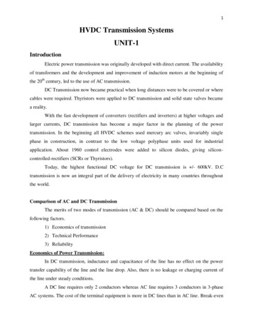
8A bipolar link as shown in the above figure has two conductors, one positive and theother negative. Each terminal has two sets of converters of equal rating, in series on the DC side.The junction between the two sets of converters is grounded at one or both ends by the use of ashort electrode line. Since both poles operate with equal currents under normal operation, there iszero ground current flowing under these conditions. Monopolar operation can also be used in thefirst stages of the development of a bipolar link. Alternatively, under faulty converter conditions,one DC line may be temporarily used as a metallic return with the use of suitable switching.Homopolar Link:In this type of link as shown in the above figure two conductors having the same polarity(usually negative) can be operated with ground or metallic return.Due to the undesirability of operating a DC link with ground return, bipolar links aremostly used. A homopolar link has the advantage of reduced insulation costs, but thedisadvantages of earth return outweigh the advantages.HVDC Converter Station
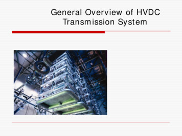
9The major components of a HVDC transmission system are converter stations whereconversions from AC to DC (Rectifier station) and from DC to AC (Inverter station) areperformed. A point to point transmission requires two converter stations. The role of rectifier andinverter stations can be reversed (resulting in power reversals) by suitable converter control.A typical converter station with two 12 pulse converter units per pole is shown in figurebelow. The block diagram of converter station is given above.Converter Unit:
10This usually consists of two three phase converter bridges connected in series to form a12 pulse converter unit as shown in above figure. The total number of valves in such a unit istwelve. The valves can be packaged as single valve, double valve or quadrivalve arrangements.Each valve is used to switch in segment of an AC voltage waveform. The converter is fed byconverter transformers connected in star/star and star/delta arrangements.The valves are cooled by air, oil, water of freon. Liquid cooling using deionized water ismore efficient and results in the reduction of station losses. The design of valves is based on themodular concept where each module contains a limited number of series connected thyristorlevels.Valve firing signals are generated in the converter control at ground potential and aretransmitted to each thyristor in the valve through a fiber optic light guide system.The valves are protected using snubber circuits, protective firing and gapless surgearrestors.Converter Transformer:The converter transformer has three different configurations(i) three phase, two winding,(ii) single phase, three winding and(iii)single phase, two windingThe valve side windings are connected in parallel with neutral grounded. The leakagereactance of the transformer is chosen to limit the short circuit currents through any valves.
11The converter transformers are designed to withstand DC voltage stresses and increasededdy current losses due to harmonic currents. One problem that can arise is due to the DCmagnetization of the core due to unsymmetrical firing of valves.Filters:There are three types of filters used which are1. AC Filters:These are passive circuits used to provide how impedance, shunt paths for ACharmonic currents. Both tuned and damped filter arrangements are used.2. DC Filters:These are similar to AC filters and are used for the filtering of DC harmonics.3. High Frequency (RF/PLC) Filters:These are connected between the converter transformer and the station AC bus tosuppress any high frequency currents. Sometimes such filters are provided on high-voltage DCbus connected between the DC filter and DC line and also on the neutral side.Reactive power source:Converter stations require reactive power supply that is dependent on the active powerloading. But part of the reactive power requirement is provided by AC filters. In addition, shuntcapacitors, synchronous condensors and static VAR systems are used depending on the speed ofcontrol desired.Smoothing Reactor:A sufficiently large series reactor is used on DC side to smooth DC current and also forprotection. The reactor is designed as a linear reactor and is connected on the line side, neutralside or at intermediate location.DC Switchgear:It is modified AC equipment used to interrupt small DC currents. DC breakers orMetallic Return Transfer Breakers (MRTB) are used, if required for interruption of rated loadcurrents.In addition to the DC switchgear, AC switchgear and associated equipment for protectionand measurement are also part of the converter station.Modern Trends in DC TransmissionTo overcome the losses and faults in AC transmission, HVDC transmission is preferred.
12The trends which are being introduced are for the effective development to reduce thecost of the converters and to improve the performance of the transmission system.Power semiconductors and valves:The IGBTs or GTOs employed required huge amount of current to turn it ON which wasa big problem. GTOs are available at 2500V and 2100A. As the disadvantage of GTOs is thelarge gate current needed to turn them OFF, so MCT which can be switched OFF by a smallcurrent is preferred as valves.The power rating of thyristors is also increased by better cooling methods. Deionizedwater cooling has now become a standard and results in reduced losses in cooling.Converter Control:The development of micro-computer based converter control equipment has madepossible to design systems with completely redundant converter control with automatic transferbetween systems in the case of a problem.The micro-computer based control also has the flexibility to implement adaptive controlalgorithms or even the use of expert systems for fault diagnosis and protection.DC Breakers:Parallel rather than series operation of converters is likely as it allows certain flexibilityin the planned growth of a system. The DC breaker ratings are not likely to exceed the full loadratings as the control intervention is expected to limit the fault current.Conversion of existing AC lines:There are some operational problems due to electromagnetic induction from AC circuitswhere an experimental project of converting a single circuit of a double circuit is under process.Operation with weak AC systems:The strength of AC systems connected to the terminals of a DC link is measured in termsof Short Circuit Ratio (SCR) which is defined asSCR Short circuit level at the converter busRated DC PowerIf SCR is less than 3, the AC system is said to be weak. The conventional constantextinction angle control may not be suitable for weak AC systems.
13Constant reactive current control or AC voltage control may overcome some of theproblems of weak AC systems.The power modulation techniques used to improve dynamic stability of power systemswill have to be modified in the presence of weak AC systems.Six Pulse ConvertersThe conversion from AC to DC and vice-versa is done in HVDC converter stations byusing three phase bridge converters. The configuration of the bridge (also called Graetz circuit)is a six pulse converter and the 12 pulse converter is composed of two bridges in series suppliedfrom two different (three-phase) transformers with voltages differing in phase by 30 o .Pulse NumberThe pulse number of a converter is defined as the number of pulsations (cycles of ripple)of direct voltage per cycle of alternating voltage.The conversion from AC to DC involves switching sequentially different sinusoidalvoltages onto the DC circuit.
14A valve can be treated as a controllable switch which can be turned ON at any instant,provided the voltage across it is positive.The output voltage Vd of the converter consists of a DC component and a ripple whosefrequency is determined by the pulse numberChoice of Converter ConfigurationThe configuration for a given pulse number is so chosen in such a way that the valve andtransformer are used to the maximum.A converter configuration can be defined by the basic commutation group and thenumber of such groups connected in series and parallel.If there are ‘q’ valves in a basic commutation group and r of those are connected inparallel and s of them in series then,p qrsNote:
15A commutation group is defined as the group of valves in which only one (neglectingoverlap) conducts at a time.Valve Rating:The valve rating is specified in terms of Peak Inverse Voltage (PIV). The ratio of PIV toaverage DC voltage is an index of valve utilization.So, average maximum DC voltage across the converter is given by, qVdo s2 sq E cos td ( t )mq sqqsq E m (sin t ) / q/ q E m sin sin E m .2 sin2 2 q q 2 qVdo sq E m sin q----- (1)If ‘q’ is even, then maximum inverse voltage occurs when the valve with a phasedisplacement of 180o is conducting and is given by,PIV 2EmIf ‘q’ is odd, then maximum inverse voltage occurs when the valve with a phase shift ofπ (π/q) is conducting and is given by,PIV 2Em cos(π/2q)The valve utilization factor is given byFor q even,2EmPIV2 sq VdoE m sins.q. sin qq2 E m cosFor q odd,PIV sqVdo 2qE m sin q2 . cos sq. sin(Since sin2θ 2sinθcosθ and 2 cos 2q 2q qsin 2q2 . cos sq.2 cos sin 2q 2qsin 2q2 sin )2qq
16PIV Vdo sq. sin (For q odd)2qTransformer Rating:The current rating of a valve is given by,Iv Id------ (2)r qwhere, Id is the DC current which is assumed to be constant.The transformer rating on the valve side (in VA) is given by,S tv pEm2Iv
17From equations (1), (2) & p qrs, we haveVdo . S tv p2 .sq. sinS tv STransformer utilization factor tv Vdo I d 2.Id. r qqVdo I dq . sin q is a function of q. As AC supply is three phase so, commutation group of three valves can be easilyarranged. So, for q 3,S tv Vdo I d (2 X 3) sin 3S tv Vdo I d6 sin 60 oS tv 1.48Vdo I dTransformer utilization can be improved if two valve groups can share single transformerwinding. In this case, the current rating of the winding can be increased by a factor of 2 whiledecreasing the number of windings by a factor of 2.
18It is a 6-pulse converter consisting of two winding transformer where the transformerutilization factor is increased when compared to three winding transformer.The series conduction of converter groups has been preferred because of controlling andprotection as well as the requirements for high voltage ratings. So, a 12 pulse converter isobtained by series connection of two bridges.The 30o phase displacement between two sets of source voltages is achieved bytransformer connections Y-Y for one bridge and Y- for the other bridge.The use of a 12 pulse converter is preferable over the 6 pulse converter because of thereduced filtering requirements.Analysis of Graetz Circuit without overlap:At any instant, two valves are conducting in the bridge, one from the upper commutationgroup and the second from the lower commutation group. The firing of the next valve in aparticular group results in the turning OFF of the valve that is already conducting. The valves arenumbered in the sequence in which they are fired. Each valve conducts for 120 o and the intervalbetween consecutive firing pulse is 60 o in steady state.The following assumptions are made to simplify the analysisa. The DC current is constant.b. The valves are modeled as ideal switches with zero impedance when ON and withinfinite impedance when OFF.c. The AC voltages at the converter bus are sinusoidal and remain constant.One period of the AC supply voltage can be divided into 6 intervals – each correspondingto the conduction of a pair of valves. The DC voltage waveform repeats for each interval.Assuming the firing of valve 3 is delayed by an angle α , the instantaneous DC voltageVd during the interval is given byVd eb – ec ebcfor α ωt α 60oLet eba 2 E LL sin tthen ebc 2E LL sin( t 60 o )Average DC Voltage Vd 3 3 60o 2 E LL sin( t 60 o )d t2 E LL [cos( 60 o cos( 120 o )]
19Vd 3 2 E LL cos 1.35E LL cos Vd Vdo cos ------- (1)The above equation indicates that for different values of α , V d is variable.The range of α is 180 o and correspondingly Vd can vary from Vdo to –Vdo . Thus, thesame converter can act as a rectifier or inverter depending upon whether the DC voltage ispositive or negative.DC Voltage Waveform:The DC voltage waveform contains a ripple whose fundamental frequency is six timesthe supply frequency. This can analyzed in Fourier series and contains harmonics of the orderh npwhere, p is the pulse number and n is an integer.The rms value of the hth order harmonic in DC voltage is given byVh Vdo2[1 (h 2 1) sin 2 ]1 / 2h 12The waveforms of the direct voltage and calve voltage are shown for different values ofα.
20AC Current Waveform:It is assumed that direct current has no ripple (or harmonics). The AC currents flowingthrough the valve (secondary) and primary windings of the converter transformer containharmonics.The waveform of the current in a valve winding is shown. The rms value of thefundamental component of current is given byI1 1 22 /3 I dcos .d /36 I d ---- (2)where as the rms value of the current isI 2.I d3The harmonics contained in the current waveform are of the order given byh np 1Where n is an integer, p is the pulse number. For a six pulse converter, the order of ACharmonics is 5, 7, 11, 13 and higher order. These are filtered out by using tuned filters for eachone of the first four harmonics and a high pass filter for the remaining.The rms value of hth harmonic is given byIh I1hPower Factor:The AC power supplied to the converter is given byPAC 3E LL I1 cos Where cos is the power factor.The DC power must match the AC power ignoring the losses in the converter. Thus,PAC PDC Vdo I d 3E LL I1 cos Substituting for Vdo and I1 from equations (1) and (2) in the above equation, we getcos cos
21The reactive power requirements are increased as α is increased from zero (or reducedfrom 180o ).Analysis of Graetz Circuit with overlapDue to the leakage inductance of the converter transformers and the impedance in thesupply network, the current in a valve cannot change suddenly and this commutation from onevalve to the next cannot be instantaneous. This is called overlap and its duration is measured bythe overlap (commutation) angle ‘μ’.Each interval of the period of supply can be divided into two subintervals as shown in thebelow timing diagram. In the first subinterval, three valves are conducting and in the secondsubinterval, two valves are conducting which is based on the assumption that the overlap angle isless than 60o .There are three modes of the converter which arei) Mode 1 – Two and three valve conduction (μ 60o )ii) Mode 2 – Three valve conduction (μ 60o )iii) Mode 3 – Three and four valve conduction (μ 60o )i)Analysis of Two and Three Valve Conduction Mode:The equivalent circuit for three valve conduction is shown below.For this circuit,di dieb ea Lc 3 1 dt dt The LHS in the above equation is called the commutating emf whose value is given byeb ea 2 E LL sin tWhich is the voltage across valve 3 just before it starts conducting.
22Since, i1 I d i3We get,2 E LL sin t 2 Lcdi3dtSolving the above equation, we geti3 (t ) I s (cos cos t ), t Where,2 E LL2 LcIs At ωt α μ , is Id . This givesI d I s [cos cos( )]The average direct voltage can be obtained as3 Vd 60 3ec d ( t ) (eb ec )d ( t ) 2 Vdo cos Since,Vd 3 2 32 2 E LL [cos cos( )]E LL Vdo , we getVdo[cos cos( )]2The value of [cos cos( )] can be substituted to get, IVd Vdo cos d2I s Vdo cos Rc I d Where,Rc 3 Lc 3 XcRc is called equivalent commutation resistance and the equivalent circuit for a bridgeconverter is shown below.
23Inverter Equations:For an inverter, advance angle β is given byβ π-αand use opposite polarity for the DC voltage with voltage rise opposite to the direction ofcurrent. Thus,Vdi Vdoi[cos cos( )]2 Vdoi[cos( ) cos( )]2Vdi Vdoi[cos cos ]2Where, the extinction angle γ is defined asγ β-μ π-α-μSimilarly, it can be shown thatVdi Vdoi cos Rci I d Vdoi cos Rci I dThe subscript “i” refers to the inverter.ii) Analysis of Three and Four Valve Conduction Mode:The equivalent circuit for three and four valve conduction is shown below.For, α ωt α μ-60oi1 Is sin(ωt 60o ) Ai6 Id – i2 Id – Is sinωt CWhere, I s Em2 Is Lc3The constant A can be determined from the initial conditioni1 (ωt α) Id Is sin(α 60o ) AThe constant C can be determined from the final conditioni6 (ωt α μ-60o ) 0 Id – Is sin(α μ-60o ) C 0
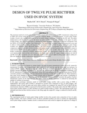
24For, α μ-60o ωt α 600i1 Is cosωt BThe constant B can be determined from the continuity equationi1 (ωt α μ 60o ) Is sin(α μ) A Is cos(α μ-60o ) BFinally,Id Is[cos( 30 o ) cos( 30 o )]2The expression for average direct voltage is given byVd 3 60o 60o 3ec d ( t )2Since ec Em cosωtVd 33Em [sin( 60 o ) sin( 60 o )] 2Vd 3Vdo [cos( 30 o ) cos( 30 o )]2FinallyVd Vdo [ 3 cos( 30 o ) 3 Id] 3.Vdo cos( 30 o ) 3Rc I d2 IsConverter Bridge CharacteristicsA) Rectifier: The rectifier has three modes of operation.1) First mode: Two and three valve conduction mode ( μ 60 o )2) Second mode: Three valve conduction mode only for α 30 o ( μ 60o )3) Third mode: Three and four valve conduction mode α 30 o ( 60o μ 120o )As the DC current continues to increase, the converter operation changes over frommode 1 to 2 and finally to mode 3.The DC voltage continues to decrease until it reaches zero.
25For α 30o , mode 2 is bypassed.For Modes 1 and 3, we haveVdI cos dVdo2I sVd3I 3 cos( 30 o ) dVdo2I sThe voltage and current characteristics are linear with different slopes in these cases.For mode 2, μ 60o , μ is constant, so the characteristics are elliptical and is given by V d cos 2 2 I d sin 2 where, Vd 2 1 VdIand I d dVdo2I sB) Inverter:The inverter characteristics are similar to the rectifier characteristics. However, theoperation as an inverter requires a minimum commutation margin angle during which the voltageacross the valve is negative. Hence the operating region of an inverter is different from that for arectifier.So, the margin angle (ξ) has different relationship to γ depending on the range ofoperation which areFirst Range:β 60o and ξ γSecond Range:60o β 90o and ξ 60o – μ γ-(β-60o )Third Range:β 90o and ξ γ – 30oIn the inverter operation, it is necessary to maintain a certain minimum margin angle ξ owhich results in 3 sub-modes of the 1st mode which areMode 11(a)β 60o for values of μ (60o - ξo )The characteristics are linear defined byVd cosγo – Id 1(b) 60o β 90o forμ 60o – ξo 60o – γo constant
26The characteristics are elliptical.o1(c) 90 β 90o ξo for values of μ in the range60o – ξo μ 60oThe characteristics in this case are line and defined byVd cos( γo 30o ) - Id Mo
Electric power transmission was originally developed with direct current. The availability of transformers and the development and improvement of induction motors at the beginning of the 20th century, led to the use of AC transmission. DC Transmission now became practical when long distances were to be covered or where cables were required.