Transcription
1Modeling and Control for Smart Grid Integrationof Solar/Wind Energy Conversion SystemE. M. Natsheh, Member, IEEE, A. Albarbar, Member, IEE, and J. Yazdani, Member, IEEEAbstract-- Performance optimization, system reliability andoperational efficiency are key characteristics of smart gridsystems. In this paper a novel model of smart grid-connectedPV/WT hybrid system is developed. It comprises photovoltaicarray, wind turbine, asynchronous (induction) generator,controller and converters. The model is implemented usingMATLAB/SIMULINK software package. Perturb and observe(P&O) algorithm is used for maximizing the generated powerbased on maximum power point tracker (MPPT)implementation. The dynamic behavior of the proposed model isexamined under different operating conditions. Solar irradiance,temperature and wind speed data is gathered from a gridconnected, 28.8kW solar power system located in centralManchester. Real-time measured parameters are used as inputsfor the developed system. The proposed model and its controlstrategy offer a proper tool for smart grid performanceoptimization.Index Terms-- Control systems, Hybrid power systems,MATLAB, Modeling, Photovoltaic systems, Power electronics,Smart grids, Wind power generation.I. INTRODUCTIONTHE limitations of global resources of fossil and nuclearfuel, has necessitated an urgent search for alternativesources of energy. Therefore, a new way has to be foundto balance the supply and demand without resorting to coaland gas fuelled generators. Smart grid is a system that wouldenable the integration of renewable energy sources and shiftfrom reliance on fossil fuels, while maintaining the balancebetween supply and demand. The key characteristics of smartgrid include [1]: Grid optimisation: system reliability and operationalefficiency. Distributed generation: not only traditional large powerstations, but also individual PV panels, micro-wind,etc. Advanced metering infrastructure (AMI): smart meters. Grid-scale storage. Demand response.This work was supported in part by Manchester Metropolitan UniversitySchool of Engineering and An-Najah National University Department ofComputer Engineering.E. M. Natsheh is with the School of Engineering, ManchesterMetropolitan University, Manchester, UK (e-mail: emad.nat@gmail.com ).A. Albarbar is with the School of Engineering, Manchester MetropolitanUniversity, Manchester, UK (e-mail: a.albarbar@mmu.ac.uk ).J. Yazdani is with the University of Central Lancashire, Preston, Lancashire,UK (e-mail: jyazdani@uclan.ac.uk ). Plug-in hybrid electric vehicles (PHEVs) and vehicle togrid (V2G).This paper focuses mainly on the smart grid integration ofPV/WT hybrid system (grid optimisation and distributiongeneration).Over recent years several research and investment has beencarried out in hybrid power system, such as Yang [2], whorecommended an optimal design model for hybrid solar–windsystem, which employs battery banks to calculate the system’soptimum configurations in China. Dihrab [3], presented ahybrid solar-wind system as a renewable source of powergeneration for grid connected application in three cities inIraq. Reichling [4], modeled a hybrid solar wind power plantin south western Minnesota for a two year period, using hourlysolar irradiation and wind speed data. Ekren [5], showed anoptimum sizing procedure of PV/wind hybrid system inTurkey. Several modeling studies on PV/WT power systemhave been conducted. Among them, Kim [6], developed agrid-connected photovoltaic model using PSCAD/EMTDC forelectromagnetic transient analysis. Tsai [7], implemented aninsulation-oriented PV model using MATLAB/SIMULINKsoftware package. Gow [8], developed a general PV modelwhich can be implemented on simulation platforms such asPSPICE or SABER. Khan [9], presented the model of a smallwind-fuel cell hybrid energy system and analyzed life cycle ofa wind-fuel cell integrated system. Chayawatto [10],developed a mathematical model of a dc/ac full-bridgeswitching converter with current control for PV gridconnected system under islanding phenomena; thisphenomena occur when the grid system is disconnected forany reason and the distributed generation still supplies to anysection of local loads. Onar [11], modeled a hybrid wind/FC/ultra-capacitor (UC) power system for a grid-independent userwith appropriate power flow controllers.In this study, a detailed dynamic model, control andsimulation of a smart grid-connected PV/WT hybrid powergeneration system is proposed. Modeling and simulation ms software packages to verify theeffectiveness of the proposed system.II. SYSTEM DESCRIPTION AND MODELINGSmart grid is a system consists of three layers: the physicalpower layer, the control layer and the application layer. Andaccording to, Katherine Hamilton [1], smart grid has to bedynamic and have constant two-way communication, as
2shown in Fig.1. So, for example, with PV panels on the roofs,intelligent building system will generates, store and use theirown energy. Hence, as active buildings they become part ofthe smart grid. This could save energy and increase reliabilityand transparency.Fig. 3. Single diode PV cell equivalent circuitelectric charge 1.6 x 10⁻¹⁹ Coulombs, K is Boltzmann’sconstant 1.38 x 10⁻²³ J/K, F is the cell idealizing factor, Tc isthe cell’s absolute temperature, vd is the diode voltage, and Rpis the parallel resistance. The photocurrent (Igc) mainlydepends on the solar irradiation and cell temperature, which isdescribed as [13]I gc [μ sc (Tc Tr ) I sc ] GFig. 1. General layout of the smart gridIn this section, the dynamic simulation model is describedfor photovoltaic/wind turbine hybrid generation system. Thedeveloped system consists of a photovoltaic array, dc/dcconverter with an isolated transformer, designed for achievingthe MPP with a current reference control (Iref) produced byP&O algorithm, wind turbine, asynchronous inductiongenerator, and ac/dc thyristor controlled double-bridgerectifier. The block diagram of the developed system is shownin Fig. 2.A. Modeling and Design of a Photovoltaic ModuleThe general mathematical model for the solar cell has beenstudied over the past three decades [12]. The circuit of thesolar cell model, which consists of a photocurrent, diode,parallel resistor (leakage current) and a series resistor; isshown in Fig. 3. According to both the PV cell circuit shownin Fig. 3 and Kirchhoff’s circuit laws, the photovoltaic currentcan be presented as follows [13]:I pv I gc evd v KFT I o exp c 1 d Rp (1)Where Igc is the light generated current, Io is the darksaturation current dependant on the cell temperature, e is the(2)Where μsc is the temperature coefficient of the cell’s shortcircuit current, Tref is the cell’s reference temperature, Isc is thecell’s short circuit current at a 25oC and 1kW/m2, and G is thesolar irradiation in kW/m2. Furthermore, the cell’s saturationcurrent (Io) varies with the cell temperature, which isdescribed as [13]3 ev g 11 T KF T T I o I oα c exp r c Tr I scI oα ev exp(3)(4) oc KFT c Where Ioα is the cell’s reverse saturation current at a solarradiation and reference temperature, Vg is the band-gap energyof the semiconductor used in the cell, and Voc is the cells opencircuit voltage. In this study, a general PV model is built andimplemented using MATLAB/SIMULINK to verify thenonlinear output characteristics for the PV module. Theproposed model is implemented, as shown in Fig. 4. In thismodel, whereas the inputs are the solar irradiation and celltemperature, the outputs are the photovoltaic voltage andcurrent. The PV models parameters are usually extracted fromthe manufactures data sheet.Fig. 2. Block diagram of the proposed system
3Fig. 5. Subsystem implementation of the WT modelFig. 4. Subsystem implementation of the PV modelB. Modeling and Design of a WT and Induction GeneratorSeveral studies have been reported regarding to WT andwind generators [14]. In this study, the proposed WT model isbased on the wind speed versus WT output powercharacteristics. The output power of the wind turbine is givenby [15]:Pm c p (λ , β )ρA23vwind(5)Where Pm is the mechanical output power of the turbine, cpis the performance coefficient of the turbine, λ is the tip speedratio of the rotor blade, β is the blade pitch angle, ρ is the airdensity, A is the turbine swept area, and υwind is the windspeed.The performance coefficient model cp (λ,β) used in thispaper is taken from [16] and given by: c2 c5 λi c p (λ , β ) c1 c 3 β c4 e c6 λ λi (6)Where constants c1 to c6 are parameters that depend on thewind turbine rotor and blade design, and λi is a parametergiven in (7).1λi 10.035 3λ 0.08β β 1(7)Furthermore, (5) can be normalized and simplified forspecific values of A and ρ, as in (8):3Pm pu k p c p pu vwind puThe wind turbine induction generator (WTIG) model isdesigned using the built-in SimPowerSystem library. The rotorshaft is driven by the WT which produces the mechanicaltorque according to the generator and wind speed values. Theelectrical power output of the generator (stator winding) isconnected to the smart grid.C. Power Control Systems1) Photovoltaic Control SystemThe output characteristics of the PV model with differentsolar irradiance and cell temperature are nonlinear.Furthermore, the solar irradiation is unpredictable, whichmakes the maximum power point (MPP) of the PV modulechanges continuously. Therefore, a maximum power pointtracker (MPPT) technique is needed to operate the PV moduleat its maximum power point (MPP). Perturb and observe(P&O) algorithm is the maximum power point tracker (MPPT)control algorithm that will be adapted in this model. The P&Oalgorithm operates by periodically incrementing ordecrementing the PV array operating current, and comparingthe PV output power with the previous one. If it’s positive thecontrol system moves the PV array operating point in the samedirection, otherwise, it’s moved in the opposite direction.A MPPT controller model is built and implemented usingMATLAB, to operate the PV module at its maximum powerpoint. The P&O algorithm requires two measurements:measurement of the current (Ipv) and measurement of thevoltage (Vpv). The proposed model is implemented as shown inFig. 6.(8)Where Pm-pu is the power in per unit (p.u.) of nominalpower for particular values of ρ and A, cp-pu is the p.u. value ofthe performance coefficient cp, kp is the power gain, υwind-pu isthe p.u. value of the base wind speed. The based wind speed isthe mean value of the expected wind speed in (m/s).The modified model of the WT is implemented as shown inFig. 5. In this model, whereas the inputs are the wind speedand generator speed, the output is the torque applied to thegenerator shaft. The torque of the generator is based on thegenerator power and speed.Fig. 6. Subsystem implementation of the MPPT controller modelIn addition, a dc averaged switched model converter withinput current control (Iref) is built and implemented usingMATLAB/SIMULINK, to reduce the switching harmonicsand steps-up the photovoltaic voltage to a higher dc voltage(e.g. 400V). The proposed model is implemented as shown inFig.7.
4firing angle (α) is controlled by a discrete PI controller. Theproposed WT control system model is implemented as shownin Fig. 10.Fig. 7. Subsystem implementation of the dc/dc converter modelHowever, when the PV system with a MPPT is connectedto the power electronic converters (PEC), an automaticfeedback controller will be needed to balance the power andmaintain the direct voltage constant; especially when thesystem is running under various conditions. The proposed PVcontrol system model is implemented as shown in Fig. 8(a)and 8(b).Fig. 10. The double-bridge rectifier, filters elements and control system model3) dc/ac inverter for load sideAn ac averaged switched model inverter is built andimplemented using MATLAB/SIMULINK, to convert thedirect current (dc) into alternating current (ac), at a switchingfrequency (fs) greater than the AC line frequency (50Hz 60Hz). Losses are included due to output-port series resistance(ROP) and input-port switching loss current (IIP).The proposedmodel is implemented as shown in Fig. 11.Fig. 8(a) Implementation of the PV control system modelFig. 8(b) Subsystem implementation of the feedback controller model2) Wind Turbine Control SystemDue to the variations in wind speed, the output power ofthe wind turbine induction generator experiences variations infrequency and amplitude. Therefore, a controllable ac/dcconverter is used to smooth the wind turbine output powerbefore being supplied to other electronic devices. Fig. 9,shows the schematic of the double-bridge rectifier.Fig. 9. The double-bridge rectifierOne of the advantages of the double-bridge rectifier is thecontrollable dc output voltage, by tuning the firing angle (α) ofthe 12-pulse synchronized PWM generator, and the narrowedcommutation periods, which causes less harmonic distortioneffects on the source side. In this model a three-phase twowinding transformer is used to obtain six input ports withappropriate phase angles for the double-bridge rectifier. TheFig. 11. Subsystem implementation of the dc/ac inverter modelIII. SIMULATION RESULTS AND DISCUSSIONThe block diagram of the integrated photovoltaic/windturbine system, and the power controllers are shown in Fig. 2.The major inputs for the proposed PV model were solarirradiation, PV panel temperature and PV manufacturing datasheet information’s. In this study, Astronergy CHSM6610PPV panel is taken as example. The Astronergy CHSM6610Pkey specification is listed in Table I.Table IAstronergy CHSM6610P specifications (1kW/m2, 25o C)ParameterValueMaximum power (Pm)225 (W)Open circuit voltage (Voc)36.88 (V)Voltage at Pm (Vamp)29.76 (V)Short circuit current (Isc)8.27 (A)7.55 (A)Current at Pm (Iamp)Temp coefficient for Pm-0.46 (% / oC)Temp coefficient for Voc-0.129 (V / oC) 0.052 (% / C)Temp coefficient for IscNo. of cells and connections60 in seriesThe I-V and P-V output characteristics for the PV modelare shown in Fig.12. The output power and current of PVmodule depend on the solar irradiance and temperature, andcell’s terminal operating voltage as well. It was found fromFig. 12(a) and 12(b) that with increased solar irradiance there
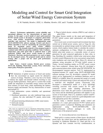
5is an increase in both the maximum power output and the shortcircuit current. On the other hand, we observe from Fig. 12(c)and 12(d) that with an increase in the cell temperature, themaximum power output decreases whilst the short circuitcurrent increases.(a)the power in the wind is a cubic function of wind speed,changes in speed produce a profound effect on power.(b)Fig. 13. Wind turbine characteristicsThe parameters of the boost type dc/dc converter located atthe output of the PV system are given in Table III.The parameters of the double-bridge rectifier are given inTable IV.Table IIIdc/dc converter model parameters(d)(c)Fig. 12. I-V and P-V output characteristics (a - b) with different G (c - d) withdifferent TcThe parameters of the wind turbine induction generator aregiven in Table II.Table IIWind Turbine Induction generator parametersValueParameterTurbine dataBase wind speed (wbase)Maximum power at wbase (kp)Coefficient (c1-c6)Nominal performance coefficientGenerator dataRotor typeNominal power (Pmechanic)Nominal voltage (line-to-line)Nominal frequencyNominal revolutions per minuteStator resistanceStator inductanceRotor resistanceRotor inductanceMagnetizing inductanceInertia constantFriction factorPairs of poles9 (m/s)1 (p.u.)[0.5176, 116, 0.4, 5, 21,0.0068]0.48 (p.u.) for [β 0o, λ 8.1 ]Squirrel cage200 (HP)460 (V)60 (Hz)1785 (rpm)0.01282 (p.u.)0.05051 (p.u.)0.00702 (p.u.)0.05051 (p.u.)6.77 (p.u)0.3096 (s)0.0114 (p.u.)2The generator speed (rpm) and the generator power (p.u.)characteristics for the WT model are shown in Fig. 13corresponding to various wind speed values. The output powerof WT depends on the wind speed and generator speed. Asdepicted in Fig.13, wind speed is the most influential factor onthe amount of power produced by the wind turbine. BecauseParameterInput port series resistanceSwitching loss currentCapacitanceInitial capacitor voltageValue0.50.03200 (µF)400 (V)Table IVDouble-bridge rectifier model parametersParameterValuePulse width of synchronized 12-pulse generator80 (o)Proportional gain of PI voltage control system2Integral gain of PI voltage control system20Snubber resistance of one thyristor2 (kΩ)Snubber capacitance of one thyristor0.1 (µF)Internal resistance of one thyristor1 (mΩ)Filter inductance66 (mH)Filter capacitance3300 (µF)Reference voltage400 (V)Finally, Table V shows the parameters of the inputtransformer used in the double-bridge rectifier.Table VTransformer parametersParameterValueNominal power120 (kW)Nominal frequency60 (Hz)Input winding parameters[460 (V) 0.00025 (p.u.) 0 (p.u.)](Yg) [V1 R1 L1]Output winding parameters[230 (V) 0.00025 (p.u.) 0.0024 (p.u.)](Y) [V2 R2 L2]Output winding parameters[230 (V) 0.00025 (p.u.) 0.0024 (p.u.)](Delta) [V3 R3 L3]Magnetization resistance368.62 (p.u.)Magnetization inductance368.62 (p.u.)
6Fig. 14(a) Solar radiation and panel temp profiles used for system simulationFig. 14(b) Wind speed profile used for system simulationDuring the simulation process, the aim was to observe theproposed model behavior over a long time period, includingday and night cases. The solar radiation and wind speedprofiles are used to test the performance of the proposedhybrid system model, as shown in Fig. 14(a) and 14(b). Theirradiance, temperature and wind speed data was gatheredfrom a 28.8kW grid connected solar power system located incentral Manchester. These real-time parameters are used asinputs of the developed PV-wind turbine hybrid model.Although the photovoltaic voltage fluctuates due to solarradiation variations, the proposed control system of the solarpower plant successfully keeps the load voltage stable at400V. The output voltage of the dc/dc converter is depicted inFig.15. The output voltage of the PV panel is depicted inFig.16.The objective of the P&O algorithm is to adjust the dc/dccontrol variable (Iref), so that the PV array operates at themaximum power point (MPP). And that done, by periodicallyincrementing or decrementing the PV array operating current(Ipv Iref), as shown in Fig. 17.From Fig. 18, we observe that in the early morning before8:30am and in the evening after 19:00pm, the solar power isunavailable due to nonexistence of solar radiation. Toovercome this deficiency of the PV system, and to increase theamount of power in the early morning, the wind turbinesystem was added to the solar power plant.In this study, the stator winding is connected to the grid andthe rotor is driven by the wind turbine. The power captured bythe wind turbine is converted into electrical power by theinduction generator and is transmitted to the grid by the statorwinding. As shown in Fig. 14(b), 24-h duration is used for thesimulations with a variation in wind speed. This variation inwind speed affects the power produced by the inductiongenerator coupled to the wind turbine as observed in Fig. 19.From Fig. 20, we observe that although the available powerfrom the wind generator fluctuates due to wind speedvariations, the PI controlled firing angle (α) of the doublebridge ac/dc converter successfully maintains the outputvoltage of the WTIG at 400V.Since the voltage of the two dc buses is kept at 400V, dc/acinverters are used to deliver the required power to the loadside at 60Hz frequency and 240V line-to-line voltage.The power delivered to the load side by the PV/WT hybridtopology is illustrated in Fig. 21.Fig. 15. Output voltage of the dc/dc converterFig. 16. Output voltage of the PV panel
7Fig. 17. Output current of the MPPT (Iref Ipv)Fig. 18. Total power of the solar power plant (160 Astronergy CHSM6610PPV panel)Fig. 20. Output voltage of the double-bridge ac/dc converterFig. 21. Power delivered to load side by the hybrid topologyIV. CONCLUSIONSFig. 19. Power of the generator coupled to the wind turbineIn this paper, a novel PV/WT hybrid power system isdesigned and modelled for smart grid applications. Thedeveloped algorithm comprises system components and anappropriate power flow controller. The model has beenimplemented using the MATLAB/SIMULINK softwarepackage, and designed with a dialog box like those used in theSIMULINK block libraries. The available power from the PVsystem is highly dependent on solar radiation. To overcomethis deficiency of the PV system, the PV module wasintegrated with the wind turbine system. The dynamicbehavior of the proposed model is examined under differentoperating conditions. Solar irradiance, temperature and windspeed data is gathered from a 28.8kW grid connected solarpower system located in central Manchester. The developedsystem and its control strategy exhibit excellent performancefor the simulation of a complete day. The proposed modeloffers a proper tool for smart grid performance optimization.
8V. REFERENCES[1] E. Miller, “Smart grids – a smart idea?,” Renewable Energy FocusMagazine, vol. 10, pp. 62-67, Sep.-Oct. 2009.[2] H. Yang, Z. Wei, and L. Chengzh, “Optimal design and techno-economic analysis of a hybrid solar-wind power generationsystem,” Applied Energy, vol. 86, pp. 163-169, Feb. 2009.[3] S. Dihrab, and K. Sopian, “Electricity generation of hybrid PV/windsystems in Iraq,” Renewable Energy, vol. 35, pp. 1303-1307, Jun.2010.[4] J.P. Reichling, and F.A. Kulacki, “Utility scale hybrid wind-solarthermal electrical generation: a case study for Minnesota,” Energy,vol. 33, pp.626-638, Apr. 2008.[5] O. Ekren, B.Y. Ekren, and B. Ozerdem, “Break-even analysis andsize optimization of a PV/wind hybrid energy conversion systemwith battery storage – A case study” Applied Energy, vol.86, pp.1043-1054, July-August 2009.[6] S.K. Kim, J.H. Jeon, C.H. Cho, E.S. Kim, and J.B. Ahn, “Modelingand simulation of a grid-connected PV generation system forelectromagnetic transient analysis, ”Solar Energy, vol.83, pp. 664678, May 2009.[7] H.L Tsai, “Insolation-oriented model of photovoltaic module usingMatlab/Simulink,” Solar Energy, vol. 84, pp. 1318-1326, July2010.[8] J.A. Gow, and C.D. Manning, “Development of a photovoltaic arraymodel for use in power-electronics simulation studies,” IEEProceedings- Electric Power Applications, vol. 146, pp. 193-199,Mar. 1999.[9] M.J. Khan, and M.T. Iqbal, “Dynamic modeling and simulation of asmall wind fuel cell hybrid energy system,” Renewable Energy,vol. 30, pp. 421-439, Mar. 2005.[10] N. Chayawatto, K. Kirtikara, V. Monyakul, C. Jivacate, and D.Chenvidhya, “DC–AC switching converter modelings of a PVgrid-connected system under islanding phenomena,” RenewableEnergy, vol. 34, pp. 2536-2544, Dec. 2009.[11] O.C. Onara, M. Uzunoglua, and M.S. Alam, “Dynamic modeling,design and simulation of a wind/fuel cell/ultra-capacitor-basedhybrid power generation system, “Journal of Power Sources, vol.161, pp. 707-722, Oct. 2006.[12] J.C.H. Phang, D.S.H. Chan, and J.R. Philips, “Accurate analyticalmethod for the extraction of solar cell model parameter,” IEEEElectronics Letters, vol. 20, pp.406-408, May 1984.[13] M.G. Villalva, J.R. Gazoli, and E.R. Filho, “Comprehensiveapproach to modeling and simulation of photovoltaic arrays,”IEEE Transactions on Power Electronics, vol. 24, pp 1198 - 1208,May 2009.[14] H. De Battista, R.J. Mantz, F. Garelli, “Power conditioning for awind-hydrogen energy system,” Journal of Power Sources, vol.155, pp. 478-486, Apr. 2006.[15] E. Muljadi, C.P. Butterfield, “Pitch-controlled variable-speed windturbine generation,” IEEE Trans. Industry Appl., vol. 37, pp. 240–246, Jan.-Feb. 2001.[16] Z. Lubosny, Wind Turbine Operation in Electric Power Systems,Berlin: Springer, chap. 5, 2003.VI. BIOGRAPHIESEmad Natsheh (BSc, MSc (Dist)) was born inJerusalem in 1985. He holds a Master's degree inComputer and Network Technology (CNT) fromMMU and a B.A. in Computer Engineering fromNajah University. Prior to entering the PhD programat MMU, Emad worked for one year with the WorldBank as IT Specialist /Web Programmer to modifythe quality of e-learning using SCORM standard.His current research interests include alternativeenergy sources, fuel cells, power system modelling,energy management and control algorithms based on artificial intelligence.Alhussein Albarbar (BSc, MSc (Hons), PhD,MIET, CEng) has a considerable industrial workingexperience and more than 10 years experience inteaching engineering. He is a chartered engineer andcurrently working with Manchester MetropolitanUniversity as a Senior Lecturer in Engineering. Hehas supervised a series of industrially sponsoredMaster’s and Doctoral research projects. DrAlbarbar has widely published; over 50 technicalpapers in refereed journals and internationalconference proceedings. His current researchactivities include renewable power systems, smart sensing, intelligentmonitoring algorithms and electromechanical plants diagnostics.Javad Yazdani. (BEng, MEng (Hons), MSc, PGCE,PhD) MIEEE, MIEEE, FIFL. Javad is a SeniorLecturer in Nuclear Engineering and hasconsiderable industrial experience and expertise innuclear related Mechatronics Engineering, DigitalCommunication Systems and Digital SignalProcessing and its Application in CommunicationSystems. Javad has been researching and teaching inengineering for almost 17 years. Currently he is theacademic lead in the field of Smart Grid Technologyand PLC working in the new Centre of Excellence “uclan NUCLEAR” withinthe School of Computing, Engineering and Physical Science at the Universityof Central Lancashire. He is currently supervising number of MSc and PhDstudents and has published many technical papers in the refereed journals andinternational conference proceedings. His current research focus is Smart Gridrelated to utilizing PLC as a hybrid communication medium for smart andintelligent sensor/control and renewable energy engineering and energymanagement. Javad is also exploring the role of Smart Grid and Gridvulnerability with respect to Nuclear Security and Safeguards.
Abstract-- Performance optimization, system reliability and operational efficiency are key characteristics of smart grid systems. In this paper a novel model of smart grid-connected PV/WT hybrid system is developed. It comprises photovoltaic array, wind turbine, asynchronous (induction) generator, controller and converters.