Transcription
1Tuning of Optimum PID Controller Parameter Using ParticleSwarm Optimization Algorithm ApproachWan Azhar Wan YusoffNafrizuan Mat YahyaAzlyna SenawiFakulti Kejuruteraan Mekanikal,Universiti Malaysia Pahang,Karung Berkunci 12, 25000 Kuantan, Pahang.Abstract: In this paper, an artificial intelligence method,Particle Swarm Optimization (PSO) algorithm is presented fordetermining the optimal proportional-integral-derivative (PID)controller parameters of a typical servo motion system. Thispaper demonstrates in detail on how to employ the PSO methodto search efficiently the optimal PID controller parameters of atypical servo motion system. In order to assist estimating theperformance of the proposed PSO-PID controller, a new timedomain performance criterion function has been used. Theproposed approach yields better solution in term of rise time,settling time, maximum overshoot and steady state errorcondition of the system. Compared to conventional Ziegler –Nichols method, the proposed method was indeed more efficientand robust in improving the step response of a typical servomotion system.INTRODUCTIONEven in a decade where advanced control algorithmsmostly based on some kind of optimization procedurehave achieved a high degree of maturity, ProportionalIntegral Derivative (PID) controllers are still widely usedin industrial applications even though many new controltechniques have been proposed [1-2]. The reason is that ithas a simple structure which is easy to be understood bythe engineers, and under practical conditions, it has beenperforming more reliably compared to more advanced andcomplex controllers [3-4]. The main propose of designinga PID controller is to determine the three gains and theyare proportional gain (kp), integral gain (ki) and derivativegain (kd) of the controller [2]. However, the threeadjustable PID controller parameters should be tunedappropriately [1].Over the years, several heuristic methods have beendeveloped for the tuning of PID controllers. The firstmethod used the classical tuning rules proposed byZiegler and Nichols [5]. Generally, it is always hard todetermine optimal or almost optimal PID parameters withthe Ziegler-Nichols method in many industrial plants [5].Other than original works done by Ziegler and Nichols, agreat number of methods have been proposed to obtainoptimal gains of the PID such as by Cohen and Coon in1953, Åström and Hägglund in 1984 or by Zhuang andAtherton in 1993 [1].To obtain the optimal parameter tuning, it is highlydesirable to increase the capabilities of PID controllers byadding new features. Most in common, artificialintelligence (AI) techniques have been employed toimprove the controller performances for a wide range ofplants while retaining the basic characteristics. AItechniques such as artificial neural network, fuzzy systemand neural-fuzzy logic have been widely applied in orderto get proper tuning of PID controller parameters [6-10].Recently, a new evolutionary technique, ParticleSwarm Optimization (PSO) was first introduced in 1995by Kennedy and Eberhart for unconstrained continuousoptimization problems [11-12]. Its development wasbased on observations of the social behavior of animalssuch as bird flocking, fish schooling and swarm theory.The PSO is initialized with a population of randomsolutions. The PSO has some attractive characteristicswhere it has memory and therefore, knowledge of goodsolutions is retained by all particles. There existconstructive cooperation between particles whereparticles in the swarm share information between them.The theoretical framework of PSO is very simple andPSO is easy to be coded and implemented using computer[11]. In fact, the PSO technique can generate a highquality solution within shorter calculation time and stableconvergence characteristics than other stochastic methods[13]. Thus, this technique has gained much attention andwide applications in various fields recently [14-20].The rest of the paper is organized as follows. In topicfollows, a brief discussion about PID controller, basic PIDservo motion system and performance estimation of PIDcontroller are presented. Next, the PSO method and itsimplementation into the PSO-PID controller are viewed indetail. Further, the simulation results are presented intable form and discussed. Finally, the discussion of theresults followed by conclusion of the research is provided.
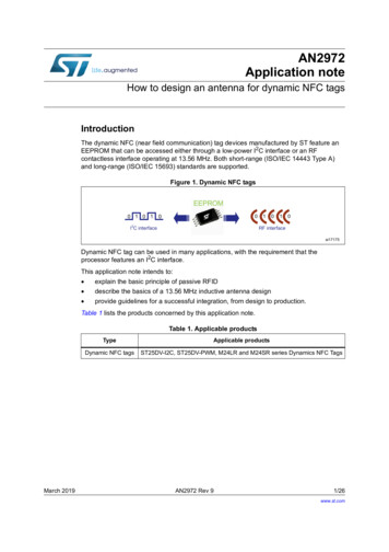
2therefore the following approximation as shown in (5) hasbeen made.PID CONTROLLER [5, 21]The PID controller is used to improve the dynamicresponse as well as to reduce or eliminate the steady-stateerror. The derivative controller adds a finite zero to theopen-loop plant transfer function and improves thetransient response. The integral controller adds a pole atthe origin, thus increasing system type by one andreducing the steady state-error due to a step function tozero.The continuous form of a PID controller, with inpute( ) and output u pid ( ) , is generally given as : 1u pid (t ) k p e (t ) Ti e (τ ) d τtt Td de (t ) dt (1)where kp is the proportional gain, Ti is integral timeconstant and Td is the derivative time constant. We canalso rewrite asu pid (t ) k p e (t ) k i e (τt0) dτ kdde (t )dt(2)where ki kp / Ti is the integral gain and kd kpTd is thederivative gain.In simple form, the PID controller transfer function isC(s ) kp ki ksds(3)BASIC PID SERVO MOTION SYSTEM [22]The basic components of a typical servo motionsystem are depicted in Fig. 1. According to this figure,the servo drive closed a current loop and is modeledsimply as a linear transfer function G(s). In their mostbasic form, servo drives receive a voltage command thatrepresents a desired motor current. Motor shaft torque, Tis related to motor current, I by the torque constant, Kτ asshow in (4).T Kτ I(4)G (s) (5)1The servomotor is modeled as a lump inertia, J, aviscous damping term, b, and a torque constant, Kτ. Thelump inertia term is comprised of both the servomotor andload inertia. It is also assumed that the load is rigidlycoupled such that the torsional rigidity moves the naturalmechanical resonance point well out beyond the servocontroller’s bandwidth. This assumption allows us tomodel the total system inertia as the sum of the motor andload inertia for the frequencies that will be control.The actual motor position, θ(s) is usually measuredeither by an encoder or resolver coupled directly to themotor shaft. Again, the underlying assumption is that thefeedback device is rigidly mounted such that itsmechanical resonant frequencies can be safely ignored.External shaft torque disturbances, Td are added to thetorque generated by the motor’s current to give the torqueavailable to accelerate the total inertia, J.Around the servo drive and motor block is the servocontroller that closes the position loop. A basic servocontroller generally contains both a trajectory generatorand PID controller. The trajectory generator typicallyprovides only position set-point commands labeled in Fig.1 as θ*(s). The PID controller operates on the positionerror and outputs a torque command that is sometimesscaled by an estimate of the motor’s torque constant, K̂ t .If the motor’s torque constant is not known, the PID gainsare simply re-scaled accordingly. Due to the exact valueof the motor’s torque constant is generally not known, thesymbol “ ” is used to indicate it is an estimated value incontroller. In general, equation (6) holds with sufficientaccuracy so that the output of the servo controller (usually /- 10 Volts) will command the correct amount of currentfor a desired torque.Kˆt K(6)tThere are three gains to adjust in the PID kp, ki and kd.These gains all act on the position error defined as (7).The output of the PID controller is a torque signal.error (t) θ*(t) - θ(t)(7)PERFORMANCE ESTIMATION OF PIDCONTROLLER [5, 23]Fig. 1: Basic P.I.D Servo Control Topology [22]For the purposes of this discussion, the transferfunction of the current regulator or really the torqueregulator can be approximated as unity for the relativelylower motion frequencies that are interested in andController design attempts to minimize the systemerror produced by certain anticipated inputs. The systemerror is defined as the difference between the desiredresponse of the system and its actual response.Performance criteria are mainly based on measures of thesystem error. Basically, PID controller design methodusing criterion as tabulate in TABLE I.
3changing the velocity of each particle toward its pbest andgbest locations at each time step. As example, the jthparticle is represented as xj (xj,1 , xj,2 , . . . ,xj,g) in the gdimensional space. The best previous position of the jthparticle is recorded and represented as pbestj (pbestj,1 ,pbestj,2 , . . . , pbestj,g). The index of best particle amongall particles in the group is represented by the gbestg. Therate of the position change (velocity) for particle j isrepresented as vj (vj,1, vj,2, . . . , vj,g). The modifiedvelocity and position of each particle can be calculatedusing the current velocity and distance from pbestj,g togbestg as shown in the following formulas:TABLE IPERFORMANCE ESTIMATION OF PIDCONTROLLER [23]Name of CriterionIntegral of the AbsoluteError (IAE)Integral of Square Error(ISE)Integral of Timeweighted Square Error(ITSE)Integral of Timeweighted AbsoluteError (ITAE)FormulaIAE e (t ) dt0 ISE e(t ) dt20ITSE 0te(t ) dt2 ITAE t e(t ) dt0A disadvantage of the IAE and ISE criteria is that itsminimization can result in a response with relatively smallovershoot but a long settling time because IAE and ISEperformance criterion weights all errors equallyindependent of time. Although the ITSE performancecriterion weights errors with time, the derivationprocesses of the analytical formula are complex and timeconsuming.In this paper, the performance criterion in the timedomain was used as proposed by [5] for evaluating thePID controller. A step of good control parameters kp, kiand kd can yield a good step response that will result inperformance criteria minimization in the time domain.These performance criteria in the time domain include theovershoot Mp, rise time, tr, settling time, ts and steadystate error Ess. Therefore, a new performance criterionW(K) is defined as [5]:W (K ) (1 e e β( β ) ) (M(t s tpr Ess))(8)where K is [kp, ki , kd] and β is the weighting factor.The performance criterion W(K) can satisfy thedesigner requirements using the weighting factor, β value.β can set larger than 0.7 to reduce the overshoot andsteady-state error or smaller than 0.7 to reduce the risetime and settling time.OVERVIEW OF PARTICLE SWARMOPTIMIZATION [5, 11, 13, 24]The particle swarm optimization (PSO) has beenintroduced by Kennedy and Eberhart in 1995. PSO isderived from the social-psychological theory, and hasbeen found to be robust in complex systems. Each particleis treated as a valueless particle in g-dimensional searchspace, and keeps track of its coordinates in the problemspace associated with the best solution (evaluating value)and this value is called pbest. The overall best value andits location obtained so far by any particle in the groupthat was tracked by the global version of the particleswarm optimizer gbest. The PSO concept consists ofv (jt, g1) w v (jt, )g c1 rand( ) ( pbest j , g c 2 rand x( ) (gbest g(t )j,g) x (jt, )g)(9)x (jt, g1) x (jt, )g v (jt, g1)(10)j 1, 2, , ng 1, 2, , mwherenmt (t )number of particles in a group;number of members in a particle;pointer of iterations(generations);v j,gvelocity of particle j at iteration t,v gmin v (j t, )g v gmax ;winertia weight factor;acceleration constant;c1, c2rand( ) random number between 0 and 1;x (jt, )gcurrent position of particle j at iteration t;pbestj pbest of particle j;gbest gbest of the groupmaxThe parameter v gdetermined the resolution, orfitness, with which regions were searched between themaxpresent position and the target position. If v gis toomaxhigh, particles might fly past good solutions but if v gistoo low, particles may not explore sufficiently beyondlocal solutions.The constant C1 and C2 represent the weighting of thestochastic acceleration terms that pull each particletoward pbest and gbest. C1 and C2 were often set to be 2.0according to past experience. This because low valuesallow particle to fly far from the target region beforebeing tugged back while high values result in abruptmovement toward or past target regions.Generally, the inertia weight w is set according toequation (11) below. Suitable selection of w provides abalance between global and local explorations, thusrequiring less iteration on average to find a sufficientlyoptimal solution.w w max w min iteriter max(11)where itermax is the maximum number of iterations orgenerations and iter is the current number of iterations.
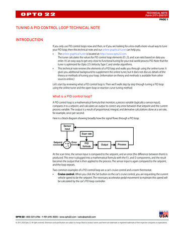
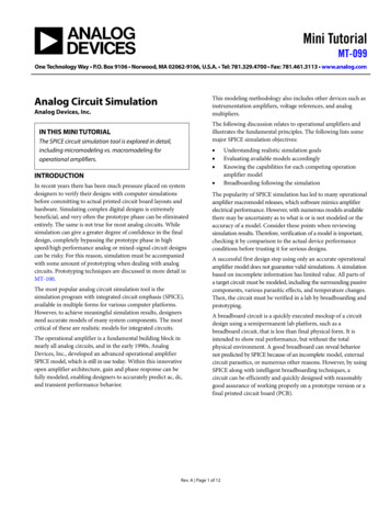
4IMPLEMENTATION OF A PSO-PID CONTROLLER[5, 13]The PID controller using the PSO algorithm wasdeveloped to improve the step transient response oftypical servo motion system. It was also called the PSOPID controller. The PSO algorithm was mainly utilized todetermine three optimal controller parameters kp, ki, andkd, such that the controlled system could obtain a goodstep response output.In this paper, to apply the PSO method for searchingthe controller parameter, we use the “individual” toreplace the “particle” and the “population” to define the“group”. The three controller parameters kp, ki, and kd,composed an individual K by K [kp, ki, kd]; hence thereare three members in an individual. These members areassigned as real values. If there are n individuals in apopulation, then the dimension of a population is n x 3. Aset of good control parameters kp, ki, and kd, can achieve agood step response and result in minimization ofperformance criteria in the time domain including thesettling time (ts) , rise time (tr), maximum overshoot (Mp)and steady state error (Ess). In the same time, we definedthe evaluation value, f as in (12) which is reciprocal of theperformance criterion W(K) as in (8).f 1W(K )(12)It employs the smaller W(K) the value of individual K, thehigher its evaluation function.In order to limit the evaluation value of eachindividual of the population within a reasonable range, theRouth-Hurwitz criterion must be utilized to test theclosed-loop system stability before evaluating theevaluation value of an individual. The feasible individualand small value of W(K) if the individual satisfied theRouth-Hurwitz criterion stability test applied to thecharacteristic equation of the system.The searching procedures of the proposed PSO-PIDcontroller were shown as follows [5, 24, 25]:Step 1: Specify the lower and upper bounds of the threecontroller parameters and initialize randomly theindividuals of the population including searchingpoints, velocities, pbests and gbest.Step 2: For each initial individual K of the population,employ the Routh-Hurwitz criterion to test theclosed-loop system stability and calculate thevalues of the four performance criteria in thetime domain, namely Mp, Ess, tr and ts.Step 5: Modify the member velocity v of each individualK according to (13)v (jt, g1) w v (jt, )g(* rand ( ) * (gbest c 1 * rand ( ) * pbest c2j 1 , 2 K n,Step 6:( t 1 )If v j , g V gj,gg)) k (j t, g) k(t )j,g(13)g 1, 2K 3, then v (jt, g1) VgmaxmaxIf v (jt, g1) V gmax, then v (jt, g1) VgmaxStep 7:Modify the member position of eachindividual K according to (14)k (j t, g 1) k (j t, g) v (jt, g1)such thatmin(14)k gmin k (j t, g 1 ) k gmaxwhere k g and k grepresent the lower and upperbounds, respectively, of member g of the individual K.For example, when g is 1, the lower and upper bounds ofminmaxthe kp controller parameter are k g and k g respectively.maxStep 8: If the number of iterations reaches the maximumthen, go to Step 9. Otherwise, go to Step 2.Step 9: The individual that generates the latest gbest is anoptimal controller parameter.SIMULATION EXAMPLES RESULTSThe simulation of the Typical Servo Motion Systemwithout PID controller, PSO-PID controller and Zieglerand Nichols-PID Controller were implemented byMATLAB Version 7.2 and executed on the Pentium 42.66GHz personal computer with 1GB RAM.Typical Servo Motion System without PID ControllerThe block diagram of the Typical Servo Motion Systemwithout PID is shown in Fig. 2 below. Result of this stepresponse of the Typical Servo Motion System withoutPID controller has shown in following Fig. 3. To simulatethis case, we found that performance criteria of the systemin the time domain as the TABLE II below.Step 3: Calculate the evaluation value of each individualin the population using the evaluation value, fgiven by (12).Step 4: Compare evaluation value of each individual withits pbest. The best evaluation value among thepbest is denoted as gbest.Fig. 2: Block Diagram of the Typical Servo MotionSystem without PID Controller
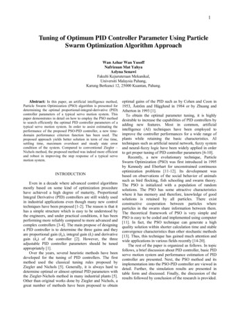
5Fig. 4: Block Diagram of the Typical Servo MotionSystem with PSO-PID ControllerFig. 3: Step response of the Typical Servo Motion Systemwithout PID controllerTABLE IIPERFORMANCE CRITERIA OF TYPICAL SERVOMOTION SYSTEM WITHOUT PID CONTROLLERPerformance CriteriaValueSettling time (ts)3.91 sRise time (tr)0.0070 sMaximum overshoot (Mp)97.7578 %Steady state error (Ess)0Fig. 5: Step response of the Typical Servo Motion Systemwith PSO-PID controller with β 1.0Typical Servo Motion System With PSO-PID ControllerAccording to the trial, the following PSO parameters areused for verifying the performance of the PSO-PIDcontroller in searching the PID controller parameters: the member of each individual is kp, ki and kd; population size 25; inertia weight factor w is set by (11), where wmax 0.9 and wmin 0.4; Range of three controller parameter:o kp : minimum value 0 ,maximum value 1.50;o ki : minimum value 0 , maximum value 1.00;o kd: minimum value 0 , maximum value 1.00; The limit of change in velocity :V kmax k pmax / 2opmaxo V k k imax / 2io V kmax k dmax / 2d Acceleration constant C1 and C2 2The block diagram of the Typical Servo Motion Systemwith PSO-PID controller is shown in Fig. 4 below.Results of this step response of the Typical Servo MotionSystem with PSO-PID controller with β 1.0 and β 1.5has shown in following Fig. 5 and Fig. 6 respectively. Thesimulation results that showed the best solution weresummarized in the Table III below.Fig. 6: Step response of the Typical Servo Motion Systemwith PSO-PID controller with β 1.5TABLE IIIBEST SOLUTION OF TYPICAL SERVO MOTIONSYSTEM WITH PSO-PID CONTROLLER WITH THEDIFFERENT VALUES OF Β1.01.5β2525Number 13.387611.6415Evaluation Value
6As can be seen, through about 25 iterations orgenerations, the PSO method can prompt convergenceand obtain good evaluation value, thus achieve betterperformance criterion that are rise time, settling time,percentage of overshoot and steady state error condition.These results show supremacy of the PSO-PID controllerthat can search optimal PID controller parameter quicklyand efficiently.Typical Servo Motion System with Ziegler and NicholsPID ControllerFig. 7: Determining fo and Ko of Ziegler and NicholsmethodIn order to emphasize the advantages of the proposedPSO-PID controller, we also implemented the Ziegler andNichols-PID Controller into the Typical Servo MotionSystem. The Ziegler and Nichols method basically boilsdown to these two steps (fundamental of servo motor):Step 1: Set ki and kd to zero. Excite the system with astep command. Slowly increase kp until the shaftposition to oscillate. At this point, record thevalues of kp and set ko equal to this value. Recordthe oscillation frequency, fo. Fig. 7 shows theresult of slowly increasing on the proportionalterm. The system begins to oscillate atapproximately 0.5Hz (fo 0.5Hz) with koapproximately 5e-5 Nm/radStep 2: Set the final PID gains using equation (15)k p 0.6 k 0 Nm/rad ;k i 2 f o k p Nm/(rad.sec) ;kd kp(15)Nm/(rad.sec) ;8 foUsing the values got in Step 1 into the equation (15),the optimum PID gains according Ziegler and Nicholsmethod are then:-4kp 3.0e Nm/radki 3.0e-4 Nm/(rad.sec)kd 7.40e-5 Nm/(rad.sec)Fig. 8 shows the result of Typical Servo Motion Systemwith Ziegler and Nichols-PID Controller. Table IVsummarize the performance criteria of the system in thetime domain.Fig. 8: Step response of the Typical Servo Motion Systemwith Ziegler and Nichols-PID ControllerTABLE IVPERFORMANCE CRITERIA OF TYPICAL SERVOMOTION SYSTEM WITH ZIEGLER AND NICHOLSPID CONTROLLERPerformance CriteriaValueSettling time (ts)4.3980 s0.5160 sRise time (tr)34.2869 %Maximum overshoot (Mp)Steady state error (Ess)0DISCUSSION AND CONCLUSIONThis paper presents a novel design method fordetermining the PID controller parameters using the PSOmethod. The proposed method integrates the PSOalgorithm with the new time-domain performancecriterion into a PSO-PID controller. Through thesimulation of a typical servo motion system, the resultsshow that the proposed controller can perform an efficientsearch to obtain optimal PID controller parameter thatachieve better performance criterion that are rise time,settling time, percentage of overshoot and steady stateerror condition.This PSO-PID controller has been compared ZieglerNichols PID method to verify it being more superior .Thecomparison from rise time show that the PSO-PIDachieves less time that is 0.01sec compared to ZieglerNichols PID that need 0.52sec. The system using ZieglerNichols method takes about 4.4sec to finally settlebetween 2% of the final value making it very difficult toincorporate into any high performance motion control
7application. In contrast, the PSO method gives a quickersettling time that it takes only 0.02sec to settle. The PSOmethod instantaneously reduces the maximum overshootof the system to only 0.1% compared to the ZieglerNichols method that recorded 34.3% of maximumovershoot. However, there is no steady state error for bothmethods.Therefore, it is clear from the results that the proposedPSO method has more robust stability and efficiency andcan solve the searching and tuning problems of PIDcontroller parameters more easily and quickly than theZiegler-Nichols method.REFERENCES[1] Pedret, C., Vilanova, R., Moreno, R. and Serra, I. (2002). Arefinement procedure for PID controller tuning. Computerand Chemical Engineering, Vol.26, 903-908.[2] Chang, W.-D., Hwang, R.-C. and Hsieh, J. –G. (2003). Amultivariable on-line adaptive PID controller using autotuning neurons. Engineering Applications of ArtificialIntelligence, Vol.16, 57-63.[3] Tan, K.K., Huang, S. and Ferdous, R. (2002). Robust selftuning PID controller for nonlinear systems. Journal ofProcess Control, Vol.12, 753-761.[4] Valério, D. and Costa, J. S. (2006). Tuning of fractionalPID controllers with Ziegler-Nichols-type rules. SignalProcessing, Vol. 86, 2771-2784.[5] Gaing, Z.L. (2004). A Particle Swarm Optimizationapproach for optimum design of PID controller in AVRsystem. IEEE Transactions on Energy Conversion,Vol.19(2), 384-391.[6] Chen, M. and Linkens, D.A. (1998). A hybrid neuro-fuzzyPID controller. Fuzzy Sets and Systems, Vol.99, 27-36.[7] Chu, S.-Y. and Teng, C.-C. (1999). Tuning of PIDcontrollers based on gain and phase margin specificationsusing fuzzy neural network. Fuzzy Sets and Systems, Vol.101, 21-30.[8] Lan, L. H. (2006). Stability analysis for a class of TakagiSugeno fuzzy control systems with PID controllers.International Journal of Approximate Reasoning, In Press.[9] Kim, S.-M. and Han, W. Y. (2006). Induction motor servodrive using robust PID-like neuro-fuzzy controller. ControlEngineering Practice, Vol.14, 481-487.[10] D’Emilia, G., Marra, A. and Natale, E. (2006). Use ofneural networks for quick and accurate auto-tuning of turing, In Press.[11] Kennedy, J. and Eberhart, R.C. (1995). Particle swarmoptimization. Proceedings of the International Conferenceon Neural Networks, 1942-1948.[12] Fan, H. (2002). A modification to particle swarmoptimization algorithm. Engineering Computations, Vol.19, 970-989.[13] Kao, C. –C, Chuang, C.-W and Fung, R. –F (2006). Theself-tuning PID control in a slider-crank mechanism systemby applying particle swarm optimization approach.Mechatronics, Vol.16, 513-522.[14] Tayal, M. (2003). Particle swarm optimization formechanical design. M. Sc. thesis, The University of Texasat Arlington, United States.[15] Wang, K.-P., Huang, L., Zhou, C. –G. and Pang, W.(2003). Particle swarm optimization for traveling oblem. Proceedings of the 2nd International Conferenceon Machine Learning and Cybernetics, 1583-1585.Ahmed, T. (2004). Adaptive particle swarm optimizer fordynamic environments. M. Sc. thesis, The University ofTexas at Arlington, United StatesBaumgartner, U., Magele, Ch. and Renhart, W. (2004).Pareto optimality and particle swarm optimization. IEEETransactions on Magnetics, Vol. 40( 2), 1172-1175.Ning, L., Fei, L., Debao, S. and Chang, H. (2004). Particleswarm optimization for constrained layout optimization.Proceedings of the 5th World Congress on IntelligentControl and Automation, 2214 -2218.Nunez, J.J.J. (2004). Particle swarm optimizationapplications in power system engineering. M.Sc. thesis,University of Puerto Rico, Mayagues Campus, Puerto Rico.Asokan, P., Baskar, N., Babu, K., Prabhaharan, G. andSaravanan, R. (2005). Optimization of surface grindingoperations using particle swarm optimization technique.Journal of Manufacturing Science and Engineering, Vol.127, 885-892.Chang, W.-D. and Yan, J.-J. (2005). Adaptive robust PIDcontroller design based on a sliding mode for uncertainchaotic systems. Chaos, Solitons and Fractals, Vol. 26,167-175.Kaiser, D., Fundamentals of Servo Motion voFundamentals.pdfWang, X., Wang, Y., Zhou, H. and Hui, X. (2006). PSOPID: A novel controller for AQM Routers. Proceedings ofIEEE and IFIP International Conference on Wireless andOptical Communication Network (IEEE/IFIP WOCN2006), 1-5.Yoshida, H., Fukuyama, Y., Kawata, K., Takayama, S. andNakanishi, Y. (2001). A Particle Swarm Optimization forreactive power and voltage control considering voltagesecurity assessment. IEEE Transactions on Power Systems,Vol.15(4), 1232-1239.Liu, Y., Zhang, J. and Wang, S. (2004). Optimizationdesign based on PSO algorithm for PID controller.Proceedings of 5th World Congress on Intelligent Controland Automation, Vol. 3, 2419-2422.
Tuning of Optimum PID Controller Parameter Using Particle Swarm Optimization Algorithm Approach Wan Azhar Wan Yusoff Nafrizuan Mat Yahya Azlyna Senawi Fakulti Kejuruteraan Mekanikal, Universiti Malaysia Pahang, Karung Berkunci 12, 25000 Kuantan, Pahang. Abstract: In this paper, an artificial intelligence method,