Transcription
Basic Installation Instructions for:ididit’s Universal Tilt Columnswww.ididitinc.comWhat’s inside this installation booklet: U-Joint & Shafting Installation Lever Installation Wiring your Column Synchronizing your Column Additional Notes Accessory & Add-On Checklistididit is.Your Steering Column SpecialistFor #’s1120120010, 1120160010, 1120280010, 1120300010, 1120320010, 11203500101520120010, 1520160010, 1520280010, 1520300010, 1520320010, 15203500101120120020, 1120160020, 1120280020, 1120300020, 1120320020, 11203500201520120020, 1520160020, 1520280020, 1520300020, 1520320020, 15203500201120120051, 1120160051, 1120280051, 1120300051, 1120320051, 11203500511520120051, 1520160051, 1520280051, 1520300051, 1520320051, 15203500511030120030, 1030160030, 1030280030, 1030300030, 1030320030, 10303500301030120040, 1030160040, 1030280040, 1030300040, 1030320040, 1030350040ididit inc. 610 S. Maumee St. Tecumseh, MI 49286PH: 517-424-0577 FAX: 517-424-7293Revised 3/19/2010Instruction # 8000000020
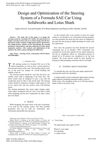
Thank you for purchasing an ididit steering column!We will first give you an overview of mounting the steering column in themost common street rod or hot rod applications. The steering column must besupported at the dash and where it protrudes through the firewall. It is important that the steering column is tight and secure. There is a shorty applicationwhich will use two drops under the dash, with the supportbearing through the firewall (since the column ends underthe dash). To attach your column to the steering gear box,a u-joint is attached to the column, a shaft is attached tothe u-joint, and that shaft will lead down to a u-joint connected to the gear box (or rack).It is highly recommended that you test fit your steeringcolumn before painting the column. Test fitting now will save you a headache later on. We are not responsible for paint.U-Joint Installation:For proper installation of u-joints and couplers on your column, follow manufacturers recommendations, but in general, two basic styles used on your ididit,inc. steering column:DD Output Shaft (our most common shaft):Double “D” output shafts are either 1” or 3/4” diameter. Mostu-joint manufacturers use two setscrews to fasten the u-jointto a DD shaft. These two set screws are positioned 90 degreesfrom each other. To install a u-joint over the shaft simplyslide the u-joint over shaft until it is fully engaged in the joint(Borgeson Universal recommends 7/8” – 1” engagement). Usea marker to make a mark through each hole in the joint. Remove the joint.Using a quarter inch drill bit, spot the shaft where the setscrews will seat. Reinstall the joint and install setscrews and jam nuts. (Note: all joint mfg’s recommend using a thread-locking compound on setscrew and nut).Spline Output Shaft:Spline output shafts are either 1” 48 or 3/4” 36. To install youru-joint simply slide the u-joint over the spline, taking care toline one set screw up with the flat spot on the shaft. If the shafthas no flat spot, slide the joint on so the shaft is fully engagedin the joint (Borgeson Universal recommends 7/8” – 1” engagement). Use a marker to make a mark through hole in thejoint. Remove the joint. Using a quarter inch drill bit, spot the shaft where thesetscrew will seat. Re-install the joint and install setscrew and jam nut. (Note:all joint manufacturers recommend using a thread-locking compound on setscrew andnut).1
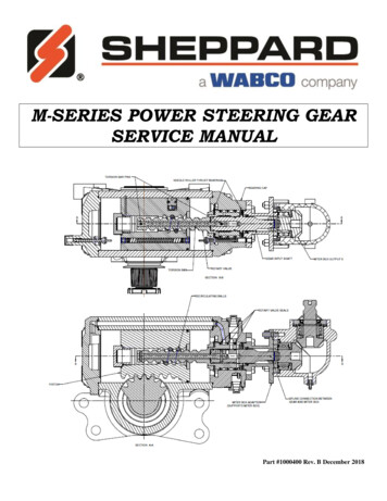
How to install your Tilt, Turn Signal Levers and Hazard KnobTurn Signal Lever:The signal lever is the lever closest to the topof the column. With the steering wheel andadaptor removed, look down from the topof the column and you’ll see where a singlescrew holds the signal lever in place. Insert thenew lever using the provided screw into roundhole (not D shaped hole). When installing thislever in a new column, use the screw suppliedto fasten the lever in the recessed area on thesignal switch arm.Tilt Lever:Look directly below the turn signal lever, andyou’ll see another opening in the column. Insidethis opening is a threaded hole which the new leverscrews into.Emergency Flasher Knob:Almost directly opposite the turn lever on the steering column is another opening. Inside this opening is a hole in the nylon switch. Simply screw thenew knob in place (clockwise). When completinginstallation of flasher knob make sure that the knobis in the out (off), position so when finished wiringyou don’t have any complications.If Column Shift Application:Place column shift knob onto the shift lever.Once your lever is on, use setscrew (provided)and adjust knob so set screw is not facing forward, tighten setscrew. Do not remove the upper shift lever for any reason! The tension springwill pop out and it is very difficult to re-install.2
Wiring your ColumnThis ididit steering column uses a standard 3 7/8-inch male connect. However, some GM columns use a 4 ¼-inch male connector. Connectors donot interchange and must be used in pairs. A mate to the 3 7/8 inch plug isavailable through ididit. If you need to change this connector for any reasonthe following schematic will be helpful.Horn Button Wiring:A horn may require two wires to properly function with an ididit column. The center lug onthe button should connect to a horn wire, whichis provided by ididit with your steering column.This horn wire will slide into the horn cam (whiteplastic tube sticking up on the top of the column).If there is a second wire off to the side it is probably a ground wire (check with the horn buttonmanufacturer to be sure). This is normally used when an o-ring is used tohold the button in place. The o-ring does not provide sufficient ground,therefore, an additional wire is provided to ground the horn button. If thereis not a hole in adaptor to ground to, use one of the puller holes with a shortbolt to attach the wire to the adaptor.Synchronizing your ColumnIn order to insure proper functioning, this steering column must be installed in sync with the rest of the steering system. Turn signal cancellationand wheel position, as well as smooth steering operation depends on it.Although not all of them may need adjustment, the complete table of stepsrequired for full synchronization is as follows (continued on next page):3
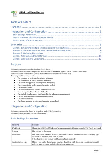
1. The front wheels must be pointing straight forward with the steeringtoe set reasonably close.2. Rotate the input shaft of the gearbox or rack from lock to lock and setthe box exactly half way between. For example, if the shaft rotatesthree full turns from lock to lock. The center will be at 1½ turns fromeither locked position.3. Install the steering arm and drag link, and adjust tie rod ends to get thedrag link to fit without moving either the box/rack or the front wheels.Rotating each tie rod end the same number of turns will preserve adjustment.4. With the column mounted in position and two joints are used on ashaft, the forks of the yokes closest to each other should be in line,or “in phase”. Premature wear orbinding can result if the u-jointsare not phased properly. Sometimes if the u-joints are at a severe angle, even if they are phased correctly, a hard spot in the steering may occur for no apparent reason. Ifthis happens, index the u-joints two or three splines in one direction.The hard spot should disappear or be minimized.5. Install the shaft or joint on the gear box/rack. Leave the upper part ofthe shaft unconnected for the time being.6. Position the column housing so that the signal switch arm is level tothe left hand side.7. Install the column through firewall, into your joint.8. To achieve proper synchronizing of your column the finished installation of your columnshould look like the column diagram below. Ifpost on horn cam is not at10:30, grasp post and turnit until it is at 10:30. Oncecompleted, your columnnow is in sync.4
IMPORTANT!!Steering Wheels:The top shaft of the column is the same as aGM passenger car from 1969-94 (Van columns& some truck columns are not the same as passenger cars). Original wheels from these yearswill bolt directly to the top of the column with nomodifications. An aftermarket wheel will requirean adaptor. Align the spline and horn cam on thetop of the column with those in the adaptor and slide it onto the column. Anut has been provided with your steering column. The nut will secure thewheel to the top of the column. The nut on the wheel should be torqued to40 ft lbs.Column Shift Linkage Installation:At the bottom of your column you will notice alever. This is the shift lever where your linkagewill attach from the column to the transmission. Note the 5/16 hole through the bushings,most kits use a 5/16 bolt to secure the rod tothe column. Please follow the kit instructionsfor the linkage, but make sure that no part oftheir kit hits the metal portion of the lever, asit will create a rattle in the column.STILL CAN’T GET IT?ididit inc. has been serving the rodding community for over 20 years andone of the major factors has always been our excellent customer service.If you still can’t get it and you have tried everything on these pages feelfree to call us at (517) 424-0577, Monday-Friday from 8:30a-5:30p andSat. 10:00a-2:00p Eastern Standard Time. You can also email us at tech@ididitinc.com5
Think you may have forgotten something?Here’s what you may have missed:Add Ons: (Add Ons should be installed on the column prior to shipment) Cruise Control: Carbureted Engine or Fuel Injected Engine? Dimmer or Wiper: Dimmer/Wiper Kits will replace the original knobs and leversthat come standard on an ididit column. This is a replacement lever with a push button at the end of the knob. The Dimmer/Wiper kit when pushed is either On or Off.Includes relay kit.Accessories: Steering Wheel: We cannot recommend any brand of wheel because there are somany to choose from. If you are having a hard time figuring out if a wheel you hadpurchased will work with an adaptor or an ididit column, simply give us a call. Steering Wheel Adaptor: Unless using original 1969 & Up Steering Wheel youwill need an adaptor. The adaptor may depend on the wheel. ididit recommends purchasing the Steering Wheel prior to purchasing the adaptor. 3, 5, 6 or 9-Bolt Adaptorsare Available with finishes of Chrome, Black Powder Coated, Brushed or PolishedAluminum. The adaptors are available with or without Horn Buttons. Under dash Mount (A.K.A. Column Drop): A solid under dash mount is very necessary when installing your steering column. ididit offers several variations of underdash mounts for Floor Shift & Column Shift Columns. When measuring for yourcolumn drop, measure from the center of the column to the dash (see diagram). Floor Mount: Like the under dash mount this piece is very necessary when installing your steering column safely. ididit offers a Classic Floor Mount, Swivel Ball FloorMount, Adjustable Floor Mount with or without a trim piece. Available for any ididitSteering Column. Shift Indicator: Shift indicators available are 3 or 4-speed transmissions. ididitalso carries shift indicators for Ford AOD & AODE transmissions. The indicators areacrylic and can be ordered with or without the housing. The housing finishes include:Chrome, Black Powder Coated, Brushed or Polished Aluminum. Accessory Knobs for Levers or Dash: Deco or Retro knobs are available to replace the standard knobs that come standard on the column or if you plan on matchingthose knobs to your dash knobs. Deco knobs are only available in Polished Aluminum.Standard and Retro Knobs are available in Chrome, Black Powder Coated, Brushedor Polished Aluminum. Cable Shift Linkage Kit: Kits are available for Ford C-4, C-6 & AOD, GM Transmission (350, 400, 700R4, 200R4, 4L60 & 4L80), and Chrysler 727 & 904 Transmissions. Early power glide kits are not available, however later power glide kits are.6
No part of this guide may be reprinted, reproduced or utilized in anyform without the express written permission of ididit, inc.2009 ididit, inc.All Rights ReservedPrinted in the USAididit,inc.610 S. Maumee St., Tecumseh, MI 49286(517) 424-0577 (517) 424-7293 faxwww.ididitinc.com
7. Install the column through firewall, into your joint. 8. To achieve proper synchronizing of your column the finished instal-lation of your column should look like the col-umn diagram below. If post on horn cam is not at 10:30, grasp post and turn it until it is at 10:30. Once completed, your column now is in sync. 4