Transcription
Inside the GM TiltSteering ColumnBy: JAZZMANThe first time I got into a GM tilt column (or any column for that matter) was when the column in my trusty old'84 Phoenix got so wobbly that it was scaring me to drive the car. It took me most of a day to repair that columnbecause the factory service manual was terrible, and because I had to figure out how to design and fabricate allthe special tools using junk I had on hand. Now, with the benefit of nearly 30 columns repaired over the last fewyears, I can do the same repair in the car in around an hour to an hour and a half on average, with my best timebeing just under 40 minutes. I've been wanting to do this topic for a couple years now, and decided that it wastime.I debated with myself what would be the best way to explore the Saginaw tilt column as used in the Fiero andmost other GMs of that era, and concluded that a ground-up assembly would be the most effective. My intentwith this topic is to give an in-depth working knowledge of GM tilt columns to anyone interested in their innerworkings. I'm also going to create a separate topic that will detail the classic wobbly column repair proceduresince it won't require the same level of disassembly as this build did.To make the pictures more useful I painted some parts to make them more visible, and more importantly, didcutaways to allow a better view of the complex pivot point component relationships and other hidden details.For clarity I also cleaned and degreased most parts that would normally be lubricated, so if you're using thistopic as a guide for overhauling a column it is important that all sliding/contact points are lubricated with a goododorless waterproof grease that won't run when hot.The column shown is for a manual transmission equipped Fiero as indicated by the key release lever. Automaticcolumns use a different ignition switch that has a provision for an interlock cable that runs to the shiftermechanism. I will detail the internal differences between the two types of columns during the build.Inside the GM Tilt Steering Column Page 1
Inside the GM Tilt Steering Column Page 2
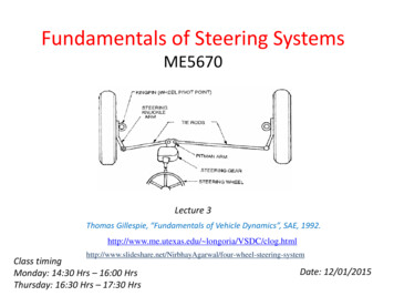
Here are all of the tools necessary for working on the GM tilt column. Note, some tools aren't required for thisbuild:Steering wheel puller (disassembly only), either two-hole for stock wheels or three-hole for most aftermarketwheelsLock plate compressor (Autozone carries the one pictured for the best price I've found)Needle nose pliersSnap ring pliers, outside type (safety snap ring)20mm or 13/16" deep socket (steering wheel nut)7mm socket or nutdriver (trim panel screws under dash)11mm socket (column shaft pinch bolt to intermediate shaft at floorboard)13mm socket (column bracket to column bolts )15mm socket (column bracket to dash support bolts)1/4" socket or nut driver (lock pin spring, bottom bearing assembly)2 small flat blade screwdriversSmall Phillips screwdriverMedium Phillips screwdriverT-20 Torx bit or driver ('86-up ignition lock cylinder retaining screw)T-30 Torx bit or driverPivot pin puller (can make one, risky though) (disassembly only)E-8 Torx head socket (can substitute 1/4" 6-point socket)5/16" socket or nut driver (ignition & high beam switches)3/8" socket or nut driver (ignition & high beam switches)Adjustable and/or regular wrenches for the steering wheel & pivot pin pullersInside the GM Tilt Steering Column Page 3
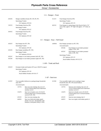
Technically, all of the Phillips-head looking screws are actually Pozidriv head, but Phillips drivers will work justfine for occasional use. You'll also note that a combination of metric and SAE fasteners are used. This is becausethe Saginaw plant where the columns were built still used SAE tooling whereas the GM assembly plants wherethe columns were installed were fully metric. Thus, the internal fasteners in the column are SAE and thefasteners that connect it to the vehicle are metric.Here are all of the parts in a GM tilt column, excluding the steering wheel:Inside the GM Tilt Steering Column Page 4
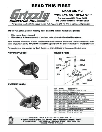
We start assembly with the core part, the column jacket assembly:This is the lower bearing with dust shield and ( 2 ) 8-32 x 1" self-tapping deformed-thread screws:Inside the GM Tilt Steering Column Page 5
Install the lower bearing assembly and dust shield into the tail of the column jacket using a 1/4" socket. It isindexed so that it can only go in one way:Now it's time to move to the top of the column jacket. Note the various slots and other features:Inside the GM Tilt Steering Column Page 6
Here's the lower housing shroud. I cut away the side so that during the assembly it will be easier to see how thevarious components relate to each other:The lower housing shroud simply slides onto the end of the column jacket, there are guides that allow it to onlyfit one way. When it is fully seated you'll see that the guides are below the large slot. Note the bump on the rightside, that is for the manual column key release lever. The automatic column's lower housing shroud doesn't havethis bump:Inside the GM Tilt Steering Column Page 7
Here is the lower housing bolting plate. As a side note, my theory as to why the four bolts work lose and causethe "wobbly column" pattern failure so common with GM tilt columns is that the cross-sectional area of the tubethat the bolting plate bears against is too small, resulting in the thin column tube edges deforming over time.This releases the tension that holds the bolts in place and once that occurs they rapidly back out under thevarious cyclic loads to which the steering column is subjected. You can see how little contact area there is asevidenced by the four narrow shiny spots around the edges:Inside the GM Tilt Steering Column Page 8
You can see that the bolt spacing is wider at the top than at the bottom. Install the bolting plate by inserting itinto the tube sideways, tilting the right side tab into the large slot, then bringing the plate up flat and insertingthe two small tabs on the left into their corresponding slots in the tube wall:Inside the GM Tilt Steering Column Page 9
On a manual column the next parts to install are the key release lever and spring:Inside the GM Tilt Steering Column Page 10
They fit into an annular groove in the lower shroud, with the spring free end inserting into its pocket first as thelever is pushed into place:Inside the GM Tilt Steering Column Page 11
Next up is the lower housing assembly. This has the pins that the tilt locking pawls engage to hold the tiltadjustment, and on manual columns it also has the key release lever guide as shown in the second photo below.The guide holds the manual key release lever in the shroud. The only difference between the manual and autolower housing is the presence of the guide:The high beam switch pushrod:Inside the GM Tilt Steering Column Page 12
Install the high beam pushrod into the lower housing:Install the ignition switch pushrod. It is installed by running the rod end down through a slot in the shroud (inthe portion of the shroud that was cut away for this build topic):Inside the GM Tilt Steering Column Page 13
Position the lower housing in place with the ignition switch and high beam pushrods routed as shown. Note,though it is possible to install the high beam pushrod after installing the housing, it is not possible to install theignition switch pushrod after the housing is bolted in place:The lower housing is held onto the column by four Torx-head bolts that screw into the bolting plate:The bolts use an E8 socket, but can also be tightened with a 1/4" 6-point socket or a 6mm 6-point socket.Locktite is probably not a bad idea on the threads:Inside the GM Tilt Steering Column Page 14
We're ready to install the ignition switch. There is a pocket in the side of it that the pushrod fits into:Here's how the pushrod looks inserted into the switch:Inside the GM Tilt Steering Column Page 15
The ignition switch bolts to the column with a 5/16" stud-headed screw. Install the screw finger tight at thistime, note the slots that allow the ignition switch to be adjusted up or down the column:We'll adjust the ignition switch later, after the column is fully assembled.Inside the GM Tilt Steering Column Page 16
Next, install the high beam switch. It is held in place by a 3/8" nut on the stud-headed screw and a 5/16" screwthat also holds the ignition switch in place. As with the other bolt, leave the nut and bolt finger tight at this time:It is ok to wait and install the ignition and high beam switches last after the rest of the column is completelyassembled, but I like to do it early because it makes it easier to hold the ignition switch and high beam pushrodsin place while installing the upper housing assembly. This is where we should be at this point:Here's the main shaft assembly:Inside the GM Tilt Steering Column Page 17
One of the main safety features of the steering column is that this shaft assembly is collapsible. This is done byusing a telescoping tube design with an injection-molded plastic key to lock the tube and shaft together:This plastic key will shear when the torso hits the steering wheel during a severe collision, allowing the shaft tocollapse into the tube instead of punching your heart out through your spine. When a column is dropped on itsend or a hammer is used to knock the steering wheel loose this is the part that is typically damaged, causing thecolumn to rattle over bumps and sometimes feel like it has slack with a "click" feeling. Once this happens theshaft is considered non-repairable.The main shaft connects to the stub shaft with a plastic ball joint that contains a spring to remove play:Inside the GM Tilt Steering Column Page 18
Insert the ball assembly into the stub shaft sideways, then rotate ninety degrees to lock it into place:Inside the GM Tilt Steering Column Page 19
Insert the main shaft "C" into the ball at a ninety degree angle, there's a slot in the stub shaft for this, thenstraighten the two shafts until they are aligned, thus locking the shafts together at the ball joint. There should bestrong friction as the shafts are aligned and no play when you are done. The spring between the ball halvespushes them apart, taking the slack out of the ball joint.Insert the shaft assembly into the tube and out through the lower bearing.The upper housing contains most of the bits of the column. We'll start by installing the ignition lock cylindercross shaft and gear.Inside the GM Tilt Steering Column Page 20
Here is the ignition lock cylinder cross shaft and sector drive gear:Insert the longer flat end through the upper housing and then into the gear. Orient the gear as shown:Use a socket to support the gear and gently tap the cross shaft through until it seats fully in the gear. The gearshould rotate freely:Inside the GM Tilt Steering Column Page 21
The end of the shaft will protrude slightly, just far enough to expose the notches on the edges of the shaft:Next, install the sector preload spring, it simply pushes into place in the bottom of the sector guide in thehousing:Inside the GM Tilt Steering Column Page 22
The upper housing also contains the upper and lower bearings for the stub shaft. When turning the steeringwheel these bearings are what keep the wheel feeling "tight" as it rotates. The bearing balls are equally spaced inthe upper housing by slotted retainers. Use grease to hold the balls in the retainers, then set the retainers into theraces using more grease to hold them in place. The following pictures show the upper and lower bearingsinstalled, with the tilt release lever installed for visual reference.This is looking at the upper bearing:And the lower bearing:Inside the GM Tilt Steering Column Page 23
Here is the lock pin, this pin engages the notches in the edge of the lock plate and locks the steering wheel whenthe key is turned to the LOCK position:Insert the lock pin into the upper housing as shown. Note how the groove on the bottom of the pin engages abump on the gear:Install the sector into the upper housing. Rotate the gear until the large tooth is pointed down and back, theninsert the sector from the rear such that the large tooth engages the large notch of the sector. This is what itshould look like with sector and lock pin installed:Inside the GM Tilt Steering Column Page 24
Next will be the hardest part for most people, so I'll devote extra pictures and explanations of the partsrelationships to help with this task. I'll begin with a brief description of how the various linkages work throughthe pivot point.The ignition lock cylinder turns a cross shaft that goes through the column and into a gear. The gear engages arack on the sector that moves up and down the column as the key is turned. The sector has an arch on the lowerend that fits between two pins at the top end of the ignition switch pushrod which in turn goes down the lengthof the column to where it connects to the actual ignition switch. The arch stays connected to the ignition switchpushrod as the sector rotates about the tilt pivot pin when the column is tilted, without moving the pushrod. Thepushrod pulls up as the key is turned toward the START position, and pushes down as the key is turned to theOFF position.The high beam linkage is different, its pushrod goes past the tilt pivot pin and through the upper housing, thenbends up into an arc. There is a curved follower that pushes against the arc of the pushrod, that follower in turnis pushed by the wiper switch which rotates on a pin when the turn signal stalk is pulled back. The curvedbottom of the follower slides along the arc of the pushrod as the column is tilted up and down.Here is the ignition sector, showing the inside with the arch at the right end and the rack at the left end:Here's the high beam follower:Inside the GM Tilt Steering Column Page 25
Here's a closeup view of the upper end of the ignition pushrod showing the two pegs:Here are detailed views of how the sector and follower engage the two pushrods in various degrees of tilt. Notehow the arched edge of the sector stays engaged between the two pegs on the aluminum molding at the top ofthe ignition switch pushrod, and how the high beam follower matches the arc of the end of the high beam switchpushrod:Inside the GM Tilt Steering Column Page 26
The tilt adjustment is maintained by toothed pawls that engage the pins in the top of the lower housing. Whenthe tilt release lever is pulled it releases the pawls and allows the upper column to pivot up and down on the tiltpivot pins. The notches in the two pawls are offset 1/2 tooth from each other, this allows the column tilt to adjustin 1/2 tooth increments. Only one pawl is ever engaged with a pin at a time. Here's a pic of the pawls in thereleased position:Inside the GM Tilt Steering Column Page 27
Now to assemble the upper housing assembly to the lower portion of the column. There are several things thatneed to be accomplished simultaneously while installing the upper housing assembly. The ignition sector needsto properly engage the pegs on the ignition switch push rod, making sure that the pushrod end fits into thegroove in the side of the lower housing. The high beam pushrod needs to be properly located through the lowerleft quadrant of the upper housing, the tilt pawls need to properly engage the pins in the top of the lowerhousing, and the pivot pin holes need to be aligned. On manual columns the key release lever slot needs toengage the pin sticking out of the top of the ignition pushrod. Also, the lock pin needs to stay properly engagedas it tends to fall out during this step. Though this is the most intimidating part of the build, it's actually not ashard as it sounds. One helpful tip is to keep the stub shaft pulled toward you as you maneuver the upper housinginto place, this will help keep the balls in the lower race from being accidentally dislodged during this part of theassembly process.Start by pulling the ignition switch pushrod all the way up toward the top of the column. Pull the high beamswitch pushrod up, but not past the bend in the rod. Insert the stub shaft into the back of the upper housingassembly as you bring the housing assembly toward the lower housing. Rotate the upper housing assemblyclockwise about 1/4 turn, this should be enough to allow working the upper end of the high beam pushrodthrough the large hole in the lower left quadrant of the upper housing assembly. It is assumed that the tilt lever isinstalled at this point.Inside the GM Tilt Steering Column Page 28
Once the upper end of the high beam pushrod is properly placed, rotate the upper housing counterclockwise asyou bring it closer to the lower housing. Rotate the ignition cross shaft as needed to extend the arched end of thesector, then engage the arched end of the sector with the upper end of the ignition switch pushrod. Make surethat the arched end fits between the two pegs. A common mistake is to have the arch in front of the pegs, thiswill cause the ignition to only turn off, and then not be able to turn on again. Here's a pic showing properengagement:Keep the upper housing tilted up at a moderate angle during this process, it makes it easier to engage the tiltpawls. Speaking of pawls, the next step is to engage them. With the upper housing tilted up, carefully push itonto the column while pulling the tilt lever all the way back. You can see the pawls align with the pins like this:Inside the GM Tilt Steering Column Page 29
The upper housing should be rotated to its normal position at this point as you continue to work the housingdown. Make sure that the high beam pushrod is moved down to it's approximate final location, though it doesn'thave to actually be set into the high beam switch at this time. If you can release the tilt lever and the upperhousing becomes locked into place then the pawls are engaged properly. This is what it should look like, noticethe relationship between the upper housing and the lower shroud:With the pawls engaged, tilt the upper housing downward to bring the pivot pin holes into alignment. It maytake more than one "grab" of the tilt pawls, i.e. pull the lever and then push the top in to engage the next tooth inthe pawl assembly. Once the pivot pin holes are in alignment this is what it should look like:Make sure the sector is properly engaged by holding the upper housing in place while turning the ignition switchcross shaft to verify that the pushrod moves up and down properly.Inside the GM Tilt Steering Column Page 30
Whew! The hardest part is now done! Now all that's left is to finish assembly of the column. Start by insertingthe pivot pins:Inside the GM Tilt Steering Column Page 31
Use a brass punch and hammer to tap the pins in until they're flush, then again verify that the ignition switchpushrod is properly engaged by rotating the cross shaft in both directions and checking that the ignition switchpushrod moves both up and down. You can use the ignition lock cylinder as a convenient way to turn the crossshaft.Here's an explanation of how the ignition key release lever functions in the manual column. The key releaselever (pictured earlier) wraps over the top of the column inside the lower shroud. On the left side of the columnthe lever has an L-shaped notch in it. There is a pin that sticks out from the top of the ignition pushrod (autoshave the same pin that doesn't do anything) that fits into that notch. As the ignition lock cylinder is rotated to theOFF position the sector pushes the ignition pushrod down until the pin hits the end of the notch and stops thekey from turning any further. This is the OFF position of the ignition switch.Inside the GM Tilt Steering Column Page 32
Depressing the key release lever rotates it clockwise and raises the L-shaped notch such that the pin can nowmove further down as the key is rotated to the LOCK and ACCESSORY positions.Inside the GM Tilt Steering Column Page 33
Since the release lever is spring loaded the notch will pop back the next time the key is turned forward.Leaving the column tilted to the highest position for now, the next step is to install the lock pin retraction spring.Here's the spring with its 1/4" head retaining screw:Start by hooking the spring into the groove on the end of the lock pin. It may be necessary to rotate the gearforward or back to get enough room to do this:Inside the GM Tilt Steering Column Page 34
Once the hook is in place insert the loop into the large pocket on the side of the gear:Then insert the 1/4" head screw through the bottom of the spring and tighten into place:Inside the GM Tilt Steering Column Page 35
There is a hefty spring used to lift the wheel up when the tilt lever is pulled back. This spring has a centeringguide in one end and a retaining cap with ears that holds it in place at the other end. Here are those parts:Here is an inside view of the spring hole in the upper housing, you can see the notches that the cap ears fit intoas well as the ledge that they engage when you turn the cap 90? clockwise after pushing it down:And here's the same view with the spring cap in its final position:Inside the GM Tilt Steering Column Page 36
You'll note that the open area below the ledge (as viewed from the top side) doesn't have a bottom, so you canpush the cap down as far as you want without worrying about damaging it. The cap only has to go in about aquarter inch or so to get the ears past the ledge before rotating it to the locked position. It is important to keepthe cap square to the bore, otherwise the steel ears will dig into the aluminum housing and get stuck. A Phillipsscrewdriver works well for keeping the cap straight when inserting it.Pull the tilt lever back and raise the column to the highest tilt position. Insert the lower guide into the tilt springand then feed the assembly into the large hole in the bottom of the upper housing. Make sure the lower guidecup engages the peg in the lower housing:Use a large Phillips screwdriver to push the cap down with the ears aligned to the grooves in the sides of thehole. When the cap is deep enough turn it about one quarter turn to the right to lock it into place.Inside the GM Tilt Steering Column Page 37
Tilt the upper housing down to the straight position, then remove the tilt lever.At this point we're done with the tilt mechanism and the lower column. It's time to start assembling the uppershroud, that's the plastic housing that contains the wiper switch and the ignition lock cylinder. We'll start withthe shroud:Inside the GM Tilt Steering Column Page 38
The first thing to install in the upper shroud is the wiper switch. The switch shown is the basic one, the variablewipe switch installs the same way though it looks slightly different. Here's the basic switch, shown with its pivotrod:Insert the switch into the housing like this:Inside the GM Tilt Steering Column Page 39
Rotate the switch so that the pivot rod holes align with the holes in the shroud, then insert the pivot rod:Push the rod down until it's bottomed out:Inside the GM Tilt Steering Column Page 40
If you have cruise control, take the cruise stalk wire and insert it through the hole in the side of the upper shroudand route it under the wiper switch like this:You can snap the the cruise stalk into the wiper at this time, there's a detent ball down in the wiper switch thatengages the groove on the end of the stalk. Put a bit of grease here to make it easier to remove in the future:Inside the GM Tilt Steering Column Page 41
Thread the wire down through the lower left quadrant of the column, below the high beam push rod:Here's the tilt lever housing:Inside the GM Tilt Steering Column Page 42
Take grease and use it to stick the high beam follower to the inside of the tilt lever housing:Set the tilt lever housing in place against the upper housing, make sure that the high beam follower engages thehigh beam pushrod properly and that the other end of the pushrod is inserted into the high beam switch:Inside the GM Tilt Steering Column Page 43
High beam follower correctly contacting the pushrod:Tilt lever housing seated against column, note how the follower is oriented:Inside the GM Tilt Steering Column Page 44
High beam pushrod seated in pocket on high beam switch:Now it's time to assemble the shroud to the upper housing. Guide it straight into place, noting how the tilt leverhousing fits into the upper shroud and making sure that the upper end of the high beam follower fits into itsguide hole in the upper shroud. A screwdriver is helpful for guiding the high beam follower into place as it oftentimes will get bumped out of alignment during assembly. Also make sure that the lock pin inserts into its hole,and pull the slack out of the cruise wire as the housing seats in place:Inside the GM Tilt Steering Column Page 45
Once properly assembled, the end of the high beam follower is easily visible pushing up against the bottom ofthe wiper switch:The tilt cover will fit tightly into the bottom of the shroud:Inside the GM Tilt Steering Column Page 46
And the cruise stalk wire will be routed through the column like this (tilt lever housing removed for clarity):Install the tilt lever now.The three screws that hold the upper shroud in place:Use a T-30 Torx driver to tighten the three silver flat-headed Torx screws into place:You can see the lock pin visible at the upper left.Inside the GM Tilt Steering Column Page 47
Next, thread the wiper switch connector down through the slot in the lower left quadrant of the column:Pull the slack out of the wiper wiring harness, it should be routed like this:Inside the GM Tilt Steering Column Page 48
Insert the ignition lock cylinder into the upper shroud. Note how the green key presence switch plunger andindexing tab on the lock cylinder collar fit into the groove in the bottom of the lock cylinder hole in the uppershroud:There are two kinds of lock cylinder retainer screws used on Fieros, the '84-'86?, and the '87-'88?. The earlyscrews use a Phillips head screwdriver and have the threads on the end of the screw, and the later screws use aT-20 Torx driver and have the threads up under the head. Note: The upper shrouds are different as well due tothe two different thread locations, though they will interchange on the column as long as the matching screwsare used.This picture shows both types, the late style is on the left and the early style is on the right:Inside the GM Tilt Steering Column Page 49
Insert and tighten the lock cylinder retaining screw. Note, the late style screw has a double helix. Wheneverreinstalling self-tapping screws into plastic it is a good idea to turn the screw backwards until you feel the screw"drop" a little, this indicates that the threads are engaged and the screw can be retightened without damaging theplastic threads in the part. The double helix on the late screw has two different heights, so if it seems to be hardto tighten down you may have to back it out to the second "drop" to make sure the threads are correctlyengaged.The key presence switch assembly tells the chime unit when the key is inserted into the ignition lock cylinder,and consists of a spring and the switch itself:Inside the GM Tilt Steering Column Page 50
Assemble the spring and key presence switch by hooking the spring's tab over one end of the switch and rotatingit into place:Insert the switch assembly into the rectangular hole in the upper shroud. The key must be out of the lockcylinder for this step:The switch should be fully seated in the hole. The two metal tabs sticking up contact pads on the back of theturn signal, then to two wires in the turn signal harness. When the key is insterted into the lock cylinder the keytip pushes the green plunger outward, depressing the key presence switch contacts and closing the key presencecircuit to the blue chime unit.Inside the GM Tilt Steering Column Page 51
Here's the turn signal switch assembly. Note the flat connector and the way the wiring is formed to be parallelwith the connector:Insert the flat connector down through the same slot as the wiper switch harness. Note the orientation of theconnector:Inside the GM Tilt Steering Column Page 52
Pull the slack out of the wires as you bring the switch assembly up to the shroud, then seat the switch in place.You'll need to click the center part of the switch to the right turn signal position to access the top screw:Inside the GM Tilt Steering Column Page 53
There are three screws total:Move the switch back to the center position.The hazard switch button parts:Inside the GM Tilt Steering Column Page 54
It screws into the turn signal switch assembly through a hole in the side of the column using a small Phillipsscrewdriver:The turn signal follower and screw:Inside the GM Tilt Steering Column Page 55
Insert the end of the follower into the upper shroud and engage the follower peg with the slot in the wiperswitch, align the other end of the follower with the recess in the turn signal, then insert and tighten the screwwith a Phillips screwdriver:The upper bearing inner race and preload cup. Note how the preload cup fingers fit into the race:Slide the race and preload cup down the shaft:Inside the GM Tilt Steering Column Page 56
Ensure that the fingers of the preload cup fit down inside the race all the way around.The upper bearing preload spring:Slide the preload spring down to the preload cup:A top view of the cancel cam, the tube sticking up holds the horn button contactor:Inside the GM Tilt Steering Column Page 57
A bottom view of the cancel cam showing the metal horn contactor ring. The two bumps on the side of thecancel cam shaft push against the circular cancel springs in the turn signal as the wheel is turned, canceling theturn signals as the stee
I'm also going to create a separate topic that will detail the classic wobbly column repair procedure since it won't require the same level of disassembly as this build did. . The only difference between the manual and auto lower housing is the presence of the guide: The high beam switch pushrod: Inside the GM Tilt Steering Column Page 12.