Transcription
512Mb: x4, x8, x16 DDR SDRAMFeaturesDouble Data Rate (DDR) SDRAMMT46V128M4 – 32 Meg x 4 x 4 banksMT46V64M8 – 16 Meg x 8 x 4 banksMT46V32M16 – 8 Meg x 16 x 4 banksFeaturesOptions VDD 2.5V 0.2V, VDDQ 2.5V 0.2VVDD 2.6V 0.1V, VDDQ 2.6V 0.1V (DDR400)1 Bidirectional data strobe (DQS) transmitted/received with data, i.e., source-synchronous datacapture (x16 has two – one per byte) Internal, pipelined double-data-rate (DDR)architecture; two data accesses per clock cycle Differential clock inputs (CK and CK#) Commands entered on each positive CK edge DQS edge-aligned with data for READs; centeraligned with data for WRITEs DLL to align DQ and DQS transitions with CK Four internal banks for concurrent operation Data mask (DM) for masking write data (x16 has two – one per byte) Programmable burst lengths: 2, 4, or 8 Auto refresh– 64ms, 8192-cycle Longer-lead TSOP for improved reliability (OCPL) 2.5V I/O (SSTL 2 compatible) Concurrent auto precharge option is supported tRAS lockout supported (tRAP tRCD) Configuration– 128 Meg x 4 (32 Meg x 4 x 4 banks)– 64 Meg x 8 (16 Meg x 8 x 4 banks)– 32 Meg x 16 (8 Meg x 16 x 4 banks) Plastic package– 66-pin TSOP– 66-pin TSOP (Pb-free)– 60-ball FBGA (10mm x 12.5mm)– 60-ball FBGA (10mm x 12.5mm) (Pb-free)– 60-ball FBGA (8mm x 12.5mm)– 60-ball FBGA (8mm x 12.5mm) (Pb-free) Timing – cycle time– 5ns @ CL 3 (DDR400)– 6ns @ CL 2.5 (DDR333) (FBGA only)– 6ns @ CL 2.5 (DDR333) (TSOP only) Self refresh– Standard– Low-power self refresh Temperature rating– Commercial (0 C to 70 C)– Industrial (–40 C to 85 C) Revision– x4, x8, x16– x4, x8, oneLNoneIT:F:JNotes: 1. DDR400 devices operating at DDR333 conditions can use VDD/VDDQ 2.5V 0.2V.2. Available only on Revision F.3. Available only on Revision J.Table 1:Key Timing ParametersCL CAS (READ) latency; data-out window is MIN clock rate with 50% duty cycle at CL 2, CL 2.5, or CL 3Clock Rate (MHz)SpeedGradeCL 2CL 2.5CL n/a1.6ns2.1ns2.0ns2.5ns2.5ns 0.70ns 0.70ns 0.70ns 0.75ns 0.75ns0.40ns0.40ns0.45ns0.50ns0.50nsPDF: 09005aef80a1d9d4/Source: 09005aef82a95a3a512Mb DDR x4x8x16 D1.fm - 512Mb DDR: Rev. Q; Core DDR Rev. E 7/11 ENDownloaded from Arrow.com.1Micron Technology, Inc., reserves the right to change products or specifications without notice. 2000 Micron Technology, Inc. All rights reserved.
512Mb: x4, x8, x16 DDR SDRAMFeaturesTable 2:AddressingParameterConfigurationRefresh countRow addressBank addressColumn addressTable 3:Marking1128 Meg x 464 Meg x 832 Meg x 1632 Meg x 4 x 4 banks8K8K (A0–A12)4 (BA0, BA1)4K (A0–A9, A11, A12)16 Meg x 8 x 4 banks8K8K (A0–A12)4 (BA0, BA1)2K (A0-A9, A11)8 Meg x 16 x 4 banks8K8K (A0–A12)4 (BA0, BA1)1K (A0–A9)Speed Grade CompatibilityPC3200 (3-3-3) PC2700 (2.5-3-3) PC2100 (2-2-2) PC2100 (2-3-3) PC2100 (2.5-3-3) PC1600 Z-75-75Notes:Figure 1:1. The -5B device is backward compatible with all slower speed grades. The voltage range of -5B device operating at slower speed grades is VDD VDDQ 2.5V 0.2V.512Mb DDR SDRAM Part NumbersExample Part Number: Temp.RevisionOp.Revision:F x4, x8, x16:J x4, x8, x16Configuration128 Meg x 4128M464 Meg x 864M832 Meg x 1632M16Operating TempCommercialITPackageIndustrialSpecial Options400-mil TSOPTG400-mil TSOP (Pb-free)P10mm x 12.5mm FBGAFN10mm x 12.5mm FBGA (Pb-free)BN8mm x 12.5mm FBGACV8mm x 12.5mm FBGA (Pb-free)CYStandardLLow power-5BSpeed GradetCK 5ns, CL 3-6tCK 6ns, CL 2.5-6TtCK 6ns, CL 2.5FBGA Part Number SystemDue to space limitations, FBGA-packaged components have an abbreviated partmarking that is different from the part number. For a quick conversion of an FBGA code,see the FBGA Part Marking Decoder on Micron’s Web site: www.micron.com.PDF: 09005aef80a1d9d4/Source: 09005aef82a95a3a512Mb DDR x4x8x16 D1.fm - 512Mb DDR: Rev. Q; Core DDR Rev. E 7/11 ENDownloaded from Arrow.com.2Micron Technology, Inc., reserves the right to change products or specifications without notice. 2000 Micron Technology, Inc. All rights reserved.
512Mb: x4, x8, x16 DDR SDRAMTable of ContentsTable of ContentsState Diagram. . . . . . . . . . . . . . . . . . . . . . . . . . . . . . . . . . . . . . . . . . . . . . . . . . . . . . . . . . . . . . . . . . . . . . . . . . . . . . . . . . . . . . . . .4Functional Description . . . . . . . . . . . . . . . . . . . . . . . . . . . . . . . . . . . . . . . . . . . . . . . . . . . . . . . . . . . . . . . . . . . . . . . . . . . . . . . .5General Notes . . . . . . . . . . . . . . . . . . . . . . . . . . . . . . . . . . . . . . . . . . . . . . . . . . . . . . . . . . . . . . . . . . . . . . . . . . . . . . . . . . . . . .5Functional Block Diagrams. . . . . . . . . . . . . . . . . . . . . . . . . . . . . . . . . . . . . . . . . . . . . . . . . . . . . . . . . . . . . . . . . . . . . . . . . . . . .6Pin and Ball Assignments and Descriptions . . . . . . . . . . . . . . . . . . . . . . . . . . . . . . . . . . . . . . . . . . . . . . . . . . . . . . . . . . . . . .8Package Dimensions . . . . . . . . . . . . . . . . . . . . . . . . . . . . . . . . . . . . . . . . . . . . . . . . . . . . . . . . . . . . . . . . . . . . . . . . . . . . . . . . .12Electrical Specifications – IDD . . . . . . . . . . . . . . . . . . . . . . . . . . . . . . . . . . . . . . . . . . . . . . . . . . . . . . . . . . . . . . . . . . . . . . . . .15Electrical Specifications – DC and AC. . . . . . . . . . . . . . . . . . . . . . . . . . . . . . . . . . . . . . . . . . . . . . . . . . . . . . . . . . . . . . . . . . .20Notes . . . . . . . . . . . . . . . . . . . . . . . . . . . . . . . . . . . . . . . . . . . . . . . . . . . . . . . . . . . . . . . . . . . . . . . . . . . . . . . . . . . . . . . . . . . . .37Commands . . . . . . . . . . . . . . . . . . . . . . . . . . . . . . . . . . . . . . . . . . . . . . . . . . . . . . . . . . . . . . . . . . . . . . . . . . . . . . . . . . . . . . . . . .45DESELECT . . . . . . . . . . . . . . . . . . . . . . . . . . . . . . . . . . . . . . . . . . . . . . . . . . . . . . . . . . . . . . . . . . . . . . . . . . . . . . . . . . . . . . . .49NO OPERATION (NOP). . . . . . . . . . . . . . . . . . . . . . . . . . . . . . . . . . . . . . . . . . . . . . . . . . . . . . . . . . . . . . . . . . . . . . . . . . . . .49LOAD MODE REGISTER (LMR) . . . . . . . . . . . . . . . . . . . . . . . . . . . . . . . . . . . . . . . . . . . . . . . . . . . . . . . . . . . . . . . . . . . . .49ACTIVE (ACT) . . . . . . . . . . . . . . . . . . . . . . . . . . . . . . . . . . . . . . . . . . . . . . . . . . . . . . . . . . . . . . . . . . . . . . . . . . . . . . . . . . . . .50READ . . . . . . . . . . . . . . . . . . . . . . . . . . . . . . . . . . . . . . . . . . . . . . . . . . . . . . . . . . . . . . . . . . . . . . . . . . . . . . . . . . . . . . . . . . . . .51WRITE . . . . . . . . . . . . . . . . . . . . . . . . . . . . . . . . . . . . . . . . . . . . . . . . . . . . . . . . . . . . . . . . . . . . . . . . . . . . . . . . . . . . . . . . . . . .52PRECHARGE (PRE) . . . . . . . . . . . . . . . . . . . . . . . . . . . . . . . . . . . . . . . . . . . . . . . . . . . . . . . . . . . . . . . . . . . . . . . . . . . . . . . .53BURST TERMINATE (BST) . . . . . . . . . . . . . . . . . . . . . . . . . . . . . . . . . . . . . . . . . . . . . . . . . . . . . . . . . . . . . . . . . . . . . . . . . .53AUTO REFRESH (AR). . . . . . . . . . . . . . . . . . . . . . . . . . . . . . . . . . . . . . . . . . . . . . . . . . . . . . . . . . . . . . . . . . . . . . . . . . . . . . .53SELF REFRESH . . . . . . . . . . . . . . . . . . . . . . . . . . . . . . . . . . . . . . . . . . . . . . . . . . . . . . . . . . . . . . . . . . . . . . . . . . . . . . . . . . . .53Operations . . . . . . . . . . . . . . . . . . . . . . . . . . . . . . . . . . . . . . . . . . . . . . . . . . . . . . . . . . . . . . . . . . . . . . . . . . . . . . . . . . . . . . . . . .54INITIALIZATION . . . . . . . . . . . . . . . . . . . . . . . . . . . . . . . . . . . . . . . . . . . . . . . . . . . . . . . . . . . . . . . . . . . . . . . . . . . . . . . . . .54REGISTER DEFINITION . . . . . . . . . . . . . . . . . . . . . . . . . . . . . . . . . . . . . . . . . . . . . . . . . . . . . . . . . . . . . . . . . . . . . . . . . . . .57ACTIVE . . . . . . . . . . . . . . . . . . . . . . . . . . . . . . . . . . . . . . . . . . . . . . . . . . . . . . . . . . . . . . . . . . . . . . . . . . . . . . . . . . . . . . . . . . .61READ . . . . . . . . . . . . . . . . . . . . . . . . . . . . . . . . . . . . . . . . . . . . . . . . . . . . . . . . . . . . . . . . . . . . . . . . . . . . . . . . . . . . . . . . . . . . .62WRITE . . . . . . . . . . . . . . . . . . . . . . . . . . . . . . . . . . . . . . . . . . . . . . . . . . . . . . . . . . . . . . . . . . . . . . . . . . . . . . . . . . . . . . . . . . . .74PRECHARGE . . . . . . . . . . . . . . . . . . . . . . . . . . . . . . . . . . . . . . . . . . . . . . . . . . . . . . . . . . . . . . . . . . . . . . . . . . . . . . . . . . . . . .87AUTO REFRESH . . . . . . . . . . . . . . . . . . . . . . . . . . . . . . . . . . . . . . . . . . . . . . . . . . . . . . . . . . . . . . . . . . . . . . . . . . . . . . . . . . .89SELF REFRESH . . . . . . . . . . . . . . . . . . . . . . . . . . . . . . . . . . . . . . . . . . . . . . . . . . . . . . . . . . . . . . . . . . . . . . . . . . . . . . . . . . . .90Power-down (CKE Not Active) . . . . . . . . . . . . . . . . . . . . . . . . . . . . . . . . . . . . . . . . . . . . . . . . . . . . . . . . . . . . . . . . . . . . . .92PDF: 09005aef80a1d9d4/Source: 09005aef82a95a3a512Mb DDRTOC.fm - 512Mb DDR: Rev. Q; Core DDR Rev. E 7/11 ENDownloaded from Arrow.com.3Micron Technology, Inc., reserves the right to change products or specifications without notice. 2000 Micron Technology, Inc. All rights reserved.
Important Notes and WarningsImportant Notes and WarningsMicron Technology, Inc. ("Micron") reserves the right to make changes to information published in thisdocument, including without limitation specifications and product descriptions. This documentsupersedes and replaces all information supplied prior to the publication hereof. You may not rely on anyinformation set forth in this document if you obtain the product described herein from any unauthorizeddistributor or other source not authorized by Micron.Automotive Applications. Products are not designed or intended for use in automotive applicationsunless specifically designated by Micron as automotive-grade by their respective data sheets. Distributorand customer/distributor shall assume the sole risk and liability for and shall indemnify and hold Micronharmless against all claims, costs, damages, and expenses and reasonable attorneys' fees arising out of,directly or indirectly, any claim of product liability, personal injury, death, or property damage resultingdirectly or indirectly from any use of nonautomotive-grade products in automotive applications.Customer/distributor shall ensure that the terms and conditions of sale between customer/distributor andany customer of distributor/customer (1) state that Micron products are not designed or intended for usein automotive applications unless specifically designated by Micron as automotive-grade by theirrespective data sheets and (2) require such customer of distributor/customer to indemnify and holdMicron harmless against all claims, costs, damages, and expenses and reasonable attorneys' feesarising out of, directly or indirectly, any claim of product liability, personal injury, death, or propertydamage resulting from any use of non-automotive-grade products in automotive applications.Critical Applications. Products are not authorized for use in applications in which failure of the Microncomponent could result, directly or indirectly in death, personal injury, or severe property orenvironmental damage ("Critical Applications"). Customer must protect against death, personal injury,and severe property and environmental damage by incorporating safety design measures intocustomer's applications to ensure that failure of the Micron component will not result in such harms.Should customer or distributor purchase, use, or sell any Micron component for any critical application,customer and distributor shall indemnify and hold harmless Micron and its subsidiaries, subcontractors,and affiliates and the directors, officers, and employees of each against all claims, costs, damages, andexpenses and reasonable attorneys' fees arising out of, directly or indirectly, any claim of product liability,personal injury, or death arising in any way out of such critical application, whether or not Micron or itssubsidiaries, subcontractors, or affiliates were negligent in the design, manufacture, or warning of theMicron product.Customer Responsibility. Customers are responsible for the design, manufacture, and operation oftheir systems, applications, and products using Micron products. ALL SEMICONDUCTOR PRODUCTSHAVE INHERENT FAILURE RATES AND LIMITED USEFUL LIVES. IT IS THE CUSTOMER'S SOLERESPONSIBILITY TO DETERMINE WHETHER THE MICRON PRODUCT IS SUITABLE AND FIT FORTHE CUSTOMER'S SYSTEM, APPLICATION, OR PRODUCT. Customers must ensure that adequatedesign, manufacturing, and operating safeguards are included in customer's applications and products toeliminate the risk that personal injury, death, or severe property or environmental damages will resultfrom failure of any semiconductor component.Limited Warranty. In no event shall Micron be liable for any indirect, incidental, punitive, special orconsequential damages (including without limitation lost profits, lost savings, business interruption, costsrelated to the removal or replacement of any products or rework charges) whether or not such damagesare based on tort, warranty, breach of contract or other legal theory, unless explicitly stated in a writtenagreement executed by Micron's duly authorized representative.Downloaded from Arrow.com.
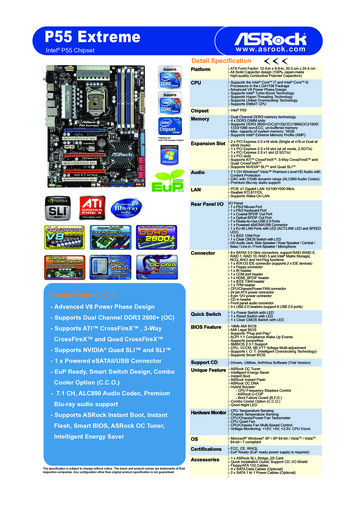
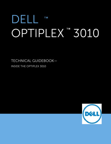
512Mb: x4, x8, x16 DDR SDRAMState DiagramState DiagramFigure 2:Simplified State DiagramPoweronPowerappliedPREPrechargeall banksSelfrefreshLMRREFSREFSXIdleREFAall werdownPrechargepowerdownACTCKE HIGHCKE LOWRowactiveBurststopREADWRITEBSTWRITEWRITE AREAD AREADWriteWRITE AREAD APREWrite AREADReadREAD APREPRERead APrechargePREALLPREAutomatic sequenceCommand sequenceACT ACTIVEBST BURST TERMINATECKEH Exit power-downCKEL Enter power-downEMR Extended mode registerLMR LOAD MODE REGISTERMR Mode registerNote:This diagram represents operations within a single bank only and does not capture concurrent operations in other banks.PDF: 09005aef80768abb/Source: 09005aef82a95a3aDDR x4x8x16 Core1.fm - 512Mb DDR: Rev. Q; Core DDR Rev. E 7/11 ENDownloaded from Arrow.com.PRE PRECHARGEPREALL PRECHARGE all banksREAD A READ with auto prechargeREFA AUTO REFRESHREFS Enter self refreshREFSX Exit self refreshWRITE A WRITE with auto precharge4Micron Technology, Inc., reserves the right to change products or specifications without notice. 2000 Micron Technology, Inc. All rights reserved.
512Mb: x4, x8, x16 DDR SDRAMFunctional DescriptionFunctional DescriptionThe DDR SDRAM uses a double data rate architecture to achieve high-speed operation.The double data rate architecture is essentially a 2n-prefetch architecture with an interface designed to transfer two data words per clock cycle at the I/O pins. A single read orwrite access for the DDR SDRAM effectively consists of a single 2n-bit-wide, one-clockcycle data transfer at the internal DRAM core and two corresponding n-bit-wide, onehalf-clock-cycle data transfers at the I/O pins.A bidirectional data strobe (DQS) is transmitted externally, along with data, for use indata capture at the receiver. DQS is a strobe transmitted by the DDR SDRAM duringREADs and by the memory controller during WRITEs. DQS is edge-aligned with data forREADs and center-aligned with data for WRITEs. The x16 offering has two data strobes,one for the lower byte and one for the upper byte.The DDR SDRAM operates from a differential clock (CK and CK#); the crossing of CKgoing HIGH and CK# going LOW will be referred to as the positive edge of CK.Commands (address and control signals) are registered at every positive edge of CK.Input data is registered on both edges of DQS, and output data is referenced to bothedges of DQS, as well as to both edges of CK.Read and write accesses to the DDR SDRAM are burst oriented; accesses start at aselected location and continue for a programmed number of locations in a programmedsequence. Accesses begin with the registration of an ACTIVE command, which may thenbe followed by a READ or WRITE command. The address bits registered coincident withthe ACTIVE command are used to select the bank and row to be accessed. The addressbits registered coincident with the READ or WRITE command are used to select the bankand the starting column location for the burst access.The DDR SDRAM provides for programmable READ or WRITE burst lengths of 2, 4, or 8locations. An auto precharge function may be enabled to provide a self-timed rowprecharge that is initiated at the end of the burst access.As with standard SDR SDRAMs, the pipelined, multibank architecture of DDR SDRAMsallows for concurrent operation, thereby providing high effective bandwidth by hidingrow precharge and activation time.An auto refresh mode is provided, along with a power-saving power-down mode. Allinputs are compatible with the JEDEC standard for SSTL 2. All full-drive option outputsare SSTL 2, Class II compatible.General Notes The functionality and the timing specifications discussed in this data sheet are for theDLL-enabled mode of operation. Throughout the data sheet, the various figures and text refer to DQs as “DQ.” The DQterm is to be interpreted as any and all DQ collectively, unless specifically statedotherwise. Additionally, the x16 is divided into two bytes, the lower byte and upperbyte. For the lower byte (DQ[7:0]) DM refers to LDM and DQS refers to LDQS. For theupper byte (DQ[15:8]) DM refers to UDM and DQS refers to UDQS. Complete functionality is described throughout the document and any page ordiagram may have been simplified to convey a topic and may not be inclusive of allrequirements. Any specific requirement takes precedence over a general statement.PDF: 09005aef80768abb/Source: 09005aef82a95a3aDDR x4x8x16 Core1.fm - 512Mb DDR: Rev. Q; Core DDR Rev. E 7/11 ENDownloaded from Arrow.com.5Micron Technology, Inc., reserves the right to change products or specifications without notice. 2000 Micron Technology, Inc. All rights reserved.
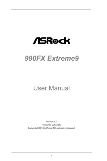
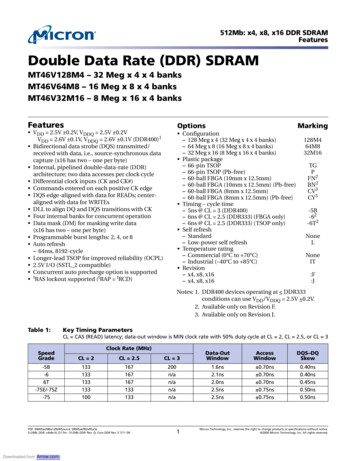
512Mb: x4, x8, x16 DDR SDRAMFunctional Block DiagramsFunctional Block DiagramsThe 512Mb DDR SDRAM is a high-speed CMOS, dynamic random-access memorycontaining 536,870,912 bits. It is internally configured as a 4-bank DRAM.Figure 3:128 Meg x 4 Functional Block OGICBANK3BANK2BANK1MODE REGISTERSREFRESH ECODER8192CKBANK0MEMORYARRAY(8,192 x 2,048 x 8)DLLDATA48READLATCHSENSE 0I/O GATINGDM MASK LOGIC2A0–A12,BA0, 8RCVRSDM4DATACK1COL01PDF: 09005aef80a1d9d4/Source: 09005aef82a95a3a512Mb DDR x4x8x16 D2.fm - 512Mb DDR: Rev. Q; Core DDR Rev. E 7/11 ENDownloaded from Arrow.com.6Micron Technology, Inc., reserves the right to change products or specifications without notice. 2000 Micron Technology, Inc. All rights reserved.
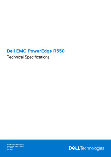
512Mb: x4, x8, x16 DDR SDRAMFunctional Block DiagramsFigure 4:64 Meg x 8 Functional Block RAS#BANK3BANK2BANK1REFRESH 13COUNTERMODE ER13138192CKBANK0MEMORYARRAY(8,192 x 1,024 x 16)DLLDATA816READLATCHSENSE ��A12,BA0, BA115ADDRESSREGISTERCOL0I/O GATINGDM MASK ATACK1COL01Figure 5:32 Meg x 16 Functional Block OGICBANK3BANK2BANK1REFRESHCOUNTER13MODE ECODER8192CKBANK0MEMORYARRAY(8,192 x 512 x 32)1632READLATCHSENSE COL0I/O GATINGDM MASK LOGIC2A0–A12,BA0, BA115ADDRESSREGISTER2322LDQS, 2WRITEFIFO&DRIVERSCKOutCKIn22216161616432RCVRSLDM, UDM16DATACK2COL01PDF: 09005aef80a1d9d4/Source: 09005aef82a95a3a512Mb DDR x4x8x16 D2.fm - 512Mb DDR: Rev. Q; Core DDR Rev. E 7/11 ENDownloaded from Arrow.com.7Micron Technology, Inc., reserves the right to change products or specifications without notice. 2000 Micron Technology, Inc. All rights reserved.
512Mb: x4, x8, x16 DDR SDRAMPin and Ball Assignments and DescriptionsPin and Ball Assignments and DescriptionsFigure 6:66-Pin TSOP Pin Assignment (Top View)x4x16x8VDDVDDVDDNFDQ0DQ0VDDQVDDQ QVDDQ DDQ VDDQNCNC S# CAS#RAS#RAS# RAS#CS#CS#CS#NCNCNCBA0BA0BA0BA1BA1BA1A10/AP A10/AP A10/APA0A0A0A1A1A1A2A2A2A3A3A3VDDVDDVDDPDF: 09005aef80a1d9d4/Source: 09005aef82a95a3a512Mb DDR x4x8x16 D2.fm - 512Mb DDR: Rev. Q; Core DDR Rev. E 7/11 ENDownloaded from ENCA12A11A9A8A7A6A5A4VSSMicron Technology, Inc., reserves the right to change products or specifications without notice. 2000 Micron Technology, Inc. All rights reserved.
512Mb: x4, x8, x16 DDR SDRAMPin and Ball Assignments and DescriptionsFigure 7:60-Ball FBGA Ball Assignment (Top View)x4 (Top View)1234NFVSSQVSSNC VDDQ DQ3NC VSSQNFNC VDDQ DQ2NC VSSQ DQSVSSVREFDMCKCK#A12 0A2VDDABCDEFGHJKLM89NF VDDQVSSQ NCVDDQ NCVSSQ NCVDDQ NCVDD DNUCAS#CS#BA0A10A1A3x8 (Top View)12VSSQ DQ7NC VDDQNC VSSQNC VDDQNC FGHJKLM89DQ0 VDDQVSSQ NCVDDQ NCVSSQ NCVDDQ NCVDD DNUCAS#CS#BA0A10A1A3x16 (Top 5VSSPDF: 09005aef80a1d9d4/Source: 09005aef82a95a3a512Mb DDR x4x8x16 D2.fm - 512Mb DDR: Rev. Q; Core DDR Rev. E 7/11 ENDownloaded from 1A3VDDQDQ1DQ3DQ5DQ7DNU9Micron Technology, Inc., reserves the right to change products or specifications without notice. 2000 Micron Technology, Inc. All rights reserved.
512Mb: x4, x8, x16 DDR SDRAMPin and Ball Assignments and DescriptionsTable 4:Pin and Ball ptionK7, L8, L7,M8, M2, L3,L2, K3, K2,J3, K8,J2, H229, 30, 31,32, 35, 36,37, 38, 39,40, 2841, 42A0, A1, A2,A3, A4, A5,A6, A7, A8,A9, A10,A11, A12InputJ8, J726, 27BA0, BA1InputG2, G345, 46CK, CK#InputH344CKEInputH824CS#InputF3F7, F34720,47DMLDM, UDMInputH7, G8,G7A8, B9, B7,C9, C7, D9,D7, E9, E1,D3, D1, C3,C1, B3, B1,A2A8, B7, C7,D7, D3, C3,B3, A2B7, D7, D3,B323, 22,212, 4, 5,7, 8, 10,11, 13, 54,56, 57, 59,60, 62, 63,652, 5, 8,11, 56, 59,62, 655, 11, 56,62RAS#, DQ[2:0]DQ[5:3]DQ6, DQ7DQ[2:0]DQ3InputI/OAddress inputs: Provide the row address for ACTIVE commands, and thecolumn address and auto precharge bit (A10) for READ/WRITEcommands, to select one location out of the memory array in therespective bank. A10 sampled during a PRECHARGE commanddetermines whether the PRECHARGE applies to one bank (A10 LOW,bank selected by BA0, BA1) or all banks (A10 HIGH). The address inputsalso provide the op-code during a LOAD MODE REGISTER command.Bank address inputs: BA0 and BA1 define to which bank an ACTIVE,READ, WRITE, or PRECHARGE command is being applied. BA0 and BA1also define which mode register (mode register or extended moderegister) is loaded during the LOAD MODE REGISTER (LMR) command.Clock: CK and CK# are differential clock inputs. All address and controlinput signals are sampled on the crossing of the positive edge of CK andnegative edge of CK#. Output data (DQ and DQS) is referenced to thecrossings of CK and CK#.Clock enable: CKE HIGH activates and CKE LOW deactivates the internalclock, input buffers, and output drivers. Taking CKE LOW providesPRECHARGE POWER-DOWN and SELF REFRESH operations (all banksidle), or ACTIVE POWER-DOWN (row ACTIVE in any bank). CKE issynchronous for POWER-DOWN entry and exit, and for SELF REFRESHentry. CKE is asynchronous for SELF REFRESH exit and for disabling theoutputs. CKE must be maintained HIGH throughout read and writeaccesses. Input buffers (excluding CK, CK#, and CKE) are disabled duringPOWER-DOWN. Input buffers (excluding CKE) are disabled during SELFREFRESH. CKE is an SSTL 2 input but will detect an LVCMOS LOW levelafter VDD is applied and until CKE is first brought HIGH, after which itbecomes a SSTL 2 input only.Chip select: CS# enables (registered LOW) and disables (registeredHIGH) the command decoder. All commands are masked when CS# isregistered HIGH. CS# provides for external bank selection on systems withmultiple banks. CS# is considered part of the command code.Input data mask: DM is an input mask signal for write data. Input datais masked when DM is sampled HIGH along with that input data during awrite access. DM is sampled on both edges of DQS. Although DM pins areinput-only, the DM loading is designed to match that of DQ and DQSpins. For the x16, LDM is DM for DQ[7:0] and UDM is DM for DQ[15:8]. Pin20 is a NC on x4 and x8.Command inputs: RAS#, CAS#, and WE# (along with CS#) define thecommand being entered.Data input/output: Data bus for x16.I/OData input/output: Data bus for x8.I/OData input/output: Data bus for x4.PDF: 09005aef80a1d9d4/Source: 09005aef82a95a3a512Mb DDR x4x8x16 D2.fm - 512Mb DDR: Rev. Q; Core DDR Rev. E 7/11 ENDownloaded from Arrow.com.10Micron Technology, Inc., reserves the right to change products or specifications without notice. 2000 Micron Technology, Inc. All rights reserved.
512Mb: x4, x8, x16 DDR SDRAMPin and Ball Assignments and DescriptionsTable 4:Pin and Ball Descriptions upplySupplySupplyNC–No connect for x16: These pins should be left unconnected.NC–No connect for x8: These pins should be left unconnected.NC–No connect for x4: These pins should be left unconnected.NF–No function for x4: These pins should be left unconnected.DNU–Do not use: Must float to minimize noise on VREF.F8, M7, A71, 18, 33B2, D2, C8, 3, 9, 15, 55,E8, A961F149A3, F2, M3 34, 48, 66A1, C2, E2,6, 12, 52,B8, D858, 64–14, 17, 25,43, 53B1, B9, C1,4, 7, 10,C9, D1, D9, 13, 14, 16,E1, E7, E9, 17, 20, 25,F743, 53, 54,57, 60, 63B1, B9, C1, 4, 7, 10, 13,C9, D1, D9, 14, 16, 17,E1, E7, E9, 20, 25, 43,F753, 54, 57,60, 63A2, A8, C3, 2, 8, 59, 65C7F919, 50Table 5:DescriptionData strobe: Output with read data, input with write data. DQS is edgealigned with read data, centered in write data. It is used to capture data.For the x16, LDQS is DQS for DQ[7:0] and UDQS is DQS for DQ[15:8]. Pin16 (E7) is NC on x4 and x8.Power supply: 2.5V 0.2V. (2.6V 0.1V for DDR400).DQ power supply: 2.5V 0.2V (2.6V 0.1V for DDR400). Isolated on thedie for improved noise immunity.SSTL 2 reference voltage.Ground.DQ ground: Isolated on the die for improved noise immunity.Reserved NC Pin and Ball DescriptionsNC pins not listed may also be reserved for other uses; this table defines NC pins of utAddress input A13 for 1Gb devices.PDF: 09005aef80a1d9d4/Source: 09005aef82a95a3a512Mb DDR x4x8x16 D2.fm - 512Mb DDR: Rev. Q; Core DDR Rev. E 7/11 ENDownloaded from Arrow.com.11Micron Technology, Inc., reserves the right to change products or specifications without notice. 2000 Micron Technology, Inc. All rights reserved.
512Mb: x4, x8, x16 DDR SDRAMPackage DimensionsPackage DimensionsFigure 8:66-Pin Plastic TSOP (400 mil)SEE DETAIL A22.22 0.080.710.65 TYP0.10 (2X)0.32 .075 TYP11.76 0.2010.16 0.08 0.030.15 –0.02PIN #1 IDGAGE PLANE0.100.25 0.10–0.050.100.80 TYP1.20 MAX0.50 0.10DETAIL ANotes:1. All dimensions are in millimeters.2. Package width and length do not include mold protrusion; allowable mold protrusion is0.25mm per side.3. Not all packages will have the half moon shaped notches as shown.PDF: 09005aef80a1d9d4/Source: 09005aef82a95a3a512Mb DDR x4x8x16 D2.fm - 512Mb DDR: Rev. Q; Core DDR Rev. E 7/11 ENDownloaded from Arrow.com.12Micron Technology, Inc., reserves the right to change products or specifications without notice. 2000 Micron Technology, Inc. All rights reserved.
512Mb: x4, x8, x16 DDR SDRAMPackage DimensionsFigure 9:60-Ball FBGA (10mm x 12.5mm)0.85 0.05SEATING PLANEC0.10 C6.4060X Ø .45SOLDER BALL DIAMETERREFERS TO POST REFLOWCONDITION. THE PRE-REFLOWDIAMETER IS Ø 0.40.0.80 (TYP)BALL A1BALL A1 I
A bidirectional data strobe (DQS) is transmit ted externally, along with data, for use in data capture at the receiver. DQS is a strobe transmitted by the DDR SDRAM during READs and by the memory controller duri ng WRITEs. DQS is edge-aligned with data for READs and center-aligned with data for WRITEs. The x16 offering has two data strobes,