Transcription
990FX Extreme9User ManualVersion 1.0Published July 2013Copyright 2013 ASRock INC. All rights reserved.1
Copyright Notice:No part of this manual may be reproduced, transcribed, transmitted, or translated inany language, in any form or by any means, except duplication of documentation bythe purchaser for backup purpose, without written consent of ASRock Inc.Products and corporate names appearing in this manual may or may not be registered trademarks or copyrights of their respective companies, and are used only foridentification or explanation and to the owners’ benefit, without intent to infringe.Disclaimer:Specifications and information contained in this manual are furnished for informational use only and subject to change without notice, and should not be constructedas a commitment by ASRock. ASRock assumes no responsibility for any errors oromissions that may appear in this manual.With respect to the contents of this manual, ASRock does not provide warranty ofany kind, either expressed or implied, including but not limited to the implied warranties or conditions of merchantability or fitness for a particular purpose.In no event shall ASRock, its directors, officers, employees, or agents be liable forany indirect, special, incidental, or consequential damages (including damages forloss of profits, loss of business, loss of data, interruption of business and the like),even if ASRock has been advised of the possibility of such damages arising fromany defect or error in the manual or product.This device complies with Part 15 of the FCC Rules. Operation is subject to the following two conditions:(1) this device may not cause harmful interference, and(2) this device must accept any interference received, including interference thatmay cause undesired operation.CALIFORNIA, USA ONLYThe Lithium battery adopted on this motherboard contains Perchlorate, a toxicsubstance controlled in Perchlorate Best Management Practices (BMP) regulationspassed by the California Legislature. When you discard the Lithium battery in California, USA, please follow the related regulations in advance.“Perchlorate Material-special handling may apply, Rock Website: http://www.asrock.com2
Contents1. Introduction. 51.11.21.31.41.5Package Contents.Specifications.Unique Features.Motherboard Layout .I/O Panel . .661014152. Installation. 17Pre-installation Precautions. 172.1 CPU Installation. 182.2 Installation of CPU Fan and Heatsink . . 182.3 Installation of Memory Modules (DIMM). 192.4 Expansion Slots (PCI and PCI Express Slots). 212.5 SLITM, 3-Way SLITM, and Quad SLITM Operation Guide . 232.6 CrossFireXTM, 3-Way CrossFireXTM and Quad CrossFireXTMOperation Guide. 292.7 Surround Display Information. 332.8 ASRock Smart Remote Installation Guide. 342.9 Jumpers Setup. 362.10 Onboard Headers and Connectors . . 372.11 Smart Switches. 442.12 Dr. Debug . . 452.13 Serial ATA3 (SATA3) Hard Disks Installation . 462.14 Hot Plug and Hot Swap Functions for SATA3 HDDs. 462.15 SATA3 HDD Hot Plug Feature and Operation Operation Guide. 472.16 Driver Installation Guide. 492.17 Installing Windows 8 / 8 64-bit / 7 / 7 64-bit / VistaTM / VistaTM64-bit / XP / XP 64-bit With RAID Functions. 492.17.1 Installing Windows XP / XP 64-bit With RAIDFunctions. 492.17.2 Installing Windows 8 / 8 64-bit / 7 / 7 64-bit / VistaTM /VistaTM 64-bit With RAID Functions. 502.18 Installing Windows 8 / 8 64-bit / 7 / 7 64-bit / VistaTM / VistaTM64-bit / XP / XP 64-bit Without RAID Functions. 512.18.1 Installing Windows XP / XP 64-bit Without RAIDFunctions. 512.18.2 Installing Windows 8 / 8 64-bit / 7 / 7 64-bit / VistaTM /VistaTM 64-bit Without RAID Functions. 522.19 Untied Overclocking Technology . 523
3. UEFI SETUP UTILITY. 533.1Introduction. 533.23.33.43.53.63.73.83.93.1.1 UEFI Menu Bar. 533.1.2 Navigation Keys. 54Main Screen. 54OC Tweaker Screen. 55Advanced Screen. 593.4.1 CPU Configuration. 603.4.2 North Bridge Configuration. 613.4.3 South Bridge Configuration. 623.4.4 Storage Configuration. 633.4.5 Super IO Configuration. 653.4.6 ACPI Configuration. 663.4.7 USB Configuration. 68Tool . 69Hardware Health Event Monitoring Screen. 72Boot Screen. 73Security Screen. 75Exit Screen. 764. Software Support. 774.14.2Install Operating System.Support CD Information.4.2.1 Running Support CD.4.2.2 Drivers Menu.4.2.3 Utilities Menu.4.2.4 Contact Information.4777777777777
1. IntroductionThank you for purchasing ASRock 990FX Extreme9 motherboard, a reliable motherboard produced under ASRock’s consistently stringent quality control. It deliversexcellent performance with robust design conforming to ASRock’s commitment toquality and endurance.In this manual, chapter 1 and 2 contain introduction of the motherboard and stepby-step guide to the hardware installation. Chapter 3 and 4 contain the configurationguide to BIOS setup and information of the Support CD.Because the motherboard specifications and the BIOS software mightbe updated, the content of this manual will be subject to change withoutnotice. In case any modifications of this manual occur, the updated version will be available on ASRock website without further notice. You mayfind the latest VGA cards and CPU support lists on ASRock website aswell. ASRock website http://www.asrock.comIf you require technical support related to this motherboard, please visitour website for specific information about the model you are using.www.asrock.com/support/index.asp1.1 Package ContentsASRock 990FX Extreme9 Motherboard (ATX Form Factor)ASRock 990FX Extreme9 Quick Installation GuideASRock 990FX Extreme9 Support CD1 x ASRock SLI Bridge 2S Card1 x ASRock 3-Way SLI-2S1S Bridge Card6 x Serial ATA (SATA) Data Cables (Optional)2 x Serial ATA (SATA) HDD Power Cables (Optional)1 x I/O Panel Shield1 x Front USB 3.0 Panel with 2.5” HDD/SSD Rack4 x HDD Screws6 x Chassis Screws1 x Rear USB 3.0 BracketASRock Reminds You.To get better performance in Windows 8 / 8 64-bit / 7 / 7 64-bit / VistaTM/ VistaTM 64-bit, it is recommended to set the BIOS option in StorageConfiguration to AHCI mode.5
1.2 SpecificationsPlatformCPUChipsetMemoryExpansion SlotAudio- ATX Form Factor- Premium Gold Capacitor design (100% Japan-madehigh-quality Conductive Polymer Capacitors)- Multiple Filter Cap (MFC) (Filter different noise by 3 differentcapacitors: DIP solid cap, POSCAP and MLCC)- Support for Socket AM3 processors- Support for Socket AM3 processors: AMD PhenomTM II X6 /X4 / X3 / X2 (except 920 / 940) / Athlon II X4 / X3 / X2 /Sempron processors- Supports 8-Core CPU- Supports UCC feature (Unlock CPU Core) (see CAUTION 1)- Digi Power Design- Advanced 12 2 Power Phase Design- Dual-Stack MOSFET (DSM)- Supports CPU up to 140W- Supports AMD’s Cool ‘n’ QuietTM Technology- FSB 2600 MHz (5.2 GT/s)- Supports Untied Overclocking Technology- Supports Hyper-Transport 3.0 (HT 3.0) Technology- Northbridge: AMD 990FX- Southbridge: AMD SB950- Dual Channel DDR3 Memory Technology- 4 x DDR3 DIMM slots- Supports DDR3 2450(OC)/2100(OC)/1600/1333/1066non-ECC, un-buffered memory (see CAUTION 2)- Max. capacity of system memory: 64GB (see CAUTION 3)- Supports Intel Extreme Memory Profile (XMP) 1.3 / 1.2- Supports AMD Memory Profile (AMP)- 4 x PCI Express 2.0 x16 slots (PCIE1 @ x16 mode; PCIE3@ x4 mode; PCIE4/PCIE5: single at x16 (PCIE4) / x8 (PCIE5)or dual at x8/x8 mode)- 1 x PCI Express 2.0 x1 slot- 1 x PCI slot- Supports AMD Quad CrossFireXTM, 3-Way CrossFireXTMand CrossFireXTM- Supports NVIDIA Quad SLITM, 3-Way SLITM and SLITM- 7.1 CH HD Audio with Content Protection(Realtek ALC898 Audio Codec)- Premium Blu-ray audio support6
LANRear Panel I/OSATA3USB 3.0Connector- PCIE x1 Gigabit LAN 10/100/1000 Mb/s- Intel 82583V- Supports Wake-On-LAN- Supports PXEI/O Panel- 1 x PS/2 Mouse Port- 1 x PS/2 Keyboard Port- 1 x Coaxial SPDIF Out Port- 1 x Optical SPDIF Out Port- 4 x Ready-to-Use USB 2.0 Ports- 4 x Ready-to-Use USB 3.0 Ports- 2 x eSATA3 Connectors- 1 x RJ-45 LAN Port with LED (ACT/LINK LED and SPEEDLED)- 1 x IEEE 1394 Port- 1 x Clear CMOS Switch with LED- HD Audio Jack: Side Speaker/Rear Speaker/Central/Bass/Line in/Front Speaker/Microphone- 6 x SATA3 6.0 Gb/s connectors by AMD SB950, supportRAID (RAID 0, RAID 1, RAID 0 1, JBOD and RAID 5),NCQ, AHCI and “Hot Plug” functions- 2 x SATA3 6.0 Gb/s connectors by ASMedia ASM1061,support NCQ, AHCI and “Hot Plug” functions- 4 x Rear USB 3.0 ports by Etron EJ188H, supportUSB 1.1/2.0/3.0 up to 5Gb/s- 2 x Front USB 3.0 headers (support 4 USB 3.0 ports) byEtron EJ188H, support USB 1.1/2.0/3.0 up to 5Gb/s- 8 x SATA3 6.0Gb/s connectors- 1 x IR header- 1 x CIR header- 1 x COM port header- 1 x IEEE 1394 header- 1 x Power LED header- 2 x CPU Fan connectors (1 x 4-pin, 1 x 3-pin)- 3 x Chassis Fan connectors (1 x 4-pin, 2 x 3-pin)- 1 x Power Fan connector (3-pin)- 24 pin ATX power connector- 8 pin 12V power connector (Hi-Density Power Connector)- Front panel audio connector- 2 x USB 2.0 headers (support 4 USB 2.0 ports)7
BIOS FeatureSupport CDHardwareMonitorOSCertifications- 2 x USB 3.0 headers (support 4 USB 3.0 ports)- 1 x Dr. Debug (7-Segment Debug LED)- 1 x Power Switch with LED- 1 x Reset Switch with LED- 32Mb AMI UEFI Legal BIOS with GUI support- Supports “Plug and Play”- ACPI 1.1 Compliance Wake Up Events- Supports jumperfree- SMBIOS 2.3.1 Support- CPU, VCCM, NB, SB Voltage Multi-adjustment- Drivers, Utilities, AntiVirus Software (Trial Version),CyberLink MediaEspresso 6.5 Trial, Google ChromeBrowser and Toolbar- CPU Temperature Sensing- Chassis Temperature Sensing- CPU/Chassis/Power Fan Tachometer- CPU/Chassis Quiet Fan- CPU/Chassis/Power Fan Multi-Speed Control- Voltage Monitoring: 12V, 5V, 3.3V, Vcore- Microsoft Windows 8 / 8 64-bit / 7 / 7 64-bit / VistaTM /VistaTM 64-bit / XP / XP 64-bit compliant- FCC, CE, WHQL- ErP/EuP Ready (ErP/EuP ready power supply is required)* For detailed product information, please visit our website: http://www.asrock.comWARNINGPlease realize that there is a certain risk involved with overclocking,including adjusting the setting in the BIOS, applying Untied OverclockingTechnology, or using third-party overclocking tools. Overclocking mayaffect your system’s stability, or even cause damage to the componentsand devices of your system. It should be done at your own risk andexpense. We are not responsible for possible damage caused byoverclocking.8
CAUTION!1. ASRock UCC (Unlock CPU Core) feature simplifies AMD CPUactivation. As long as a simple switch of the UEFI option “ASRock UCC”, you can unlock the extra CPU core to enjoy aninstant performance boost. When UCC feature is enabled, thedual-core or triple-core CPU will boost to the quad-core CPU,and some CPU, including quad-core CPU, can also increase L3cache size up to 6MB, which means you can enjoy the upgradeCPU performance with a better price. Please be noted that UCCfeature is supported with AM3/AM3 CPU only, and in addition,not every AM3/AM3 CPU can support this function becausesome CPU’s hidden core may be malfunctioned.2. Whether 2450/2100MHz memory speed is supported dependson the AM3/AM3 CPU you adopt. If you want to adopt DDR32450/2100 memory module on this motherboard, please referto the memory support list on our website for the compatiblememory modules.ASRock website: http://www.asrock.com3. Due to the operating system limitation, the actual memory sizemay be less than 4GB for the reservation for system usage under Windows 8 / 7 / VistaTM. For Windows 64-bit OS with 64bit CPU, there is no such limitation. You can use ASRock XFastRAM to utilize the memory that Windows cannot use.9
1.3 Unique FeaturesASRock Extreme Tuning Utility (AXTU)ASRock Extreme Tuning Utility (AXTU) is an all-in-one tool tone-tune different system functions in a user-friendly interface,which includes Hardware Monitor, Fan Control, Overclocking,OC DNA, IES and XFast RAM. In Hardware Monitor, it showsthe major readings of your system. In Fan Control, it shows thefan speed and temperature for you to adjust. In Overclocking,you are allowed to overclock CPU frequency for optimal systemperformance. In OC DNA, you can save your OC settings asa profile and share it with your friends. Your friends then canload the OC profile to their own system to get the same OC settings. In IES (Intelligent Energy Saver), the voltage regulatorcan reduce the number of output phases to improve efficiencywhen the CPU cores are idle without sacrificing computing performance. In XFast RAM, it fully utilizes the memory space thatcannot be used under Windows OS 32-bit CPU.ASRock Instant BootASRock Instant Boot allows you to turn on your PC in just a fewseconds, provides a much more efficient way to save energy,time, money, and improves system running speed for your system. It leverages the S3 and S4 ACPI features which normallyenable the Sleep/Standby and Hibernation modes in Windows to shorten boot up time. By calling S3 and S4 at specific timingduring the shutdown and startup process, Instant Boot allowsyou to enter your Windows desktop in a few seconds.ASRock Instant FlashASRock Instant Flash is a BIOS flash utility embedded in FlashROM. This convenient BIOS update tool allows you to updatesystem BIOS without entering operating systems first like MSDOS or Windows . With this utility, you can press the F6 keyduring the POST or the F2 key to enter into the BIOS setupmenu to access ASRock Instant Flash. Just launch this tool andsave the new BIOS file to your USB flash drive, floppy disk orhard drive, then you can update your BIOS only in a few clickswithout preparing an additional floppy diskette or other complicated flash utility. Please be noted that the USB flash drive orhard drive must use FAT32/16/12 file system.10
ASRock APP ChargerIf you desire a faster, less restricted way of charging yourApple devices, such as iPhone/iPad/iPod Touch, ASRock hasprepared a wonderful solution for you - ASRock APP Charger.Simply install the APP Charger driver, it makes your iPhonecharge much quickly from your computer and up to 40% fasterthan before. ASRock APP Charger allows you to quickly chargemany Apple devices simultaneously and even supports continuous charging when your PC enters into Standby mode (S1),Suspend to RAM (S3), hibernation mode (S4) or power off (S5).With APP Charger driver installed, you can easily enjoy the marvelous charging experience.ASRock XFast USBASRock XFast USB can boost USB storage device performance. The performance may depend on the properties of thedevice.ASRock XFast LANASRock XFast LAN provides a faster internet access, which includes the benefits listed below. LAN Application Prioritization:You can configure your application’s priority ideally and/or addnew programs. Lower Latency in Game: After setting onlinegame’s priority higher, it can lower the latency in games. TrafficShaping: You can watch Youtube HD videos and download simultaneously. Real-Time Analysis of Your Data: With the statuswindow, you can easily recognize which data streams you aretransferring currently.ASRock XFast RAMASRock XFast RAM is a new function that is included into ASRock Extreme Tuning Utility (AXTU). It fully utilizes the memoryspace that cannot be used under Windows OS 32-bit CPU.ASRock XFast RAM shortens the loading time of previouslyvisited websites, making web surfing faster than ever. And italso boosts the speed of Adobe Photoshop 5 times faster. Another advantage of ASRock XFast RAM is that it reduces thefrequency of accessing your SSDs or HDDs in order to extendtheir lifespan.11
ASRock Crashless BIOSASRock Crashless BIOS allows users to update their BIOSwithout fear of failing. If power loss occurs during the BIOS update process, ASRock Crashless BIOS will automatically finishthe BIOS update procedure after regaining power. Please notethat BIOS files need to be placed in the root directory of yourUSB disk. Only USB2.0 ports support this feature.ASRock OMG (Online Management Guard)Administrators are able to establish an internet curfew or restrictinternet access at specified times via OMG. You may schedulethe starting and ending hours of internet access granted to otherusers. In order to prevent users from bypassing OMG, guestaccounts without permission to modify the system time are required.ASRock Internet FlashASRock Internet Flash searches for available UEFI firmwareupdates from our servers. In other words, the system can autodetect the latest UEFI from our servers and flash them withoutentering Windows OS.ASRock UEFI System BrowserASRock UEFI system browser is a useful tool included ingraphical UEFI. It can detect the devices and configurationsthat users are currently using in their PC. With the UEFI systembrowser, you can easily examine the current system configuration in UEFI setup.ASRock Dehumidifier FunctionUsers may prevent motherboard damages due to dampness byenabling “Dehumidifier Function”. When enabling DehumidifierFunction, the computer will power on automatically to dehumidify the system after entering S4/S5 state.ASRock Easy RAID InstallerASRock Easy RAID Installer can help you to copy the RAIDdriver from a support CD to your USB storage device. Aftercopying the RAID driver to your USB storage device, pleasechange “SATA Mode” to “RAID”, then you can start installing theOS in RAID mode.12
ASRock Fast BootWith ASRock’s exclusive Fast Boot technology, it takes lessthan 1.5 seconds to logon to Windows 8 from a cold boot. Nomore waiting! The speedy boot will completely change your userexperience and behavior.ASRock X-BoostASRock’s X-Boost Technology is a smart auto-overclockingfunction and is brilliantly designed to unlock the hidden power ofyour CPUs. Simply press “X” when turning on the PC, X-Boostwill automatically overclock the relative components to get up to15.77% performance boost! With the smart X-Boost, overclocking CPU can become a near one-button process.* The functionality of “Unlock CPU Cores” feature might vary bydifferent processors.ASRock Restart to UEFIWindows 8 brings the ultimate boot up experience. The lightning boot up speed makes it hard to access the UEFI setup. ASRock Restart to UEFI technology is designed for those requiringfrequent UEFI access. It allows users to easily enter the UEFIautomatically when turning on the PC next time. Just simplyenable this function; the PC will be assured to access the UEFIdirectly in the very beginning.Turbo 50 / Turbo 60 OverclockingSimply click the Turbo 50 / Turbo 60 button in UEFI, the systemperformance will boost up to 50% or 60% increase by automatically overclocking CPU, Memory frequency and all related voltage settings.ASRock Good Night LEDASRock Good Night LED technology can offer you a better environment by extinguishing the unessential LED. By enablingGood Night LED in BIOS, the Power / HDD / LAN LED will beswitched off when system is on. Not only this, Good night LEDwill automatically switch off Power and Keyboard LED when thesystem enters into Standby / Hibernation mode as well.13
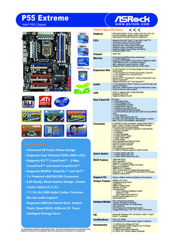
1.4 Motherboard Layout3 421PS2MousePS2KeyboardCPU FAN15 6CPU FAN2789PWR FAN1CHA FAN2ATX12V1ClrCMOSFSB800DDR3 B2 (64 bit, 240-pin module)FSB800USB 3.0T: USB2 Top:RJ-45B: USB3DDR3 A2 (64 bit, 240-pin module)USB 2.0T: USB2B: USB3DDR3 B1 (64 bit, 240-pin module)USB 2.0T: USB0B: USB11011Center:FRONTTop:LINE INBottom:MIC INUSB3 6 7Center:REAR SPKBottom:CTR BASSTop:SIDE 0PCIE2990FX Extreme937PCI13635RoHS32MbBIOSCHA FAN311341PLED1USB4 5PANEL 13332USB6 7PLED ER1PCIE5FRONT 1394HD AUDIO1116SATA3 3 4PCIE43815SATA3 5 6SuperI/OSATA3 A1 A2AMDSB950ChipsetPCIE3SATA3 1 23981213411234567USB3 4 5IEEE 1394eSATASOCKET AM3beSATADDR3 A1 (64 bit, 240-pin module)OpticalSPDIFCoaxialSPDIFUSB 3.0T: USB0B: USB11111CLRCMOS11HDLEDCIR1RESET31 30 29 28CHA FAN1RSTBTN27 26 25 24 23 22ATX 12V Power Connector (ATX12V1)21CPU Heatsink Retention Module22AM3 CPU Socket23CPU Fan Connector (CPU FAN1)24CPU Fan Connector (CPU FAN2)25Chassis Fan Connector (CHA FAN2)262 x 240-pin DDR3 DIMM Slots27(Dual Channel A: DDR3 A1, DDR3 B1)282 x 240-pin DDR3 DIMM Slots29(Dual Channel B: DDR3 A2, DDR3 B2)30Power Fan Connector (PWR FAN1)31ATX Power Connector (ATXPWR1)32USB 3.0 Header (USB3 6 7)33USB 3.0 Header (USB3 4 5)Northbridge Controller34Southbridge Controller35SATA3 Connector (SATA3 A1 A2)36SATA3 Connector (SATA3 5 6)37SATA3 Connector (SATA3 3 4)38SATA3 Connector (SATA3 1 2)39Chassis Speaker Header (SPEAKER1)40Chassis Fan Connector (CHA FAN1)4114Dr.DebugPWRBTN1121 20Power Switch (PWRBTN)Reset Switch (RSTBTN)Dr. Debug (LED)Chassis Fan Connector (CHA FAN3)USB 2.0 Header (USB6 7)USB 2.0 Header (USB4 5)Consumer Infrared Module Header (CIR1)System Panel Header (PANEL1)Clear CMOS Jumper (CLRCMOS1)Power LED Header (PLED1)Serial Port Connector (COM1)Infrared Module Header (IR1)Front Panel IEEE 1394 Header(FRONT 1394)Front Panel Audio Header (HD AUDIO1)PCI Express 2.0 x16 Slot (PCIE5)SPI Flash Memory (32Mb)PCI Slot (PCI1)PCI Express 2.0 x16 Slot (PCIE4)PCI Express 2.0 x16 Slot (PCIE3)PCI Express 2.0 x1 Slot (PCIE2)PCI Express 2.0 x16 Slot (PCIE1)
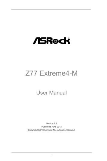
1.5 I/O Panel1191234*56789** 10321816 15174514 13PS/2 Mouse Port (Green)Coaxial SPDIF Out PortUSB 2.0 Ports (USB01)USB 2.0 Port (USB23)LAN RJ-45 PortSide Speaker (Gray)Rear Speaker (Black)Central / Bass (Orange)Line In (Light Blue)Front Speaker (Lime)111213*** 14*** 15161718196971081112Microphone (Pink)USB 3.0 Ports (USB3 2 3)IEEE 1394 Port (IEEE 1394)eSATA3 Connector (ESATA1)eSATA3 Connector (ESATA2)USB 3.0 Ports (USB3 0 1)Optical SPDIF Out PortClear CMOS Switch (CLRCBTN)PS/2 Keyboard Port (Purple)* There are two LED next to the LAN port. Please refer to the table below for the LAN port LEDindications.LAN Port LED IndicationsActivity/Link LEDStatusDescriptionStatusOffNo LinkBlinking Data ActivityOnLinkOffOrangeGreenSPEED LEDDescriptionACT/LINK SPEEDLEDLED10Mbps connection100Mbps connection1Gbps connectionLAN Port** If you use 2-channel speaker, please connect the speaker’s plug into “Front Speaker Jack”.See the table below for connection details in accordance with the type of speaker you use.TABLE for Audio Output ConnectionAudio Output Channels Front Speaker Rear Speaker(No. 10)(No. 7)2V-4VV6VV8VV15Central / Bass(No. 8)--VVSide Speaker(No. 6)---V
To enable Multi-Streaming function, you need to connect a front panel audio cable to the frontpanel audio header. After restarting your computer, you will find “Mixer” tool on your system.Please select “Mixer ToolBox”, click “Enable playback multi-streaming”, and click “ok”.Choose “2CH”, “4CH”, “6CH”, or “8CH” and then you are allowed to select “Realtek HDA Primary output” to use Rear Speaker, Central/Bass, and Front Speaker, or select “Realtek HDAAudio 2nd output” to use front panel audio.*** eSATA3 connector supports SATA Gen3 in cable 1M.16
2. InstallationThis is an ATX form factor motherboard. Before you install the motherboard, studythe configuration of your chassis to ensure that the motherboard fits into it.Pre-installation PrecautionsTake note of the following precautions before you install motherboardcomponents or change any motherboard settings.Before you install or remove any component, ensure that thepower is switched off or the power cord is detached from thepower supply. Failure to do so may cause severe damage to themotherboard, peripherals, and/or components.1.2.3.4.5.Unplug the power cord from the wall socket before touching anycomponent.To avoid damaging the motherboard components due to static electricity, NEVER place your motherboard directly on the carpet or thelike. Also remember to use a grounded wrist strap or touch a safetygrounded object before you handle components.Hold components by the edges and do not touch the ICs.Whenever you uninstall any component, place it on a grounded antistatic pad or in the bag that comes with the component.When placing screws into the screw holes to secure the motherboard to the chassis, please do not over-tighten the screws! Doingso may damage the motherboard.17
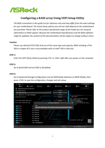
2.1 CPU InstallationoStep 1.Unlock the socket by lifting the lever up to a 90 angle.Step 2.Position the CPU directly above the socket such that the CPU corner withthe golden triangle matches the socket corner with a small triangle.Carefully insert the CPU into the socket until it fits in place.Step 3.The CPU fits only in one correct orientation. DO NOT force the CPUinto the socket to avoid bending of the pins.Step 4.When the CPU is in place, press it firmly on the socket while you pushdown the socket lever to secure the CPU. The lever clicks on the side tabto indicate that it is locked.Lever 90 UpCPU Golden TriangleSocker CornerSmall TriangleSTEP 1:Lift Up The Socket LeverSTEP 2 / STEP 3:STEP 4:Match The CPU Golden Triangle Push Down And LockTo The Socket Corner SmallThe Socket LeverTriangle2.2 Installation of CPU Fan and HeatsinkAfter you install the CPU into this motherboard, it is necessary to install alarger heatsink and cooling fan to dissipate heat. You also need to spraythermal grease between the CPU and the heatsink to improve heat dissipation. Make sure that the CPU and the heatsink are securely fastenedand in good contact with each other. Then connect the CPU fan to theCPU FAN connector (CPU FAN1, see Page 14, No. 4 or CPU FAN2,see Page 14, No. 5). For proper installation, please kindly refer to theinstruction manuals of the CPU fan and the heatsink.18
2.3 Installation of Memory Modules (DIMM)This motherboard provides four 240-pin DDR3 (Double Data Rate 3) DIMM slots,and supports Dual Channel Memory Technology. For dual channel configuration,you always need to install identical (the same brand, speed, size and chip-type)DDR3 DIMM pair in the slots. In other words, you have to install identical DDR3DIMM pair in Dual Channel (DDR3 A1 and DDR3 B1; see p.14 No.7) or identicalDDR3 DIMM pair in Dual Channel (DDR3 A2 and DDR3 B2; see p.14 No.8), sothat Dual Channel Memory Technology can be activated. This motherboard alsoallows you to install four DDR3 DIMMs for dual channel configuration, and pleaseinstall identical DDR3 DIMMs in all four slots. You may refer to the Dual ChannelMemory Configuration Table below.Dual Channel Memory ConfigurationsDDR3 A1(Black Slot)PopulatedPopulated(1)(2)(3)**DDR3 A2(Black Slot)PopulatedPopulatedDDR3 B1(Black Slot)PopulatedPopulatedDDR3 B2(Black Slot)PopulatedPopulatedFor the configuration (3), please install identical DDR3 DIMMs in all fourslots.1.2.3.4.5.6.Please install the memory module into DDR3 A2 and DDR3 B2slots for the first priority.If you want to install two memory modules, for optimal compatibilityand reliability, it is recommended to install them either in the setof DDR3 A1 and DDR3 B1 slots, or in the set of
- Supports Intel Extreme Memory Profile (XMP) 1.3 / 1.2 - Supports AMD Memory Profile (AMP) Expansion Slot - 4 x PCI Express 2.0 x16 slots (PCIE1 @ x16 mode; PCIE3 @ x4 mode; PCIE4/PCIE5: single at x16 (PCIE4) / x8 (PCIE5) or dual at x8/x8 mode) - 1 x PCI Express 2.0 x1 slot