Transcription
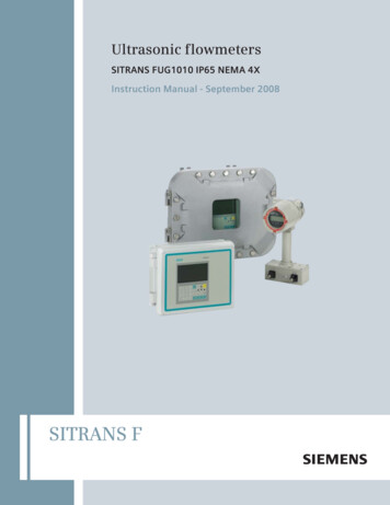
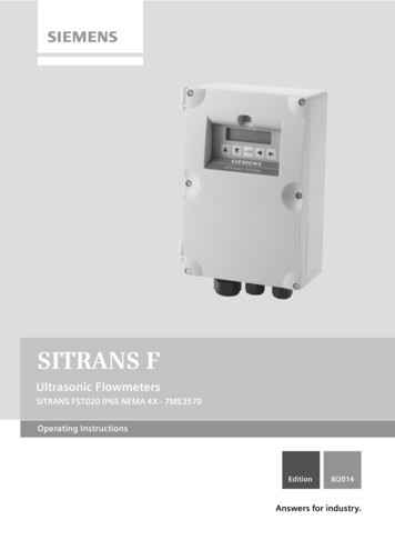
SITRANS FUltrasonic FlowmetersSITRANS FST020 IP65 NEMA 4X - 7ME3570Operating InstructionsEdition8/2014Answers for industry.
SITRANS FUltrasonic FlowmetersFST020 IP65 NEMA 4XIntroduction1Safety ommissioning6Functions7Alarm, error and systemmessages8Maintenance and Service9Operating Technical data11AppendixAAppendixB
Legal informationWarning notice systemThis manual contains notices you have to observe in order to ensure your personal safety, as well as to preventdamage to property. The notices referring to your personal safety are highlighted in the manual by a safety alertsymbol, notices referring only to property damage have no safety alert symbol. These notices shown below aregraded according to the degree of danger.DANGERindicates that death or severe personal injury will result if proper precautions are not taken.WARNINGindicates that death or severe personal injury may result if proper precautions are not taken.CAUTIONindicates that minor personal injury can result if proper precautions are not taken.NOTICEindicates that property damage can result if proper precautions are not taken.If more than one degree of danger is present, the warning notice representing the highest degree of danger willbe used. A notice warning of injury to persons with a safety alert symbol may also include a warning relating toproperty damage.Qualified PersonnelThe product/system described in this documentation may be operated only by personnel qualified for the specifictask in accordance with the relevant documentation, in particular its warning notices and safety instructions.Qualified personnel are those who, based on their training and experience, are capable of identifying risks andavoiding potential hazards when working with these products/systems.Proper use of Siemens productsNote the following:WARNINGSiemens products may only be used for the applications described in the catalog and in the relevant technicaldocumentation. If products and components from other manufacturers are used, these must be recommendedor approved by Siemens. Proper transport, storage, installation, assembly, commissioning, operation andmaintenance are required to ensure that the products operate safely and without any problems. The permissibleambient conditions must be complied with. The information in the relevant documentation must be observed.TrademarksAll names identified by are registered trademarks of Siemens AG. The remaining trademarks in this publicationmay be trademarks whose use by third parties for their own purposes could violate the rights of the owner.Disclaimer of LiabilityWe have reviewed the contents of this publication to ensure consistency with the hardware and softwaredescribed. Since variance cannot be precluded entirely, we cannot guarantee full consistency. However, theinformation in this publication is reviewed regularly and any necessary corrections are included in subsequenteditions.Siemens AGIndustry SectorPostfach 48 4890026 NÜRNBERGGERMANYOrder number: A5E03086487 07/2014 Subject to changeCopyright Siemens AG 2014.All rights reserved
Table of contents123456Introduction . 71.1Preface . 71.2Items supplied . 71.3History-Rev AJ . 81.4Further Information . 9Safety notes . 112.1General safety instructions .112.2Warning Symbols .122.3Laws and directives .132.4Lithium batteries .14Description . 153.1FST020 features .153.2NEMA 4X Transmitters .15Installing/Mounting . 174.1Determining a location .174.2Use according to specifications .174.3Application Guidelines .184.4Mounting the Transmitter .19Connecting . 235.15.1.15.1.2Transmitter Wiring .23Connecting Power .23ModBus/BACnet Setup .305.2Navigating the Menu .325.3Programming the Transmitter .335.45.4.15.4.25.4.35.4.45.4.5Installing the Sensor .37Preliminary Installation Procedures .37Sensor Identification and Selection.41Reflect Mount using Spacer Bar .45Direct Mount .491012T Mounting Tracks .545.55.5.1Sensor Wiring.63Wiring the Sensors .63Commissioning . 656.1Commissioning.65FST020 IP65 NEMA 4XOperating Instructions, 08/2014, A5E03086487-AJ3
Table of contents789106.2Empty Pipe Set . 666.3Installation Menus . 69Functions . 737.1Selecting Flow Units . 737.2Zero Flow Adjust Menu . 777.3Span Data . 817.4Logger Control . 837.5Operation Adjust Menu Settings . 857.6Analog Out Setup . 887.7Setting Relays . 897.8Pulse Out Setup . 917.9Memory Control . 967.10Analog Output Trim . 97Alarm, error and system messages .1018.1Alarm Codes . 1018.2Setting Alarm Levels . 102Maintenance and Service .1079.1Maintenance . 1079.2Technical support . 1079.3Return procedures . 108Troubleshooting .11110.1Troubleshooting . 11110.2Force Transmit . 11310.3System Reset . 11510.4Site Setup Data . 12011Technical data .125AAppendix .127A.1Certificates . 127A.2Ordering . 127A.3I/O Connections and Wiring . 127A.4Flowrate Calibration . 131A.5A.5.1A.5.2A.5.3A.5.4BACnet/ModBus Communications . 134Introduction. 134BACnet . 134BACnet Protocol Implementation Conformance Statement . 138ModBus . 140FST020 IP65 NEMA 4X4Operating Instructions, 08/2014, A5E03086487-AJ
Table of contentsBAppendix. 145B.1Installation/Outline Drawings .145Glossary . 147Index. 153TablesTable 4- 1CQO:1012NMB-1 Mounting Kit. 21Table 5- 15-Key Touch Keypad and PC Keyboard Function Chart . 32Table 5- 2Pipe Configuration Option List Definitions . 37Table 5- 3Universal Sensor Selection Chart . 42Table 5- 4High Precision Sensor Selection Chart . 43Table 7- 1Totalizer Modes. 74Table 7- 2Totalizer Controls . 76Table 7- 3Logger Control Menu Option List . 83Table 7- 4Operation Adjust Menu . 86Table 7- 5Analog Outputs . 88Table 7- 6Analog Out Setup Data Categories. 88Table 7- 7Relay 1 Option List . 90Table 7- 8Pulse Output Values for Gallons (US) . 96Table 7- 9Memory Control Menu . 96Table 7- 10Analog Out Trim Menu Structure . 97Table 10- 1Troubleshooting Tips . 111Table 10- 2Site Setup Menu Items . 120Table A- 1Part Numbers and Connection Diagrams . 127Table A- 2J8 Connector . 128Table A- 3J9 Connector (DB9) . 128Table A- 4Input/Output Wiring (TB1) . 129FiguresFigure 3-1Typical Transmitter Label . 16Figure 3-2NEMA 4X Transmitter . 16Figure 4-1Wall Mounting . 19Figure 4-2Pipe Mounting . 20Figure 5-1Input Power Wiring . 24FST020 IP65 NEMA 4XOperating Instructions, 08/2014, A5E03086487-AJ5
Table of contentsFigure 5-2Display Screen . 27Figure 5-3RS-232 Serial Port Menu Screen . 28Figure 5-4RS-232-Interface Cable Wiring . 29Figure 5-5RS-485 Wiring Diagram . 31Figure 5-65-Key Touch Keypad . 33Figure 5-7Reflect Mount (Pipe shown from above in 12 o'clock position) . 38Figure 5-8Direct Mount (Pipe shown from above in 12 o'clock position) . 38Figure 5-9Sensor Alignment . 40Figure 5-10Pipe Surface Preparation . 40Figure 5-11Sample Universal Sensor Label . 41Figure 5-12Sample Hi Precision Sensor Label . 42Figure 5-13Reflect Mount with Mounting Frames and Spacer Bar . 45Figure 5-14Reflect Mount, Spacer Bar-Side View . 46Figure 5-15Preparing the Pipe . 47Figure 5-16Sensor . 48Figure 5-17Sensor Installation . 48Figure 5-18Mylar Spacing Guide . 49Figure 5-19Wrap Strap Under Pipe and Attach to Adjusting Screw . 50Figure 5-20Aligning the Sensor to the Pipe . 51Figure 5-21Wrapping the Mylar Spacing Guide around the pipe (End View) . 52Figure 5-22Finding the Halfway Distance. 52Figure 5-23Aligning the Sensors for Direct Mode operation (End View) . 53Figure 5-24Reflect Mount with Model 1012TN Mounting Track (Side View) . 55Figure 5-25Direct Mount 180 opposed with Mounting Tracks . 57Figure 5-26Wrapping the Mylar Spacing Guide around the pipe (End View) . 59Figure 5-27Finding the Halfway Distance. 59Figure 5-28Track Rail Alignment . 60Figure 5-29REF and Number Index Pin Locations . 61Figure 5-30Connecting Sensor Cables to Transmitter . 63Figure 6-1Measuring Flow . 66Figure 7-1FST020 Output Wiring Terminals . 92Figure A-1Terminal TB1 including J8 Connector, DB9 Connector (J9), Power Connector (J12) andMenu Lockout Switch (S1) . 128Figure A-2Typical TB1 Wiring . 130Figure A-3Typical FST020 BACnet Application . 135FST020 IP65 NEMA 4X6Operating Instructions, 08/2014, A5E03086487-AJ
1Introduction1.1PrefaceThese instructions contain all the information you need for using the device.The instructions are aimed at persons mechanically installing the device, connecting itelectronically, configuring the parameters and commissioning it as well as service andmaintenance engineers.NoteIt is the responsibility of the customer that the instructions and directions provided in themanual are read, understood and followed by the relevant personnel before installing thedevice.1.2Items supplied SITRANS FST020 IP65 (NEMA 4X) Transmitter SITRANS F Literature CDNoteFor additional items refer to your packing slip.Inspection1. Check for mechanical damage due to possible improper handling during shipment. Allclaims for damage are to be made promptly to the shipper.2. Make sure the scope of delivery, and the information on the type plate corresponds to theordering information.FST020 IP65 NEMA 4XOperating Instructions, 08/2014, A5E03086487-AJ7
Introduction1.3 History1.3HistoryThe contents of these instructions are regularly reviewed and corrections are included insubsequent editions. We welcome all suggestions for improvement.The following table shows the most important changes in the documentation compared toeach previous edition.EditionRemarks02/2011First EditionOperating Instructions for SITRANS FST020 IP65 NEMA 4X flow meter.11/20112nd EditionOperating Instructions for SITRANS FST020 IP65 NEMA 4X flow meter.02/20123rd EditionOperating Instructions for SITRANS FST020 IP65 NEMA 4X flow meter.The most important changes are as follows: 10/2013Sensor label and sensor selection procedure updates Added 2mA drop fault indication note Added DIN pipe size table 2448 reference note Added Empty Pipe Set procedure Updated Pulse Out Setup procedure Updated Troubleshooting Table Added additional Display screen instructions4th EditionOperating Instructions for SITRANS FST020 IP65 NEMA 4X flow meter.The most important changes are as follows:08/2014 Added note to use Si-Ware, download the program at [http://s13.me/ns/cv] Added BACnet and ModBus Communication Option configuration data andoperating instructions. Replaced Installation Drawing 1011HNFS-7 Rev 02 with Revision 004. Replaced Installation Drawing 1011NFPS-8 Rev B1 with Revision 002.5th EditionOperating Instructions for SITRANS FST020 IP65 NEMA 4X flow meter. Thisdocument replaces all previous instructions.The most important changes are as follows: Added fuse ratings for AC and DC power.–AC Power (with 500mA fuse)–DC Power (with 2A fuse)Si-Ware link was updated: Download the program at[http://www.siemens.com/siware]FST020 IP65 NEMA 4X8Operating Instructions, 08/2014, A5E03086487-AJ
Introduction1.4 Further Information1.4Further InformationProduct information on the InternetThe Operating Instructions are available on the CD-ROM shipped with the device and on theInternet on the Siemens homepage, where further information on the range of SITRANS Fflow meters may also be found: Product information on SITRANS F in the Internet(http://www.siemens.com/sitransf)Worldwide contact personIf you need more information or have particular problems not covered sufficiently by theoperating instructions, please get in touch with your contact person. You can find contactinformation for your local contact person on the Internet: www.siemens.com Local contactperson (http://www.automation.siemens.com/partner)FST020 IP65 NEMA 4XOperating Instructions, 08/2014, A5E03086487-AJ9
Introduction1.4 Further InformationFST020 IP65 NEMA 4X10Operating Instructions, 08/2014, A5E03086487-AJ
Safety notes2.12General safety instructionsNOTICECorrect, reliable operation of the product requires proper transport, storage, positioning andassembly as well as careful operation and maintenance.Only qualified personnel should install or operate this instrument.NoteAlterations to the product, including opening or improper repairs of the product, are notpermitted.If this requirement is not observed, the CE mark and the manufacturer's warranty will expire.FST020 IP65 NEMA 4XOperating Instructions, 08/2014, A5E03086487-AJ11
Safety notes2.2 Warning Symbols2.2Warning SymbolsSymbolExplanationConsult operating instructionsHot surfaceDangerous electrical voltageCorrosive materialsToxic materialsIsolate the device from power using a circuit-breakerProtect the device from impact otherwise loss of degree of protectionProtective insulation; device in protection class IIFST020 IP65 NEMA 4X12Operating Instructions, 08/2014, A5E03086487-AJ
Safety notes2.3 Laws and directives2.3Laws and directivesGeneral requirementsInstallation of the equipment must comply with national regulations. For example, theNational Electrical Codes.Instrument safety standardsThe device has been tested at the factory, based on the safety requirements. In order tomaintain this condition over the expected life of the device the requirements described inthese Operating Instructions must be observed.NOTICEMaterial compatibilitySiemens can provide assistance with the selection of sensor parts. However, the fullresponsibility for the selection rests with the customer and Siemens can take noresponsibility for any failure due to material incompatibility.CE marked equipmentThe CE-mark symbolizes the compliance of the device with the following Directives: EMC-Directive 2004/108/EC Low Voltage Directive 2006/95/ECFST020 IP65 NEMA 4XOperating Instructions, 08/2014, A5E03086487-AJ13
Safety notes2.4 Lithium batteries2.4Lithium batteriesLithium batteries are primary power sources with high energy content designed to representthe highest possible degree of safety.WARNINGPotential hazardLithium batteries may present an Explosion Hazard if they are abused electrically ormechanically. This is in most circumstances associated with the generation of excessiveheat where internal pressure may cause the cell to rupture.Thus the following basic precautions should be observed when handling and using lithiumbatteries: Do not short-circuit, recharge or connect with false polarity. Do not expose to temperature beyond the specified temperature range or incinerate thebattery. Do not crush, puncture or open cells or disassemble battery packs. Do not weld or solder to the battery’s body. Do not expose contents to water.FST020 IP65 NEMA 4X14Operating Instructions, 08/2014, A5E03086487-AJ
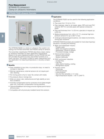
Description3.13FST020 featuresDescriptionThe Siemens SITRANS FST020 IP65 NEMA 4X flow meters achieve highly accurate flowmeasurement owing to the WideBeam ultrasonic transit-time technology. The sensors aremounted on the outside of the pipe, preventing contact with the medium.The sensor construction makes installation and commissioning of even the largest sizes verystraight forward and easy. The sensors deliver true multi parameter measurements i.e.volume flow.NoteThis Operating Instructions manual applies to the following FST020 IP65 NEMA 4Xoperating systems: Version 2.04.04 and later.3.2NEMA 4X TransmittersSITRANS FST020 TransmittersThe SITRANS FST020 NEMA 4X series transmitters are available in AC or DC poweredversion
Operating Instructions Edition 8/2014 Answers for industry. Ultrasonic Flowmeters SITRANS FST020 IP65 NEMA 4X - 7ME3570 SITRANS F