Transcription
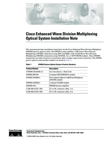
1360IEEE JOURNAL ON SELECTED AREAS IN COMMUNICATIONS, VOL. 20, NO. 7, SEPTEMBER 2002A Multiplexing Scheme for H.323 Voice-Over-IPApplicationsH. P. Sze, Soung C. Liew, Senior Member IEEE, Jack Y. B. Lee, and Danny C. S. YipAbstract—Voice communications such as telephony are delaysensitive. Existing voice-over-IP (VoIP) applications transmit voicedata in packets of very small size to minimize packetization delay,causing very inefficient use of network bandwidth. This paperproposes a multiplexing scheme for improving the bandwidthefficiency of existing VoIP applications. By installing a multiplexerin an H.323 proxy, voice packets from multiple sources arecombined into one IP packet for transmission. A demultiplexer atthe receiver-end proxy restores the original voice packets beforedelivering them to the end-user applications. Results show thatthe multiplexing scheme can increase bandwidth efficiency by asmuch as 300%. The multiplexing scheme is fully compatible withexisting H.323-compliant VoIP applications and can be readilydeployed.Index Terms—Internet telephony, multiplexing, voice over IP.I. INTRODUCTIONTHE DEVELOPMENT and expansion of the Internet in thelast few years are making it possible for real-time voicetraffic to reach many different corners of the world. Althoughthe Internet was not originally designed for real-time communications, Internet telephony is becoming one of the fastestgrowing application areas for the Internet today [1]. With thedeployment of quality-of-service (QoS)-capable network components, the primary hindrance to voice over IP (VoIP) can beovercome and its proliferation will be almost certain in the nearfuture [2].The tremendous growth of Internet telephony is driven byits several fundamental benefits over traditional public switchedtelephone network (PSTN). First of all, from the user’s point ofview, making long-distance calls via the Internet results in substantial cost reduction since international toll charge imposed bytelecommunication companies are bypassed. In addition, voicecommunication can be enhanced with other media and data applications like video, white boarding, and file sharing. Some ofManuscript received May 1, 2001; revised January 7, 2002. This work wassupported in part by the Area of Excellence in Information Technology of HongKong: Project AoE/E-01/99.H. P. Sze was with the Department of Information Engineering, Chinese University of Hong Kong, Shatin, N.T., Hong Kong and a Consultant with RoctecTechnology Ltd. He is now with Hong Kong Applied Science and TechnologyResearch Institute, Kowloon, Hong Kong (e-mail: sze@astri.org).S. C. Liew and J. Y. B. Lee are with the Department of Information Engineering, Chinese University of Hong Kong, Shatin, N.T., Hong Kong (e-mail:soung@ie.cuhk.edu.hk; jacklee@computer.org).D. C. S. Yip was with the Department of Information Engineering, ChineseUniversity of Hong Kong, Shatin, N.T., Hong Kong. He is now a Consultantwith Accenture Company Limited, Hong Kong (e-mail: dyip@hongkong.com).Publisher Item Identifier 10.1109/JSAC.2002.802064.these add-on features have already been implemented in software applications such as NetMeeting [3].From the network operator’s viewpoint, IP telephony canhave two substantial bandwidth advantages. First, advancedvoice-compression techniques [4], can be used to reduce thedata rate of a call. A 64-Kb/s channel in a PSTN call can beused to accommodate several IP-based telephony calls, whichconsumes less than 10 Kb/s each with a slight degradation invoice quality. Second, voice delivery over IP network itselfcan achieve higher efficiency as compared with PSTN. Specifically, with circuit switching in PSTN, a dedicated channel isreserved over the whole duration of a call, whereas with thepacket-switched Internet, bandwidth is consumed only whenvoice packets are delivered.In spite of the advantages, voice over the Internet has severallingering challenges. Apart from the potential QoS problem, onekey issue is the inefficient use of bandwidth in high-cost widearea network (WAN), namely the access links of enterprise network, due to packet header overhead (although efficiency is already much better than the use of PSTN). For example, a typical IP voice packet consists of a header of 40 bytes. Comparedwith the typical payload size of only 10–30 bytes for each audioframe, the header overhead is clearly very substantial.Current VoIP applications tackle this problem by embeddingmultiple audio frames into a single packet at the source to increase the ratio of payload to header size [6]. This approach hasthe benefit of reducing the overall data rate of a call. However,since an audio frame is generated only after raw audio signalsin a frame period are captured and encoded, packing an additional audio frame will add another frame period to the assemblydelay. Together with the existing network delay, the resultantend-to-end delays may become unacceptable.Obviously, maintaining a short delivery time of data is essential in interactive applications like telephony. In particular,the ITU Recommendation G.114 [7] gives guidelines on thetolerable delay for a normal telephone conversation. The maximum one-way end-to-end delay acceptable by most users isonly 150 ms. A telephony system with longer end-to-end delayswill cause users to engage in collided talks and mutual silencesmore often [8]. To balance conversation quality and network efficiency, a compromise must be made between packet delay andheader overhead. Such a tradeoff is illustrated by Fig. 1, in whicha G.723.1 codec is assumed.In this paper, we present a novel voice multiplexing schemewhich makes it possible to circumvent the above tradeoff toachieve low end-to-end delay and high bandwidth efficiencysimultaneously. In particular, our solution aims for bandwidthefficiency on a shared long-distance link used to transport the0733-8716/02 17.00 2002 IEEE
SZE et al.: A MULTIPLEXING SCHEME FOR H.323 VOIP APPLICATIONS1361H.323 entity on the network that provides address translation,access control for terminals, and optionally, call routing for signaling and control messages. All these features are essential toour scheme and are adopted in the call-establishment proceduresof the multiplexing system.C. RTP/UDP/IP Header CompressionFig. 1. Tradeoff between bandwidth efficiency and assembly delay withG.723.1.voice packets. Audio frames from various sources are transmitted on a shared IP packet in our scheme to reduce headeroverhead.II. BACKGROUNDIn this section, we review current VoIP standards that are relevant to our work, including speech codec, H.323 communications protocol, and RTP/UDP/IP header compression.Real-time transport protocol (RTP) provides end-to-end network transport functions needed for applications transmittingreal-time data [14]. It is now being used by various networkapplications, including H.323, for delivery of media stream.Since RTP packets transmitted over the Internet carry a 40-byteRTP/UDP/IP header, the header overhead will become verysubstantial for packets with small payload size (e.g., 10 bytesin G.729A at 1 frame/packet). Thus, to increase the bandwidthutilization and minimize the end-to-end packet delay, Casnerand Jacobson have proposed an RTP/UDP/IP header compression scheme for low-speed serial links [15]. Their workhas successfully reduced the RTP/UDP/IP header size from40 bytes to a minimum of 2 bytes on a link-by-link basis. Basedon similar principles, we designed a similar but simplifiedcompression scheme for use in the RTP application layer (asopposed to the link layer in the original case) to minimize theheader length of audio chunks from different sources inside amultiplexed packet so as to increase the bandwidth efficiency.A. Speech CodecD. Related WorkThe primary functions of a speech codec are to performanalog/digital voice signal conversion and digital compression. Three commonly used codecs in Internet telephony areGSM 6.10 [9], G.723.1 [10], and G.729A [11]. Table I summarizes the main attributes of these codecs. One observationis that all three codecs generate audio frames at a constantbit-rate. When silence suppression scheme is employed, thecodecs then operate in two states: a silent state at zero bit-rate(or lower bit-rate in some other codecs) and an active stateat the compressed bit-rate. Regardless of the state, the frameperiod and frame size are still fixed. This characteristic allowsus to simplify the design of our multiplexing scheme, to bediscussed in Section III-B.The idea of multiplexing multiple voice streams has alsobeen investigated by other researchers. Hoshi [16] proposeda multiplexing system for use between H.323 IP-telephonygateways to reduce the number of RTP packets transportedover the IP network. His multiplexer improves transmissionefficiency by concatenating voice packets from differentstreams into a single UDP packet for transmission. But unlikethe multiplexing scheme studied in this paper, their scheme didnot compress the RTP headers.More recently, IETF is working on a multiplexing scheme forRTP streams [17]. Rather than integrating voice-multiplexingtechnique with the existing VoIP systems, their work combinedthe aforementioned RTP/UDP/IP compression standard withanother point-to-point protocol (PPP) multiplexing scheme[18] to form a generic method for end-to-end tunneling ofmultiplexed RTP packets. Their proposed scheme operates inthe link layer and can only be used over PPP links.B. The H.323 StandardTwo major standards are emerging in the industry for VoIP:the ITU-T Recommendation H.323 [12] and the session initiation protocol (SIP) [13] from Internet Engineering Task Force(IETF). Being the earlier of the two standards, H.323 has received wider adoption in the industry since its first release in1996. VoIP product vendors such as Cisco Systems, Microsoftand VocalTec all support this standard in their VoIP applications. For this reason, we design our multiplexing scheme to becompatible with the H.323 standard so that existing H.323-compliant applications can be seamlessly supported.H.323 is known as an umbrella recommendation as it refersto other standards in its system description. Its main specifications include call signaling, media-channel signaling, and mediatransportation. It also introduces an important component wherewe implement our system—the gatekeeper. Gatekeeper is anIII. VOIP MULTIPLEXING SCHEMEWe present in this section the design of the proposed VoIPmultiplexing scheme and discuss how it can be integrated intothe H.323 framework to maintain compatibility with existingH.323 applications. The design of the multiplexer is motivatedby two observations. First, bandwidth at a local network [e.g.,corporate local area network (LAN)] is usually abundant and,hence, efficient bandwidth usage is not a major concern. Second,multiple local networks are often connected via one or moreWAN links with more expensive and limited bandwidth. TheseWAN links are the bottleneck and, hence, bandwidth efficiencyis critical. The proposed multiplexer addresses this challenge by
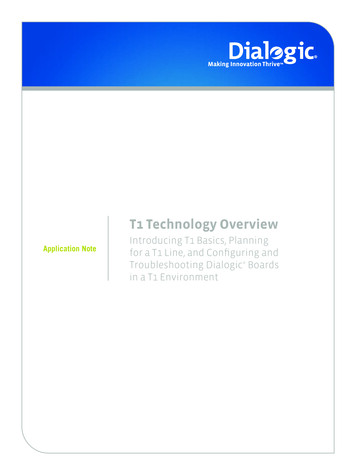
1362IEEE JOURNAL ON SELECTED AREAS IN COMMUNICATIONS, VOL. 20, NO. 7, SEPTEMBER 2002TABLE ITHE ATTRIBUTES OF THREE COMMON SPEECH CODECSFig. 2. System architecture.multiplexing and compressing voice packets before transmittingthem over the WAN links. The following sections present themultiplexing algorithm, the header compression scheme, andthe connection management protocol.A. Packet MultiplexingAs bandwidth in local networks is abundant, VoIP applications can send each audio frame in a separate RTP packetto minimize packetization delay. For voice traffic to be transported over the same WAN link, they go through a multiplexer(MUX) located at the sender-side network, and a demultiplexer(DEMUX) located at the receiver-side network. The MUX replaces the RTP header of each voice packet with a compressedminiheader and then aggregates multiple packets into a singlemultiplexed packet. All these chunks share a common UDP/IPheader and are then sent to the DEMUX across the WAN link.On the receiver-side network, the DEMUX inspects the miniheaders inside each multiplexed packet, restores the originalRTP headers and destination information, and reconstructsthe individual voice packets for delivery to their respectivereceivers. The system architecture is illustrated by Fig. 2.To control packet delay, the MUX sends out a multiplexedpacket every ms, which is equal to or shorter than the audioframe period, denoted by ms. Larger value of can improvebandwidth efficiency for more streams can be multiplexed butthe delay incurred will also be larger. Hence, by adjusting ,one can control the tradeoff between bandwidth efficiency and, whereis thedelay. In addition, by settingframe period of the th source, the multiplexing system can alsobe applied to situations where senders are using speech codecswith different frame periods.The previous multiplexing policy ensures that the extra delayincurred in the MUX is bounded by one frame period. Moreover,since at most one audio frame from each source is stored in anaggregated packet, the design of our scheme is simplified bythe limitation of only one possible payload size in each chunkof a source embedded in the aggregated packets. Alternatively,the MUX may also generate a multiplexed packet before msexpires if the amount of accumulated payload has reached themaximum transfer unit (MTU) of the link layer of the WANtrunk. This can avoid increasing the packet-loss probability dueto fragmentation of the multiplexed packets in the WAN link.B. RTP Header CompressionApart from aggregation, we also increase the bandwidth efficiency of multiplexed voice traffic by compressing the packetheaders during multiplexing. As mentioned in the previous section, the compression algorithm in our scheme draws upon theideas of RTP/UDP/IP header compression described in [15],with features optimized for VoIP applications, discussed below.Casner’s algorithm takes advantage of two properties in mosttypes of RTP streams. The first is that most of the fields in the IP,UDP and RTP headers do not change over the lifetime of an RTPsession. These constant-value fields can be represented by fewerbits with a session context during transmission. Second, RTPheader fields like sequence number and timestamp are increasedby a constant amount for successive packets in a stream. Hence,differential coding can be applied to compress these fields intofew bits.Combining the previous techniques, Casner managed to compress the header size down to two bytes in the best case (onecondition, e.g., is that UDP checksum from the source is disabled) but the scheme relies on the link layer for exchangingcontrol messages. While this scheme offers a full restoration ofthe RTP/UDP/IP header, we incorporate a simplified version ofit into our application-layer scheme to suit voice traffic and recover only the necessary header fields for lossless playback ofvoice data at receiver. In this way, 2-byte header compressioncan be achieved for most voice packets in a RTP stream withoutthe support of the link layer, making it possible to apply ourscheme at the network layer in which packets may traverse several links.As long as the packets can be transported to the correct destination, the fields in the UDP/IP header which do not need to
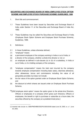
SZE et al.: A MULTIPLEXING SCHEME FOR H.323 VOIP APPLICATIONS1363TABLE IIDIFFERENT ATTRIBUTES IN MUX/DEMUX TABLES(a) Channel table in MUX/DEMUX.(b) Context-mapping table for a particular channel ID in MUX.(c) Context-mapping table for a particular channel ID in DEMUX.be recovered are source IP, port number, IP packet ID and UDPchecksum. For successful delivery, two important elements tobe reconstructed during decompression in our scheme are destination IP address and port number. The fields in the RTP headerare all reconstructed to preserve the timing information of theaudio payloads.Our compression mechanism depends on the use of context-mapping tables in both MUX and DEMUX. These tablesrecord necessary information for proper (de)compression and(de)multiplexing. The different attributes in the MUX/DEMUXtables are shown in Table II. Since a MUX can simultaneouslywork with multiple DEMUX’s and vice versa, a particularmultiplexed channel is identified by the combination of MUXIP, DEMUX IP and DEMUX receiving port number. Eachchannel has a unique ID and context-mapping table. In addition,with the 1-byte-long session context identifier (CID), eachchannel can accommodate at most 256 sessions. Thus, usingseveral DEMUX ports, multiple channel IDs can be assignedto a MUX/DEMUX pair to increase the number of sessionsby handling several virtual multiplexed channels on the samephysical channel.Three types of miniheaders are used in the compression.COMPRESSED is a fully compressed RTP header. SYNCHRONIZATION is a compressed RTP header with sequencenumber and timestamp. UNCOMPRESSED contains a fullRTP header. Their formats are shown in Fig. 3.The header compression process is as follows. When a callis made between two regions, an entry with a unique CIDis inserted into the tables in both the MUX and DEMUXduring the H.323 connection establishment stage, which willbe detailed later in this paper. Afterwards, the MUX willbegin to receive voice packets in the RTP session from thissource. Upon receiving a packet, the MUX will first searchfor a matched session context by the primary key—source IPaddress, port number, and RTP SSRC identifier inside eachchannel’s context-mapping table until a correct multiplexedchannel (or DEMUX) and CID can be found. For the first few(a)(b)(c)Fig. 3. Formats of three types of miniheaders. (a) UNCOMPRESSEDminiheader. (b) SYNCHRONIZATION miniheader. (c) COMPRESSEDminiheader.RTP packets from the source, they will be embedded in themultiplexed packets with the UNCOMPRESSED miniheader(without RTP header compression). This is for the DEMUX tofill in the fields in its context-mapping table like RTP Header,Time Difference, and Last Synchronization. After that, if theRTP header fields in subsequent packets can fulfill the criteriaof compression (i.e., constant changes in the timestamp andsequence number, and no changes in the constant RTP fields),a 2-byte COMPRESSED miniheader, which consists of a CIDand context sequence number (CSEQ), will replace the 12-byteRTP header at the MUX. The CSEQ is calculated from thedifference between the RTP sequence number in the receivedpacket and the one updated in the MUX table entry in the previous MUX/DEMUX synchronization. On the demultiplexingside, by checking the receiving port and the CID of a voice
1364IEEE JOURNAL ON SELECTED AREAS IN COMMUNICATIONS, VOL. 20, NO. 7, SEPTEMBER 2002TABLE IIIAN EXAMPLE OF CONTEXT MAPPING TABLES(a) Example of a context-mapping table in MUX.(b) Example of a context-mapping table in DEMUX.chunk embedded in a multiplexed packet, a DEMUX can lookup a matched entry in its tables. It then reconstructs the constantRTP fields from the stored RTP Header attribute. To recoverthe changing RTP fields, it adds multiple of the first-orderdifferences to the saved RTP sequence number and timestampduring last synchronization according to the CSEQ inside theminiheader.For better illustration, we demonstrate this idea by an example. Assume at a particular moment, the context mapping tables in MUX and DEMUX contain the information as shown inTable III.Now, suppose the MUX receives an RTP packet withsequence number and timestamp equal to 43 and 14 230,respectively. It computes the CSEQ for the COMPRESSEDminiheader as follows:CSEQLast Sync. RTP Seq. No.Last Sync. CSEQAs a result, the MUX embeds the voice chunk stamped withCSEQ 5 into its multiplexed packet. When this packet arrivesat the DEMUX, a record is found for this payload and the original varying RTP fields is regenerated by the following computations:RTP Seq. No.CSEQLast Sync. CSEQLast Sync. RTP Seq. No.TimestampCSEQLast Sync. CSEQTime DifferenceLast Sync.TimestampOther constant RTP fields can also be recovered since theyhave already been stored in the DEMUX table. Nevertheless,when the MUX receives a packet with the second-order difference of RTP timestamp not equal to zero (e.g., the packet received at the start of a talkspurt with a codec that outputs zerobit during silent state), the DEMUX cannot restore the originaltimestamp from the COMPRESSED miniheader. Accordingly,Fig. 4.Connection procedures.a synchronization miniheader, which carries the RTP sequencenumber and timestamp, will be sent instead. Furthermore, sincethe four-bit CSEQ in a miniheader produces a sequence-numbercycle of 16 packets, this synchronization miniheader will alsobe transmitted by the MUX once every 16 packets for each RTPstream.In our miniheaders, there are one State ( ) bit and one Marker( ) bit. With codecs operating with two-state variable bit-rates,the DEMUX can derive the bit-rate of an RTP stream from thebit and, hence, the payload size after the miniheader of a particbit is an RTPular voice chunk in a multiplexed packet. Thefield that is set to one in the first packet of a talkspurt. This bitmust be carried to the DEMUX for complete restoration of theRTP header.C. Connection EstablishmentThe H.323 standard specifies the process of connection setupin a phone call over a packet network. The main phases includeregistration/admission signaling (RAS), Q.931 call signaling,and H.245 media channel signaling. To ensure that any H.323clients can readily use our multiplexing system to make callswithout modification, we embed our connection establishmentprocedures for multiplexing into the H.323 calling process. Forseamless incorporation, our MUX/DEMUX will act as an H.323gatekeeper as well. All the steps required for establishing themultiplexing channel are transparent to the clients. Depicted byFig. 4, the whole connection procedures are as follows.1) The H.323 initiator registers at MUX A and sends it anAdmission Request (ARQ) carrying the alias of the H.323acceptor.2) MUX A searches for the acceptor by broadcasting a Location Request (LRQ) to its MUX neighborhood, includingMUX B.
SZE et al.: A MULTIPLEXING SCHEME FOR H.323 VOIP APPLICATIONS13653) Assuming the called party is currently logging intoMUX B, MUX B will reply MUX A with a LocationConfirm (LCF). For routing the signaling messagesthrough MUX B, its LCF carries its own Call SignalingChannel Transport Address instead of the original calledparty.4) MUX A sends an Admission Confirm (ACF) to the initiator, with the Transport Address set to itself instead ofMUX B.5) The endpoints exchange call signaling and H.245 controlmessages through the MUXs.6) However, when MUX B receives the OpenLogicalChannelAck (ACK) message from the acceptor, which containsthis endpoint’s destination IP address and port number forthe RTP stream from the initiator, MUX B stores thesetwo fields in a new entry of its DEMUX table and replacesthem in the ACK with its IP address and the receiving portof this multiplexed channel. Meanwhile, a unique CIDis assigned to the RTP stream and is embedded into anextra and optional portNumber field in the ACK, whichis not used originally. This message is then forwarded toMUX A.7) When MUX A receives this modified message, it alsocreates a new entry in its MUX table with the specifiedCID. After that, it records the DEMUX IP and receivingport in the channel table if needed and replaces them inthe ACK with its IP address and receiving port for theRTP source.8) The initiator receives the ACK from MUX A and startstransmitting voice packets to it with the given IP addressand port number. [Step 6)–8) will be repeated in the opposite direction when the initiator feeds back an ACK tothe acceptor through the MUXs for establishing an RTPsession from the acceptor to initiator.]After successful connection setup, the first few voice packetsfrom this particular source will not be compressed when it isbeing multiplexed with the voice chunks from other sources sothat the remaining fields in the DEMUX table entry of MUX Bcan be filled in. After that, MUX A will then compress and multiplex the RTP packets headed for the acceptor by maintainingthe CID and the multiplexed channel negotiated during startup.IV. PERFORMANCE ANALYSISIn this section, we analyze the performance of the proposedmultiplexing scheme using three performance metrics, namelybandwidth efficiency, capacity, and delay.A. Bandwidth EfficiencyWe first compare the bandwidth efficiency in the IP layer ofthe proposed multiplexing scheme to the conventional nonmultiplexed approach. The efficiency of a WAN link connecting theproposed MUX and DEMUX can be calculated frompayload sizeIP packet size(1)where is the audio-payload size,is the COMPRESSEDis the UDP/IP header sizeminiheader size (2 bytes),(28 bytes), and is the number of voice streams multiplexed.1For the conventional method without multiplexing, the transmission efficiency is given bypayload sizeIP packet size(2)is RTP/UDP/IP header size (40 bytes).whereAs an illustration, take the common G.729A codec whichgenerates voice packets at a rate of 8 Kb/s as an example. Theaudio-frame size is equal to 10 bytes and, hence, if each RTP0.2.packet from the source carries one frame, we getIn other words, 80% of the bandwidth is used for deliveringheaders instead of voice data.Using our multiplexing scheme, suppose there are 45 simultaneous calls in active state (i.e., sending voice data), then thebecomes 0.792. Comparing to the nonmultiefficiencyplexed approach, our multiplexing scheme increased bandwidthefficiency by almost 300%.B. CapacityKnowing the bandwidth requirement and available channelcapacity, we can then compute the maximum number of voicestreams that can be accommodated. Assuming the capacity islimited by available bandwidth, then we can determine the numbers of concurrent streams using the following inequality:Aggregated voice data rateavailable bandwidth(3)Suppose all transmitters use the same codec with a frame periodof ms. For the proposed scheme, the multiplexing period willbe equal to one frame period, and the inequality becomes(4)where is the audio-frame size and is the WAN-link bandwidth in bps. Without multiplexing, the inequality becomes(5)where is the audio frame-to-packet ratio.10 andAgain, using G.729A for comparison (i.e.,10). Consider a T1 link of 1.5-Mb/s bandwidth. Thenour multiplexing scheme can accommodate up to 153 streamsaccording to (4). By contrast, the nonmultiplexed approach canaccommodate only 37 streams with one audio frame per RTPpacket. With two audio frames per RTP packet, the number ofstreams increases to 62, which is still only 40% of the capacityachieved by our multiplexing scheme.C. DelayThe tradeoff in achieving higher bandwidth efficiency usingmultiplexing is delay. Specifically, two types of delay are incurred by the multiplexing scheme: additional packet processingtime at the router and packet waiting time at the MUX. Since1The effect of periodical transmission of SYNCHRONIZATION miniheaderon efficiency is insignificant and is omitted in the derivations.
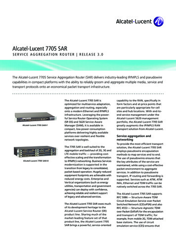
1366IEEE JOURNAL ON SELECTED AREAS IN COMMUNICATIONS, VOL. 20, NO. 7, SEPTEMBER 2002Fig. 5. Network scenario in simulations.the router store-and-forward delay is proportional to the packetlength and inversely proportional to the link speed, the largermultiplexed packets will introduce a longer transmission delaythan normal voice packets. But because the multiplexed-packetlength is bounded by the MTU, this store-and-forward delay isat most 3 ms for a typical T1-speed link with MTU 576 bytes.A voice packet will also encounter an extra delay at the MUXwhen it needs to wait a certain amount of time before the MUXgenerates a multiplexed packet. Since we set the multiplexingperiod to one audio-frame period and the MUX may alternatively send a packet when the number of voice chunks collectedis adequate for transmission, this delay is bounded by one frameperiod. Because senders need not worry about the bandwidth efficiency at the WAN trunk with the multiplexing feature, theycan simply transmit one audio frame in every RTP packet tominimize the overall packet latency. As a result, the delay incurred at the source is one frame period. Since the processingtime of MUX and DEMUX is insignificant, the total delay introduced by our system is limited by about two frame periods. Thisamount of latency is close to the conventional scheme transmitting 2 frame/packet at the source but our scheme can offer amuch higher bandwidth efficiency when there are many voicestreams.V. SIMULATION RESULTSWe carry out simulations to study the performance of oursystem. Our goal is to compare the results with the conventionalschemes in terms of packet delay and number of calls supported.A. Network and Source ModelThe network model in our simulations consists of two localities connected together with a WAN link of limited bandwidth, one containing senders and the other receivers. Thesenders are assumed to connect to a common MUX via an infinitely fast link in a LAN. The receivers are assumed to connect to a common DEMUX via an infinitely fast link in anotherLAN. The WAN trunk is modeled as a first-in first-out (FIFO)and a fixed buffer size. Incomingqueue with service ratepackets are discarded when the buffer overflows. The scenariois shown in Fig. 5. The MUX multiplexes the RTP packets fromsenders every ms which is equal to one audio-frame period orwhen the multiplexed packet is full according to the link layerMTU of the WAN which is 576 bytes in our simulations. Consequently, the MUX introduces a variable delay to every packetFig. 6. Comparison of overall delay and WAN link utilization betweenconventional schemes and proposed scheme.from senders. The propagation times and processing times ofMUX/DEMUX and receivers are assumed to be negligible.We assume that voice silence suppression is activated in thecodecs and, there
voice quality. Second, voice delivery over IP network itself can achieve higher efficiency as compared with PSTN. Specif-ically, with circuit switching in PSTN, a dedicated channel is reserved over the whole duration of a call, whereas with the packet-switched Internet, bandwidth is consumed only when voice packets are delivered.