Transcription
2012British ColumbiaPlumbing CodeUpdate
2012 British Columbia Plumbing Codeis published as a separate documentand is broken down into Divisions similar to BCBC2
Division APart 1 – CompliancePart 2 – ObjectivesPart 3 – Functional StatementsAppendix A (Division A)3
A-1.4.1.2.(1) Defined TermsAuxiliary Water Supply – expanded to include: Harvested or recovered rainwater commonly refers to atype of auxiliary water supply that is collected fromexternal surfaces of buildings or other hard-surfacedareas not exposed to vehicular or pedestrian traffic.Auxiliary water supply that meets the definition ofpotable water can be used to supply potable watersystems. Auxiliary water supply that doesn’t meet thedefinition of potable water can be used to supply nonpotable water systems.Division AAppendix A4
Division BPart 1 – GeneralPart 2 – Plumbing SystemsAppendix A (Division B)5
1.3.1.2. Applicable Editions1) Where documents are referenced in this Code, theyshall be the editions designated in Table 1.3.1.2.Referenced Editions of Documents and Standardshave been updatedexample NFPA 13D-2007Division BPart 16
Numbering harmonized with National Plumbing CodeNo longer located in Div B Part 7Sentence 7.6.1.3 Shut-off Valves – 2006 BCPCis nowSentence 2.6.1.3 Shut-off Valves – 2012 BCPC7
Part 2 Plumbing SystemsSection 2.1 – GeneralSection 2.2 – Material and EquipmentSection 2.3 – PipingSection 2.4 – Drainage SystemsSection 2.5 – Venting SystemsSection 2.6 – Potable Water SystemsSection 2.7 – Non-Potable Water SystemsSection 2.8 – Objectives and Functional StatementsAppendix A (Division B)8
2.1.2.1. Sanitary Drainage Systems1) Except as provided in Subsection 2.7.4., every sanitarydrainage system shall be connected to a public sanitarysewer, a public combined sewer or a private sewagedisposal system.2.7.4.1. Non-potable Water System DesignClarifies that non-potable water systems are permitted.Division BPart 29
Also applies to 2.1.2.2. – Storm Drainage Systems2.1.2.3. – Water Distribution SystemsEach of these sentences starts with the wording “Except asprovided in Subsection 2.7.4.,”Division BPart 210
2.2.5.13. Polyethylene/Aluminum/Polyethylene CompositePipe and Fittings2) Except as provided in Sentences (3) and (4), PE/AL/PEpipe and fittings shall not be used in hot water systems.3) PE/AL/PE pipe with a pressure rating of 690 kPa orgreater at 82 C shall be permitted for hot water systems.Division BPart 211
4) PE/AL/PE pipe with a pressure rating of 690 kPa orgreater at 82 C shall be used with fittings that conformto CAN/CSA-B137.10, “CrosslinkedPolyethylene/Aluminum/Crosslinked Polyethylene (PEXAL-PEX) Composite Pressure-Pipe Systems,” in hot watersystems.Division BPart 212
2.2.10.6. Supply and Waste Fittings1) Supply fittings shall conform toa) ASME A112.18.1/CAN/CSA-B125.1 “Plumbing Supplyfittings” orb) CAN/CSA-B125.3 “Plumbing Fittings.”2) Waste fittings shall conform toASME A112.18.2/CAN/CSA-B125.2. “Plumbing WasteFittings”.Division BPart 213
2.2.10.7. Water Temperature Control(See Appendix A.)1) Except as provided in Sentence (2), all valves supplyingfixed-location shower heads shall be individual pressurebalanced or thermostatic-mixing valves conforming to ASMEA112.18.1/CAN/CSA-B125.1, “Plumbing Supply Fittings.”2) Individual pressure-balanced or thermostatic-mixing valvesshall not be required for showers having a single temperedwater supply that is controlled by a master thermostaticmixing valve conforming to CAN/CSA-B125.3, “PlumbingFittings.”Division BPart 214
2.2.10.7. Water Temperature Control (cont.)3) All mixing valves supplying shower heads shall be of thepressure-balanced, thermostatic, or combinationpressure-balanced/thermostatic type capable ofa) maintaining a water outlet temperature that does notexceed 49 C, andb) limiting thermal shock.4) The temperature of water discharging into a bathtubshall not exceed 49 C.Division BPart 215
A-2.2.10.7. Hot Water TemperatureHot water delivered at 60 C will severely burn human skinin 1 to 5 seconds. At 49 C, the time for a full thicknessscald burn to occur is 10 minutes. Children, the elderlyand persons with disabilities are particularly at risk ofscald burns. Compliance with Article 2.2.10.7. will reducethe risk of scalding in showers and bathtubs, and reducethe risk of thermal shock from wall-mounted showerheads.Division BAppendix16
These requirements apply to all occupancies, not justresidential occupancies.The water outlet temperature at other fixtures, such aslavatories, sinks, laundry trays or bidets, is not addressedby Article 2.2.10.7., but a scald risk may exist at suchfixtures nonethelessDivision BAppendix17
2.2.10.14. Vent Pipe Flashing1)Flashing fabricated on-site for vent pipes shall befabricated fromb) aluminum sheet not less than 0.48mm thickd) lead sheet not less than 1.73mm thicke) galvanized steel sheet not less than 0.33mm thickDivision BPart 218
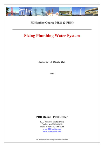
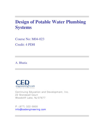
2.4.2.1. Connections to Sanitary Drainage Systems4) Where a change in direction of more than 45 degreesoccurs in a soil-or-waste pipe that serves more than oneclothes washer, and in which pressure zones are createdby detergent suds, no other soil-or-waste pipe shall beconnected to it within a length less thana) 40 times the size of the soil-or-waste pipe or 2.44 mmaximum vertical, whichever is less, before changingdirection, andb) 10 times the size of the nominally horizontal soil-orwaste pipe after changing direction.(See Appendix A.)Division BPart 219
2.4.2.1. Connections to Sanitary Drainage Systems (cont.)5) Where a vent pipe is connected into the suds pressurezone referred to in Sentence (4), no other vent pipe shallbe connected to that vent pipe within the height of thesuds pressure zone. (See A-7.4.2.1.(4) in Appendix A.)Division BPart 220
Figure A-2.4.2.1.(4) SudsPressure ZonesDivision BAppendix21
Table 2.4.9.3.Minimum Permitted Size of Fixture Outlet Pipe andHydraulic Loads for FixturesClothes washer(a) domestic(b) commercialMacerating toiletsystemMin/sizen/an/a¾”Hydraulic Load, Fixture Units2 with 2-in. trap2 with 2-in. trap4Division BPart 222
2.4.10.4. Hydraulic Loads from Roofs or Paved Surfaces2) Flow control roof drains may be installed provideda) the maximum drain down time does not exceed 24 h,b) the roof structure is designed to carry the load of thestored water,c) one or more scuppers are installed not more than 30 mapart along the perimeter of the building so thati) up to 200% of the 15-minute rainfall intensity can behandled, andii) the maximum depth of controlled water is limited to 150Division Bmm,Part 223
2.4.10.9. Hydraulic Loads on Storm or Combined BuildingDrains or Sewers - Table 2.4.10.9Table 2.4.10.9.Maximum Permitted Hydraulic Load Drained to a Storm Building Drain or Sewer or a Combined Building SewerForming part of Article 2.4.10.9.Size ofMaximum Hydraulic Load, LDrain orSlopeSewer,1 in 400 1 in 200 1 in 133 1 in 100 1 in 68 1 in 50 1 in 25inches3————23902 770 3 9104———4 2205 1605 970 8 430Division BPart 224
2.5.2.1. Wet Venting1) A soil-or-waste pipe may serve as a wet vent providedthata) the hydraulic load is in accordance with Table 2.5.8.1.,Table 7.5.2.1. (Sizing of Wet Vents in 2006 Code) has beenremoved from the 2012 Code and all references to Table7.5.2.1 have been changed to 2.5.8.1)Division BPart 225
2.5.2.1. Wet Venting1) A soil-or-waste pipe may serve as a wet vent providedthatg) the hydraulic load of separately vented fixtures thatdrain into the wet vent are not included when sizing thecontinuous vent that serves the wet vent,( rewording of the clause means the same as before )Division BPart 226
2.5.4.2. Vent Stacks1) Except as provided in Sentence (2), every soil-or-wastestack draining fixtures from more than 4 storeys shallhave a vent stack.Division BPart 227
2.5.8.3. Branch Vents, Vent Headers, Continuous Vents andCircuit Vents1)Branch vents, vent headers, circuit vents andcontinuous vents shall be sized in accordance withTable 2.5.8.3., unless they are individual vents or dualvents.The size of individual vents and dual vents shall bedetermined using Table 2.5.7.1. based on the largesttrap servedDivision BPart 228
2.5.8.4. Vent Stacks or Stack Vents – Table 2.5.8.4Table 2.5.8.4.Size and Developed Length of Stack Vents and Vent StacksSize or Soil-orwaste stack,inches(1)Total Hydraulic Size of Stack Vent or Vent Stack, inchesLoad Being Vented, 1¼ 1½ 2 3 4 5 6 8 10 12fixture unitsMaximum Length of Stack Vent or Vent Stack, m1¼291½8154610930.512923612481546101346 3172110 33.5 24723Not LimitedDivision B Part 229
2.6.1.12. Service Water Heaters1) Thermostat controls for electric storage-type servicewater heaters shall be set at a temperature of 60 C. (SeeAppendix A.)Division BPart 230
A-2.6.1.12.(1) Service Water HeatersStoring hot water at temperatures below 60 C in the hotwater tank or in the delivery system may lead to thegrowth of legionella bacteria. Contemporary electric waterheater tanks experience temperature stratification andthus tend to have legionella bacteria in the lower parts ofthe tank.Division BAppendix31
A-2.6.1.12.(1) Service Water Heaters (cont.)Article 2.6.1.12. specifies a thermostat setting of60 C, which addresses the concern over the growth oflegionella bacteria in electric hot water storage tanksand is enforceable without introducing unnecessarycomplications. The growth of legionella bacteria is not aconcern for other types of water heaters with differentdesigns that use different fuels.Division BAppendix32
2.6.3. Size and Capacity of Pipes2.6.3.1. Design, Fabrication and Installation1) Every water distribution system shall be designed toprovide peak demand flow when the flow pressures atthe supply openings conform to the plumbing supplyfitting manufacturer’s specifications.Division BPart 233
A-2.6.3.1.(2) Potable Water SystemsThe design procedures contained in the followingdocuments are considered good engineering practice inthe field of potable water systems:a)ASHRAE 2003, “ASHRAE Handbook of HVAC Applications,” chapter on Service WaterHeating,b)ASHRAE 2009, “ASHRAE Handbook of Fundamentals,” chapter on Pipe Sizing,c)ASPE 2005, “ASPE Plumbing Engineering Design Handbook,” chapter on Cold WaterSystems, andd)ASPE 2005, “ASPE Plumbing Engineering Design Handbook,” chapter on DomesticWater Heating Systems.Division BAppendix34
A-2.6.3.1.(2) Potable Water Systems (cont.)Alternatively, the following methods, which apply to both publicand private water supplies, may be used in determining the sizeof each section of the water system using Table A-2.6.3.1.(2)A (Small Commercial Building Method) and Table A-2.6.3.1.(2)F (Average Pressure Loss Method).Where these methods are considered an alternative to adetailed engineering design method, the hydraulic loads shall bethe sum of the total fixture units given in Tables 2.6.3.2.A, B,C and D.Division BAppendix35
Average Pressure Loss MethodSizing based on a single table designed for watervelocities of 3.0, 2.4 and 1.5m/s.‘Total equivalent length’ required for calculations.Fixture unit values for fire sprinkler system, irrigationsystem and any other similar demands must be addedon to water service load.Division BAppendix36
Table A-2.6.3.1.(2)FAverage Pressure Loss MethodDivision BAppendix37
Average Pressure Loss Method (cont.)Pressure losses from devices, meters and elevation mustbe taken into consideration.Designed for use in larger commercial, but can be usedfor any size building.To use this method, calculate the pressure available forfriction loss which must be 2.6 kPa per metre or more; ifit is less than that, the system must be designedaccording to a detailed engineering design method.Division B Appendix38
Method for Small Commercial BuildingsEach table designed for water velocities of 3.0, 2.4 and1.5m/s.Pressure losses from devices, meters and elevation mustbe taken into consideration.Doesn’t work well for buildings with long developedlengths.Division BAppendix39
Table A-2.6.3.1.(2)A.Small CommercialMethodDivision B Appendix40
2.6.3.1. Design, Fabrication and Installation (cont.)3) In one- and two-family dwelling units and manufacturedhomes, multi-purpose systems that combine potablewater systems and residential fire sprinkler systems shallbe designed, fabricated and installed in accordance withNFPA 13D, “Installation of Sprinkler Systems in One- andTwo-Family Dwellings and Manufactured Homes.”Division BPart 241
2.6.3.2. Hydraulic Load1) Except as provided in Sentence (3), the hydraulic load ofa fixture or device that is listed in Table 2.6.3.2.A. shall bethe number of fixture units given in the Table.Division BPart 242
2012 BCPC Table 2.6.3.2.A.Fixture or Device (1)(2)Private use HydraulicLoad, FU’sPublic use HydraulicLoad, FU’sMinSize ColdHotBathroom group 6 LPF flush tank (3)n/a2.71.53.6---Bathroom group 6 LPF flush tank (3)n/a436---Bathroom group with more than 3 fixtures---(4)---Bathtub with or without shower head½”111.4334Bathtub with ¾” spout¾”7.57.5107.57.510Bedpan washer1”---7.57.510Bidet⅜”1.51.52---Clothes washer 3.5 kg½”111.4Clothes washer 6.8 kg½”---334-------Dental lavatory⅜”---1.51.52Dental unit, cuspidor⅜”---1-1Clothes washer, commercial (5)Total Cold Hot Total2.25 2.253Division B Part 243
Notes to Table 2.6.3.2.A.:1)The fixture unit values in this Table are not applicable incertain assembly occupancies because of surges in use bythe occupants. For such occupancies, refer to specificdesign information.2)For fixtures not indicated in this Table, refer to Table2.6.3.2.D.Division BPart 244
Table 2.6.3.2.D.Hydraulic Loads of Fixtures Not Listed in Table 2.6.3.2.A2012 BCPC Table 2.6.3.2.DHydraulic Load, fixture unitsSize of Supply Pipe, inchesPrivate UsePublic Use⅜12½24¾361610Division BPart 245
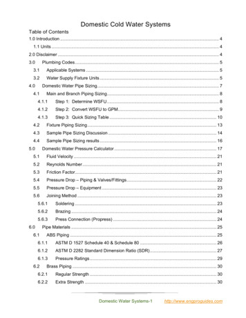
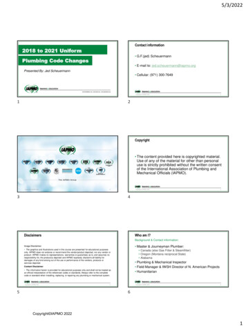
Notes to Table 2.6.3.2.A.(cont.):3) Bathroom group is based on a ½-inch size bathtubsupply pipe.A bathroom group is a defined term as “a group ofplumbing fixtures installed in the same room,consisting of one domestic-type lavatory, one watercloset and either one bathtub (with or without ashower) or one one-head shower.Division BPart 246
Notes to Table 2.6.3.2.A.(cont.):4) Add additional fixture to the fixture load forbathroom groupAdditional fixtures may be added to a bathroom group thatmeets the definition in 1.4.1.2.If any other fixtures, beyond those permitted incircumstances that comply with note (4) above, are fed fromthe piping that leads to a bathroom group, then the fixturesin the bathroom group must be considered individually fordetermining the fixture unit load.Division B Part 247
DWNot aBathroomGroupKSHoseBibbCWWCLavNot aBathroomGroupSHWCWCLavBTBTLavBathroom GroupHWTHose BTBibbLavWCKSCWDWBathroom Group48
2012 BCPC Table 2.6.3.2.A.Fixture or Device (1)(2)Dishwasher, commercial (5)Private use HydraulicLoad, FU’sMinSize ColdHotPublic use HydraulicLoad, FU’sTotal Cold Hot Total-------Dishwasher, domestic⅜”-1.41.4---Drinking fountain or water cooler⅜”---0.25-0.25Hose bibb½”2.5-2.52.5-2.5Hose bibb¾”3-36-6Hose bibb, combinations hot and cold½”1.91.92.51.91.92.5Lavatory, 8.3 LPM or less⅜”0.50.50.71.51.52Lavatory, greater than 8.3 LPM⅜”0.75 0.7511.51.52Sink, bar⅜”0.75 0.7511.51.52Sink, clinic service faucet½”---2.25 2.253Sink, clinic service with direct flush1”---6-6Sink, kitchen commercial, per faucet½”---334Division B Part 249
2012 BCPC Table 2.6.3.2.A.Fixture or Device (1)(2)Private use HydraulicLoad, FU’sMinSize ColdHotPublic use HydraulicLoad, FU’sTotal Cold Hot TotalSink, kitchen domestic, 8.3 LPM⅜”111.4111.4Sink, kitchen domestic, 8.3 LPM⅜”1.51.521.51.52Sink, laboratory⅜”---1.51.52Sink, laundry, 1 or 2 compartments⅜”111.4111.4Sink, service or mop basin½”---2.25 2.253Sink, washup, per faucet½”---1.51.52Shower head, 9.5 LPM or less per head½”111.4334Shower head, 9.5 LPM per head½”1.51.52334Shower, spray, multi-head, FU per head(5)111.4334Urinal, with direct flush valve¾”(6)-(6)(6)-(6)Urinal, with flush tank⅜”3-33-3Urinal, with self-closing metering valve½”2-24-4Division B Part 250
Notes to Table 2.6.3.2.A.(cont.):6) For fixture unit values for fixtures with direct flushvalves, see Sentence 2.6.3.2.(4) and Tables 2.6.3.2.Band 2.6.3.2.C.Division BPart 251
2012 BCPC Table 2.6.3.2.A.Fixture or Device (1)(2)Private use HydraulicLoad, FU’sMinSize ColdHotPublic use HydraulicLoad, FU’sTotal Cold Hot TotalWater closet, 6 LPF with flush tank⅜”2.2-2.22.2-2.2Water closet 6 LPF with flush tank⅜”3-35-5Water closet with direct flush valve1”(6)-(6)(6)-(6)Notes to Table 2.6.3.2.A.:(1)The fixture unit values in this Table are not applicable in certainassembly occupancies because of surges in use by the occupants. Forsuch occupancies, refer to specific design information(2)For fixtures not indicated in this Table, refer to Table 2.6.3.2.D.(3)Bathroom group is based on a ½-inch size bathtub supply pipe.(4)Add additional fixture to the fixture load for bathroom group.(5)Refer to manufacturer’s recommendations.(6)For fixture unit values for fixtures with direct flush valves, see Division BPart 2Sentence 2.6.3.2.(4) and Tables 2.6.3.2.B and 2.6.3.2.C.52
2.6.3.2. Hydraulic Load3) Where fixtures are supplied with both hot and coldwater, the hydraulic loads for maximum separatedemands shall be 75% of the hydraulic load of the fixtureunits given in Tables 2.6.3.2.A. and 2.6.3.2.D. when usinga detailed engineering design method.The 75% value can only be used in the detailed engineeringdesign method, of which the prescribed methods in theCode do not qualify.Division BPart 253
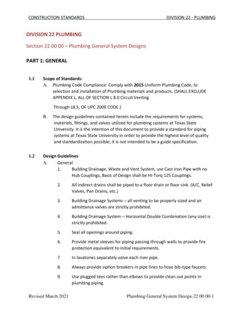
2.6.3.2. Hydraulic Load (cont.)4) The hydraulic load of urinals and water closets withdirect flush valves shall be the number of fixture unitslisted in Tables 2.6.3.2.B. and C. (See Appendix A.)Division BPart 254
Table 2.6.3.2.B.Sizing of Water Distribution systems for Urinals with direct Flush Valves2012 BCPC Table 2.6.3.2.BNumber of ValvesIndividual Fixture UnitAssigned in Decreasing ValuesFixture Units inAccumulative Values12020215353104548535 or more5 each58 5 each additionalNotes to Table 2.6.3.2.B:The accumulative fixture unit values are the total values to be used in conjunction withTable 2.6.3.2.A.Division BPart 255
Urinal Flush Valves#FUIncr.FUAccum.1234 420151085 ea2035455358 520354553Table A-2.6.3.B.5863¾”Ur5Ur5Ur8Ur10Ur15Ur20Flush Valve Urinals56
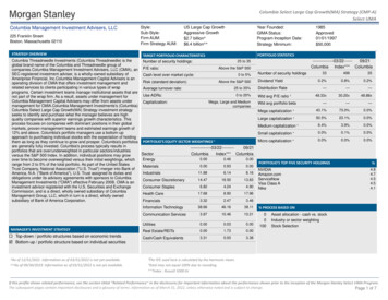
Table 2.6.3.2.C.Sizing of Water Distribution systems for Water Closets with direct Flush Valves2012 BCPC Table 2.6.3.2.CNumber of ValvesIndividual Fixture UnitAssigned in Decreasing ValuesFixture Units inAccumulative Values1404023070320904151055 or more10 for each public useand6 for each private use115 10 for each public useand111 6 for each private useNotes to Table 2.6.3.2.C:The accumulative fixture unit values are the total values to be used in conjunction withTable 2.6.3.2.A.57
WC Flush Valves#FUIncr.FUAccum.1234 44030201510 ea407090105115 10Table ater Closets Flush Valve58
Division BPart 259
3 FVWC’s6 Lavs8.3 L3 ) Sizing for Flush Valves60
2.6.3.4. Size2) Except as provided in Sentence (3), the size of a supplypipe that serves a fixture shall conform to Table 2.6.3.2.A.3) For fixtures listed in Table 2.6.3.2.A. that have apermitted supply pipe size of 3/8 inch, a connector notmore than 750 mm long and not less than 6.3 mm insidediameter may be used to supply water to the fixture.Division BPart 261
2.6.3.4. Size (cont.)(5) Where both hot and cold water is supplied to fixtures inresidential buildings containing one or two dwelling unitsor row houses with separate water service pipes, the watersystem may be sized in accordance with Table 2.6.3.4.where:Division BPart 262
2.6.3.4.(5) (cont.)a) the hydraulic loads for maximum separate demandson water distribution system piping are not less than 100%of the total hydraulic load of the fixture units givenin Tables 2.6.3.2.A, B, C or D for private use,b) the minimum water pressure at the entry tothe building is 200 kPa, andc) the total maximum length of water system is 90 m.Division BPart 263
Table 2.6.3.4.Water Pipe Sizing for Buildings Containing One or Two Dwelling Units or RowHouses with Separate Water Service PipesForming Part of Sentence 2.6.3.4.(5)1.5 m/s 5 ft/s2.4 m/s 8 ft/s3.0 m/s 10 ft/sSize ofWaterPipe,InchesWater Velocity, m/s3.02.41.5Hydraulic Load, fixture units½”874¾”1”21163191¼”4383571830Note to Table 2.6.3.4.:(1) Table 2.6.3.4. is not intended to limit water velocities that are specified in Sentence 2.6.3.5.(1).Division BPart 264
Notes to Table 2.6.3.4.:Table 2.6.3.4. is not intended to limit water velocities thatare permitted by Sentence 2.6.3.5.(1).Division BPart 265
2.6.3.5. Velocity1) The maximum permitted water velocities shall be thoserecommended by the pipe and fitting manufacturer.Division BPart 266
Section 2.7. Non-Potable Water Systems2.7.2.1. Markings Required(1) The location of non-potable water discharge and nonpotable water piping shall be identified by markings thatare permanent, distinct and easily recognized.Division BPart 267
A-2.7.3.2.(1) Outlets from Non-Potable Water SystemsThe location of outlets from non-potable water systemswhere they can be discharged into a sink or lavatory (i.e.bathroom sink), a fixture into which an outlet from apotable water system is discharged, or a fixture that is usedfor the preparation, handling or dispensing of food, drinkor products that are intended for human consumption,may have proven acceptable on the basis of pastperformance in some localities such as rest stops, and itsacceptance under this Code may be warranted.Division BAppendix68
A-2.7.3.2.(1) Outlets from Non-Potable Water Systems(cont.)Subclause 2.7.3.2.(1)(b) would permit non potable waterto be used to supply water closets or urinals provided thefixtures are not also connected to potable water.Division BAppendix69
2.7.4.1. Non-potable Water System Design(See Appendix A.)1) Non-potable water systems shall be designed, fabricatedand installed in accordance with good engineeringpractice, such as that described in the ASHRAE Handbooks,ASPE Handbooks and CAN/CSA-B128.1, “Design andInstallation of Non-Potable Water Systems.”Division BPart 270
A-2.7.4.1. Non-potable Water System DesignThere is a growing interest in Canada in using availablenon-potable water supplies in the place of potable ones forselected purposes such as flushing toilets and irrigatinglawns and gardens. Article 2.7.4.1. applies to non-potablewater systems regardless of the origin of the water. Thenon-potable water must meet applicable water qualitystandards as determined by an authority havingjurisdiction.Division BAppendix71
Good engineering practice would dictate that non-potablewater be of appropriate quality for the end use. TheCanadian Guidelines for Domestic Reclaimed Water for Usein Toilet and Urinal Flushing, as published by HealthCanada, provides appropriate water quality values forthose uses.Water quality values and monitoring requirements forreclaimed water are also prescribed by a regulation madeunder the Environmental Management Act (EMA).Reclaimed water is a subset of non-potable water,produced from larger volume systems accepting domesticor municipal wastewater.Division BAppendix72
Consequently, the monitoring requirements may be morestringent than necessary for smaller applications, but thewater quality values may still be taken in isolation and usedas a benchmark for non-potable water systems designed tomeet 2.7.4.1. to which the regulation under the EMA doesnot apply. The water quality values can includebiochemical oxygen demand (BOD5), turbidity (NTU) andfecal coliforms.Division BAppendix73
Note that the regulation under the EMA permits additionaluses for non-potable water under certain conditions. It isnot the intent of Section 2.7. to contradict the EMA or itsregulations, but rather, to regulate the end use of nonpotable water systems where the EMA does not apply.Division BAppendix74
Appendix A Explanatory MaterialThis Appendix is included for explanatory purposes onlyand does not form part of the requirements. Thenumbers that introduce each Appendix Note correspondto the applicable requirements in this Division. Thefigures are schematic only; they depict various parts ofthe plumbing system but do not include details. For anexplanation of the symbols and abbreviations used in thefigures, refer to the list provided at the end of the Code.Division BAppendix75
Division CPart 1 – GeneralPart 2 – Administrative ProvisionsAppendix A (Division C)76
2.2.1.2. Personnel Performing Plumbing Work1) Personnel performing installation, alteration or repair ona plumbing system shalla) possess a British Columbia tradesman's qualificationcertification as a plumber,b) be an indentured apprentice supervised by a journeymanpossessing a British Columbia tradesman's qualificationcertification as a plumber, orDivision CPart 277
2.2.2. PLUMBING DRAWINGS AND RELATED DOCUMENTS2.2.2.1. Information Required on Plumbing Drawings andRelated Documents1) If the authority having jurisdiction legally requires anapplication for a permit in respect of plumbing systems,plumbing drawings and related documents submitted withthe application for a plumbing permit shall showDivision CPart 278
2.2.2.1.(1) Information Required on Plumbing Drawingsand Related Documents (cont.)a) the location and size of every building drain and ofevery trap and cleanout fitting that is on a building drain,b) the size and location of every soil-or-wastepipe, trap and vent pipe, andc) a layout of the potable water distribution system,including pipe sizes and valves.Division CPart 279
2.3.1. ALTERNATIVE SOLUTIONS2.3.1.1. Application1) For the purposes of Clause 1.2.1.1.(1)(b) of Division A,on written request by the owner of a building or anauthorized agent of that owner, the authority havingjurisdiction shall accept a measure as an alternativesolution to an acceptable solution for the building ifsatisfied thatDivision CPart 280
2.3.1.1. Application (cont.)a) the measure will achieve at least the level ofperformance required by Clause 1.2.1.1.(1)(b) of Division A,andb) the acceptable solution does not expressly requireconformance to a provincial enactment other than theBritish Columbia Building Code.Division CPart 281
2.3.1.2.(2) Documentationb) information concerning any special maintenance oroperation requirements, including any plumbingsystem component commissioning requirements, that arenecessary for the alternative solution to achievecompliance with the Code after the plumbing system isinstalled.Division CPart 282
2.3.1.2. Documentation (cont.)6) Where more than one person is responsible forthe design of a plumbing system, a building or facility thatincludes a proposed alternative solution, the personrequesting the use of the alternative solution shall identifya single person to coordinate the preparation of thedesign, Code analysis and documentation referred to inthis Article.Division CPart 283
Part 10 – Energy and Water EfficiencySection 10.3 Water Efficiency10.3.1.2. Fixture Efficiency2012 Code did not carry forward the requirement sfor high efficiency flush water closets (4.8 lpf)under Article 10.3.1.2. introduced in October 2011.This was an oversight and will be addressed by anamendment shortly.84
10.3.1.2. Fixture Efficiency1) The flush cycle for the installation of a water closet orurinal must not exceed the flush cycle listed for thatfixture in Table 10.3.1.2.Table 10.3.1.2.Maximum Flush CycleForming part of Sentence 10.3.1.2.(1)FixtureLitresWater Closet (Tank Type)6.0Water Closet (Direct Flush)6.0Urinal (Tank Type)5.7Urinal (Direct Flush)5.785
10.3.1.2. Fixture Efficiency2) The flush cycle for the installation of a water closet orurinal in buildings classified as group C must not exceedthe flush cycle listed for that fixture in Table 10.3.1.2.(2).Table 10.3.1.2.Maximum Flush CycleForming part of Sentence 10.3.1.2.(2)FixtureWater Closet (Tank Type)Litres4.8(1)Water Closet (Direct Flush)6.0Urinal (Tank Type)5.7Urinal (Direct Flush)5.7Notes to Table 10.3.1.2.(1) A water closet which provides a dual flush cycle option of both 4.1 Lor less and 6.0 L shall be deemed to comply.86
IndexSymbols and Abbreviations – Table AddedConversion Factors - Expanded87
AL-PEX) Composite Pressure-Pipe Systems," in hot water systems. Division B Part 2 12. 2.2.10.6. Supply and Waste Fittings 1) Supply fittings shall conform to . "ASPE Plumbing Engineering Design Handbook," chapter on Cold Water Systems, and d)ASPE 2005, "ASPE Plumbing Engineering Design Handbook," chapter on Domestic .