Transcription
Diode Reverse Recovery and its Effect onSwitching LossesPeter Haaf, Senior Field Applications EngineerJon Harper, Market Development ManagerNovember 2006www.fairchildsemi.com
Agenda1.2.3.4.5.6.BasicsMathematical EstimationsComparison of the Estimations with real measurementsSwitching Losses vs. VoltageSwitching Losses vs. CurrentEON Losses during Hard Switching with different DiodeTechnologies7. Effect of parallel Caps on Switching Losses8. Switching Losses vs. rise and fall time9. Summary2
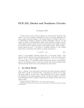
Diode charge distribution in conductingand non-conducting statesMinority carrier concentrationnear the junctionHoleconcentrationin N-type regionElectronconcentrationin P-type regionElectronconcentrationin P-type regionxx 0P-typeMinority carrier concentrationnear the junctionHoleconcentrationin N-type regionxx 0N-typeP-typeN-typeDiode blockingDiode conducting3
Diode Forced Commutation BehaviorStep 1: Switch is turned onCurrent risesDC BusIL2VDD1SwitchReference GNDStep 2: Switch is turned offCurrent is circulatingIDIODEVDIODE 3 VSWITCH-Step 3: Switch is turned onagain, Diode isrecovering andcurrent continuesrisingISWITCH4
Switching loss calculations Definition ofPower LossesP 1/T* V(t) * I(t) dt mean (V(t) * I(t))IVE P*t V(t) * I(t) dt area (V(t) * I(t))Pon EON * f ;Poff EOFF * ftE (1/3)*V*I*tE (1/2)*V*I*ttt5E (1/6)*V*I*tt
Turn On Loss Due to Diode Recovery (Phase tR)VCEIRRMICIL assumed constant during switching timedIC/dtEon1tAdIF/dttBwithEon1VFVout * I L * t R2dI/dt IL / tRtFIF Vout * I L22 * dI/dtIRRMswitching time: tR tA tBtRot t0 IGBT turns ont0t1t2t3VRM6
Turn On Loss Due to Diode Recovery (Phase tA)VCEIL assumed constant during switching timeIRRMIC IE on2 Vout * I L RRM * t A2 dIC/dttAdIF/dtwithtBtFdt I2 E on2 Vout* I L* RRM IRRM *2 2 *dI IFVFIRRMtRt t0 IGBT turns ont0t1t2I RRMdI/dt tAt3VRM7switching time:tR tA tB
Turn On Loss Due to Diode Recovery (Phase tB)VCEIRRMICIL assumed constant during switching timedIC/dtE on3tF tBtAdIF/dt II Vout * L RRM * t B3 2tBtFswitching time:tR tA tBIFVFIRRMtRAt t to IGBT turns ont0t1t2Diodelosst3VRM8Vout * I RRM * t B 6
Double check of the formulas:Eon calculation vs. measurementVCEEONIc 4 AEon 32.67 uJPon 1.63 WEon1 Eon2 Eon3 11.20 uJ14.00 uJ7.47 uJPon Pon Pon 0.56 W0.70 W0.37 WDiode:Eoff 9.33E-01 uJPoff 0.05 W950 (kHz)4 (A)280.00 (V)2.00E 08 (A/s)2 (A)1.00E-08 (s)FrequencyCurrentUdcdI/dtIrr; Diodetf fall time
8A Stealth II versus Stealth comparisonLoss calculation 25 C and 125 CFFP08S60SISL9R860P2SpecificationTC 25ºCTC 125ºCTC 25ºCTC 125ºCtA / ns (typ)11.925.216.415.1tB / ns (typ)7.132.860.637.9IRRM / A (typ)2.24.33.46.5QRR / nC (typ)211251501901182322462202.11.62.01.6Switch lossesexample calculation / µJVF / V (typical)Measured with di/dt 200A/us, see datasheets for full detailsExample: Loss in switch for 8A, di/dt 200A/us, VDD 390VEquations in Power Seminar 2007 documentation10
8A Stealth II versus Stealth comparisonLoss calculation 75 C and 100 CFFP08S60SISL9R860P2SpecificationTC 75ºCTC 100ºCTC 75ºCTC 100ºCtA / ns (typ)18.521.915.815.5tB / ns (typ)2026.449.243,5IRRM / A (typ)3.33.85.05.7172201235228VF / V (typical)1.851.7251.81.7Switching loss @ 100 kHz / W17.220.123.522.8Switch lossesexample calculation / µJCalculated with di/dt 200A/us, see datasheets for full detailsExample: Loss in switch for 8A, di/dt 200A/us, VDD 390VEquations in Power Seminar 2007 documentationLinear approximation: of ta, tb, Irrm and Vf6.3 W difference on switching losses11
8A Stealth II versus Stealth comparisonLoss A/divVdiode:100V/divId:2A/divEon : 106.2uJEon : ETTdiodedTMOSFET 7092.650.999Test co nditio n : Vin 2 2 0 Vac , Po ut 4 0 0 V/ 1 A( 4 0 0 W) , Fs 1 0 0 kHz125.2 W difference in input power
Test circuitsIdsIdsVdsVdsTest Circuits which are used for the following measurements13
Waveforms and loss definitionSwitch off lossesSwitch on lossestd off: 90 % Vge 90 % Icetf: 90 % Ice 10 % Icetd on: 10 % Vge 10 % Icetr: 10 % Ice 90 % Ice14
Switching Losses vs. VoltageFQP9N50C ISL9R460EONEON / EOFFlossesVIN 100VEON 8.7uJEOFF 9.5uJVIN 300VEON 32.3uJEOFF 23.1uJ15EOFF
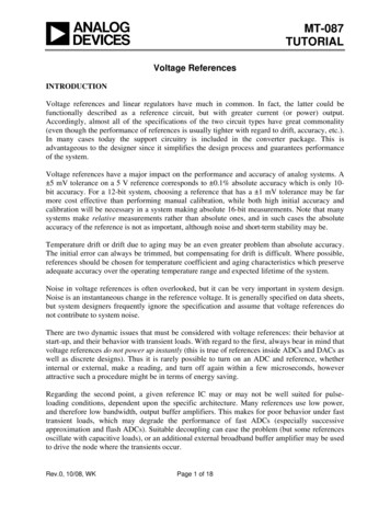
Switching Losses vs. Voltage: EON and EOFF lossesEon and Eoff losses of the FET - FQP9N50C vs. Input Voltage50Comparison oftwo Stealth diodes,which are optimized forhard switching4540Eon and Eoff Losses [uJ]35Eon @ ISL9R156030Eoff @ ISL9R156025Eon @ ISL9R460Eoff @ ISL9R46020151050050100150200250300350Input Voltage [V]Higher Current rating of the Diode will increaseEon, but decrease Eoff (Diode capacitance acts asa snubber). Eon is dominating!16FQP9N50C
Switching Losses vs. CurrentFQP9N50C ISL9R460 @ VIN 300VI 2A, EON 16.7uJI 4A, EON 33.4uJI 6A, EON 54.8uJI 2A, EOFF 9.7uJI 4A, EOFF 24.1uJI 6A, EOFF 43.1uJ(nearly) Linear relation between current and losses.17
EON f (Ice) and EOFF f (Ice) for different diodetechnologies and ratingsEon and Eoff losses of the FET - FQP9N50C vs. Current200Eon and Eoff Losses [uJ]180160Eon @FCP11N60FEon @ FQPF5N50CFEon @ RURD660Eon @ RHRP860Eon @ ISL9R460Eoff @ ISL9R4601401201008060402000123456Current [A]Technologies as well as rating will have a bigimpact on the Eon losses. Fast recovery FETs willlead to significant higher Eon losses compared tosingle diode technologies. Sometimes thereason for external fast recovery diodes.187FQP9N50C
Variation of IRRM with load current for different diodetechnologiesIrr, Reverse Recovery Peak Current of the Diode vs. CurrentR e v e rs e R e c o v e ry C u rre n t [A ]1412Irr @ FCP11N60FIrr @ FQPF5N50CFIrr @ RURD660Irr @ RHRP860Irr @ ISL9R460108FQP9N50C64200123456Current [A]Irr values are a good indicator for a loss comparisonof diodes.Only Irr’s measured at the same dI/dt are comparable!197
EON Losses at Hard Switching with differentDiode Technology @ VIN 300V @ I 4AMUR1560; EON 77.7uJRURD660; EON 60.1uJRHRP860; EON 37.9uJISL9R1560; EON 42.9uJISL9R860; EON 33.1uJISL9R460; EON 32.3uJ20
Variation of the EON Losses with input voltage fordifferent diode technologies and ratingsEon losses of the FET - FQP9N50C vs. Input Voltage9080Eon Losses [uJ]70605040Eon @ MUR1560Eon @ RURP860Eon @ RURD660Eon @ FFPF10UP60Eon @ ISL9R1560Eon @ RHRP860Eon @ ISL9R860Eon @ ISL9R460Eon @ SIC 6A3020100050100150200250300350Input Voltage [V]Especially in hard switching applications the diodetechnology will have a significant impact on the Eonlosses of the switch.21FQP9N50C
Variation of IRRM with input voltage for different diodetechnologiesIrr, Reverse Recovery Peak Current of the Diode vs. Input VoltageIrr @ MUR1560Irr @ RURD660Irr @ FFPF10UP60Irr @ ISL9R1560Irr @ RHRP860Irr @ ISL9R860Irr @ ISL9R460Irr @ SIC 6AReverse Recovery Current Irr[A]76543210050100150200250300350Input Voltage [V]The Irr value is a good parameter to estimate theswitching losses of different technologies.Only Irr’s measured at the same dI/dt are comparable!22FQP9N50C
Effect of temperature on reverse recoverydI/dt 200A/ms, Vdd 400V, If 8A, Tj 25 C and Tj 125 CTwo industry standard diodesResults for Tj 25 CResults for Tj 125 CSmall differenceBig differenceThe difference between low and high temperature reverse recoverybehavior is not the same for all technologies. Be careful if you compareonly at low temperatures.23
Switching Losses @ increasing switching speed Switching off:Same FET and Diode, reducing Rg:EOFF 22.8uJ Ù 16.7uJDrawback: ringing due to parasitic Ind. & CapsAll measurements: FDD6N50 ISL9R460, U 300V, I 4ARecommended RgLow RgGood switching performance, no ringingBad switching performance, ringing, but lower EOFF24
Switching Losses @ increasing switching speed- Same MOSFET, different Rg Diode ISL9R460, U 300V, I 4AFDD6N50, Rg 10 OhmEON 8 uJdI/dt 1400A/usIRRM 6.2ARight : FDD6N50, Rg 3 OhmEON 4 uJdI/dt 1600A/usIRRM 7.4A25
Switching Losses @ increasing switching speed- Different MOSFET Technologies Diode ISL9R460, U 300V, I 4AFQP9N50C, Rg 30 OhmEON 23.2 uJdI/dt 400 A/usIRRM 2.6 AFDD6N50, Rg 30 OhmEON 15.3 uJdI/dt 640 A/usIRRM 3.9 A26
Variation of IRRM with dI/dt for different diodetechnologiesReverse Recovery Current Irr of the Diode vs. dI/dt @ V 300V @ I 4A109Reverse Recovery Current Irr [A]876Irr @ FFP08H60SIrr @ ISL9R860Irr @ ISL9R46054321002004006008001000120014001600dI/dt [A/us]A higher dI/dt will increase the reverse recovery current, but 27
Variation of EON losses with di/dt for different diodetechnologiesEon losses of the FET vs. dI/dt @ V 300V @ dI/dt 4A3530Eon Losses [uJ]2520Eon @ FFP08H60SEon @ ISL9R860Eon @ ISL9R460151050020040060080010001200dI/dt [A/us]A higher dI/dt will decrease the Eon losses.2814001600
Effect of parallel caps on switching losses@ VIN 300V @ I 4A Diode ISL9R460EON 32 uJNo parallel CapacitanceEOFF 27 uJEON 39 uJCpar 470pFEOFF 7.8 uJ¾ Increase of the Eon losses due to the parallel Capacitance.¾ Advantages in switching off¾ Overall losses? 29EON 57 uJCpar 1nFEOFF 5.47 uJ
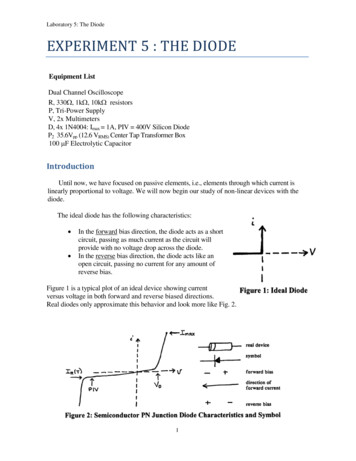
Effect of parallel caps on switching lossesEon and Eoff losses with a snubber Capacitance100A small capacitance can help to reduce the overall switching lossesE to t / E o n / E o ff lo s s e s [u J ]90Etot at 300V80Etot at 200VEtot at 100VEoff at 300V7060Eon at 300VEoff at 200VEon at 200V5040Eoff at 100V30Eon at 100V20100010080 pF @ 300 V200300400500600700800900Capacitance parallel to the Diode [pF]200 pF @ 200 V450 pF @ 100 VAs higher the voltage, as smaller the cap to decreasethe overall losses.301000
Summary¾ Reverse recovery in diodes in half-bridge structures causes small losses in the diodeslarger losses in the MOSFET/IGBT¾ IRRM and tRR increase with temperature di/dt current (less dominant)¾ Larger current rated diodes of the same family have higher IRRM resulting in higher EON (measured at the same dI/dt for comparison) have larger capacitance, resulting in lower EOFF cause higher total switching losses¾ Higher di/dt results in lower EON losses, but also in a higher IRRM¾ Addition of extra capacitance increases EON losses but decreases EOFF losses addition of extra capacitance could reduce total losses.31
Jon Harper, Market Development Manager November 2006. 2 Agenda 1. Basics 2. Mathematical Estimations 3. Comparison of the Estimations with real measurements 4. Switching Losses vs. Voltage . Irr, Reverse Recovery Peak Current of the Diode vs. Current 0 2 4 6 8 10 12 14 01 23 45 67 Current [A] Reverse Recovery Current [A] Irr @ FCP11N60F Irr .