Transcription
ECE 255, Diodes and Nonlinear Circuits18 January 2018In this lecture, the use of the pn junction as a diode will be discussed. Thediode is one of the simplest semiconductor device, and finds applications inmany modern electronic gadgets. The marked feature of a diode is that its IV relationship is nonlinear, making its analysis challenging. However, we willexploit as much of our knowledge in linear circuit analysis to analyze circuitswith nonlinear diodes in them. It has been shown that as the voltage increases,the current cannot be linearly related to the applied voltage. This is unlike aresistor where one has V IR where V is linearly related to I. For a diodemade from a pn junction, this relation, as shown previously, is V I IS e VT 1(0.1)where V is the applied of biasing voltage and I is the diode current. Thisphysical model is derived from semiconductor physics. It has the property thatwhen V VT , I tends to infinity. But when V VT , I IS which isvery small. Here, IS is varyingly called the saturation current, the generationcurrent, the leakage current, or the scale current; the last name follows fromthat this current scales as the cross-sectional area of the diode.1An Ideal DiodeThe i-v relation1 of an ideal diode is such that the current becomes infinitelylarge when it is on, or in forward bias. Conversely, the current is zero whenthe diode is off, or in reverse bias. This idealization can be used to simplifythe analysis of some simple nonlinear circuits. As shown in Figure 1, the use ofsuch idealization turns a nonlinear circuit into set of linear circuits that can beanalyze easily.Printed on March 14, 2018 at 10 : 21: W.C. Chew and S.K. Gupta.the text book, the lower cases will be used for total current and total voltagein this lecture.1 Following1
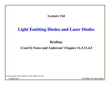
Figure 1: (a) The symbol of the diode. (b) The i-v characteristic of a pn junctionas an ideal diode. (c) When the diode is reverse biased, it is an open circuit oroff. (b) When the diode is forward biased, it is a short circuit or on (Courtesyof Sedra and Smith).Figure 2 shows the use of an ideal diode, where the on-off states are replacedwith open and short circuits respectively. Then the circuit can be analyzedsimply as such according to the state of the diode using linear circuit analysis.The behavior of the circuit can also be easily understood.2
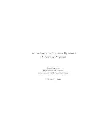
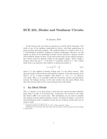
Figure 2: (a) The model of diode circuit. (b) The input voltage signal whichis an AC signal. (c) The circuit model when the diode is on. (d) The circuitmodel when the diode is off. (e) The output voltage (Courtesy of Sedra andSmith).The turning on of an ideal diode can be delayed by biasing it with the DCvoltage source as shown in Figure 3. This also resembles the charging of a 12 Vbattery by an AC source whose peak voltage is 24 V.Example 1.2For an ideal diode, it only has two states, the on or the off state. Onewill analyze the circuit by assuming that the diodes are either on or off, andanalyze the voltage and current across the diodes accordingly using linear circuitanalysis. In the on state, the voltage drop across the diode is zero, while in theoff state, the current flow through the diode is zero. If the answer contradicts theassumption, it implies that the assumption is wrong, and it has to be revised.For example in Figure 4(a), one assumes that both diodes are on. Then the2 Example4.1 of textbook.3
Figure 3: A DC voltage source can be used to delay the turning on of the idealdiode (Courtesy of Sedra and Smith).voltage at node B is zero andID2 10 0 1 mA10(1.1)Writing KCL (Kirchhoff Current Law) at node B, thenI 1 0 ( 10)5(1.2)giving I 1 mA. Hence, both diodes are on, and not contradicting the assumption.Figure 4: The circuit diagram for analyzing nonlinear circuits with ideal diodesfor Example 1 (Courtesy of Sedra and Smith).For the case in Figure 4(b), one first assumes that both diodes are on. Then4
VB 0 and V 0, andID2 10 0 2 mA5(1.3)0 ( 10)10(1.4)Applying KCL at node B,I 2 giving I 1 mA. This contradicts our assumption that the diode D1 is on.To revise the wrong assumption, one assumes that D1 is off while D2 is on.Then the current through D2 isID2 10 ( 10) 1.33 mA15(1.5)The voltage at node B is obtained by applying KVL (Kichhoff voltage law) thenVB 10 10 1.33 3.3 V(1.6)Hence, VB 0 implying that D1 is off or reverse biased giving rise to I 0 andV 3.3 V.2More on I-V Characteristic of Junction DiodesThe i-v relation of a diode, as shown by using device physics, is given by vi IS e VT 1(2.1)where VT kB T /q is about 25 mV at room temperature. When the voltage v isabout 0.1 V, it is about 4 times VT . And ev/VT is about e4 54.6 which is quitelarge. When v 0.6 V, a biasing voltage 6 times larger, then e4 6 e24 2.65 1010 which is a very large number. A small increase in v can overcome thesmallness of IS which can be of the order of 10 15 . Hence, the turn-on voltageof a diode is roughly 0.6-0.8 V. The above equation (2.1) can be inverted to give iv VT ln 1(2.2)ISWhen the bias voltage v is large, the i-v relation (2.1) can be simplified andapproximated with the exponential model asvi IS e VT(2.3)Since IS is proportional to n2i , and that ni T 3/2 e Eg /(2kB T ) , one deduces thati T 3 e Eg /(kB T ) ev/VT T 3 e (Eg /q)/VT ev/VT(2.4)For silicon, Eg /q 1.1 V. Defining Vg Eg /q, the above becomesi CT 3 e (Vg v)/VT5(2.5)
Taking the natural log of the above, one arrives atv vg VT ln i VT ln(CT 3 )(2.6)Since v 0.7 V, then v vg , the above implies that ln(CT 3 ) ln i, or that vbecomes smaller as T increases.Revision of previous knowledge–The formula for the saturation current is DpDnIS Aqn2i (2.7)Lp NDLn NAwhich is of the order of 10 15 A. As have been learned earlier, the formula forni isni BT 3/2 e Eg /(2kB T )(2.8)B 7.3 1015 K 3/2 cm 3(2.9)whereHence, when the temperature T increases, there are more thermalized carriersni giving rise to larger IS . It is generally assume that IS doubles for every 5 C rise in temperature.2.1Temperature Dependence of the I-V CharacteristicFigure 5: The temperature dependence of the i-v characteristic of a diode (Courtesy of Sedra and Smith).As shown in (?), for a fixed i, the voltage v is linearly proportional to VT whichis again linearly proportional to T . Hence v increases as T increases, giving6
rise to the temperature dependence as shown in Figure 5. In the above, IS istemperature dependent as well, but its temperature dependence is mitigated bythe ln function.3More on Diode ModelingFigure 6: The case of a diode connected to a battery source via a load resistor(Courtesy of Sedra and Smith).Assuming that the diode is connected to a resistor as shown in Figure 6, andone needs to find the diode current ID and voltage VD . Since the i-v relation ofa diode is nonlinear, there is no simple way to solve this problem. The solutionhas to be sought graphically or numerically.3.1The Exponential ModelLet us assume that the bias voltage is large so that the I-V relationship for a pnjunction diode can be approximated with high accuracy with the exponentialmodel to beID IS eVD /VT(3.1)The other equation for I-V is governed by KVL for the voltage drop acrossthe resistor R, or thatVRVDD VDID (3.2)RRThe two unknowns to be sought are ID and VD , assuming the rest to be knownconstants. Here, ID and VD are common to both equations. The above constitute two simultaneous equations for two unknowns.Albeit simple, these equations have no closed form. For instance, one caneliminate VD by inverting the first equation, and substituting into the secondequation, one getsVDD VT ln(ID /IS )ID (3.3)RThe above equation has one unknown ID , but it is a transcendental or nonlinearequation that cannot be solved in closed form.7
3.1.1Graphical AnalysisOne way to solve nonlinear equation is via graphical method, as shown in Figure7. One plot in the graph is for equation (3.1) representing the diode characteristic using the exponential model. The second plot, called the load line, isfrom equation (3.2) due to the resistive load of the circuit.The solution is given by the point where the plots for the two equationsmeet. At this point, both equations share the same ID and VD , and is calledthe operating point or the Q point. This is a method of finding the solution oftwo simultaneous equations, one of which can be nonlinear. When the numberof equations is large, this method is unwieldy, and one resorts to a numericalmethod of solving these equations.Figure 7: The graphical solution yields the solution of a transcendental equationquickly by visual inspection. (Courtesy of Sedra and Smith).8
3.1.2Iterative Analysis—Method of Successive ApproximationsFigure 8: Iterative method such as the method of successive approximation canbe converted into a computer program easily (Courtesy of Sedra and Smith).The graphical method can be used by humans easily because of our gifted visualintelligence. However, it is difficult to program a computer to pick out the operating point or the Q point on a graph. For numerical or computer method, itis better to design an algorithm that can be converted to a program systematically: such is the spirit of iteration analysis or method. We will illustrate thiswith the method of successive approximation in the following example,which can be converted into a computer program easily.Example 2.3In this method, first, we guess a VD which is not correct, unless we haveclairvoyance. Say, one starts with VD 0.7 V, and we can find out where onthe load line the current should be if it were to satisfy (3.2). To this end, thecorrespond current through the resistor is given byID VDD VD5 0.7 0.43 mAR1(3.4)Next, given this new ID , one needs to ascertain what VD should be from thediode equation. One can invert equation (3.1) to obtain VD , given ID . However,we do not know IS , but it can be found since it is given, in this example, thatID 1 mA when VD is 0.7 V. Alternatively, one can use the fact thatI1 IS eV1 /VT ,3 ThisI2 IS eV2 /VTis Example 4.2 of the textbook.9(3.5)
thenI2 e(V2 V1 )/VTI1(3.6)Inverting the above givesV2 V1 VT lnI2,I1V2 V1 2.3VT log10I2I1(3.7)Using the above, and using that 2.3VT 60 mV, with V1 0.7 V, I1 1mA, and I2 4.3 mA, gives V2 0.738 V. This process can be repeated untilthe solution converges. When convergence is reached, the solution changes littlewith iteration number.The method of successive approximation is also shown in Figure 8. A wordof caution is that this method does not always converge. Then other iterativeor numerical methods have to be used, for instance, the secant method, or theNewton-Raphson method.4The Constant-Voltage-Drop ModelAs can be seen previously, when nonlinear equations are involved, their solutionsare often difficult. One method is to approximate the I-V characteristics of adiode with piecewise linear approximation. When the diode is operating in thepiecewise linear regime, simpler linear methods can be applied. The constantvoltage-drop model is such an attempt to simplify the analysis. The gist of thismethod is shown in Figure 9. When the diode is off, or the bias voltage is below0.7 V, then it is replaced by an open circuit. When the diode is on, it is replacedby a short circuit with an internal battery with voltage of vD as shown.10
Figure 9: The constant-voltage-drop model can be use to simplify the analysisof diode circuits (Courtesy of Sedra and Smith).5Small-Signal ModelAnother way of making a linear approximation to a nonlinear equation is to usethe small signal model. The schematic for this model is shown in Figure 10.Figure 10: The circuit for a small signal model where a small voltage VDD issuperposed on top of a large voltage VDD (Courtesy of Sedra and Smith).11
Figure 11: Graphical depiction of the small signal model where vd (t) is assumedto be much smaller than VD (Courtesy of Sedra and Smith).The Math Behind Small Signal ModelIn this model, one assumes that the voltage across the diodevD (t) VD vd (t)(5.1)where vd (t) is a small signal voltage compared to VD , the quiescent DC voltage.The corresponding current through the diode is theniD (t) IS evD (t)/VT IS e(VD vd (t))/VT(5.2)The above can be rewritten asiD (t) IS eVD /VT evd (t)/VT ID evd (t)/VT12(5.3)
where ID is time independent, and isID IS eVD /VT(5.4)Since vd (t)/VT 1 always, using ex 1 x when x is small, the above equation(5.3) can be approximated, namely, vd (t)IDiD (t) ID 1 ID vd (t)(5.5)VTVTWritingiD (t) ID id (t)(5.6)where id (t) is a small signal current, or that id (t) ID , thenid (t) IDvd (t)VT(5.7)One can then define an incremental resistance, or small-signal resistancerd VTID(5.8)The above approximation converts a nonlinear problem into a linear problem atthe DC bias point, the quiescent point, or the Q point. The slope of the i-vcurve at this point is also inversely proportional to the incremental resistance,namely that iD1 (5.9) vD iD IDrdFigure 12: A nonlinear diode circuit can be replaced by a linear resistor circuitunder the small signal approximation (Courtesy of Sedra and Smith).The small-signal approximation is mathematically equivalent to Taylor series approximation. By so doing, a nonlinear function is replaced with a linearfunction around the Q point. This is also called the linearization approximation.13
Figure 13: Figure for Example 4.5 of textbook illustrating the use of small-signalmodel to solve a nonlinear diode problem (Courtesy of Sedra and Smith).Example 3.4Consider a circuit shown in Figure 13 with R 10 kΩ. The power sourceV has a DC value of 10 V, on top of which is superposed an AC signal with1-V peak amplitude at 60 Hz. This models the imperfection of the power supplyripple. Find the DC voltage of the diode, and the sinusoidal signal across it,assuming that VD of the diode is 0.7 V at then ID 1 mA.Answer:Assuming DC signal only, and that VD 0.7 V, as shown in Figure 13(b),then10 0.7ID 0 0.93 mA(5.10)1Since we are in the small-signal regime, then the incremental resistance is givenbyVT25rd 26.9 Ω(5.11) ID0.93The original circuit can now be replaced by the small signal model of Figure13(c). Using the voltage divider rule, thenvd (t) vs (t)rdR rd(5.12)The peak voltage is thenvd (peak) vs (peak)rd0.0269 1 2.68 mVR rd10 0.0269(5.13)This voltage is small compared to VT affirming out small-signal assumption.4 Sameas Example 4.5 of the textbook.14
o . (b) When the diode is forward biased, it is a short circuit or on (Courtesy of Sedra and Smith). Figure 2 shows the use of an ideal diode, where the on-o states are replaced with open and short circuits respectively. Then the circuit can be analyzed simply as such according to the state of the diode using linear circuit analysis.