Transcription
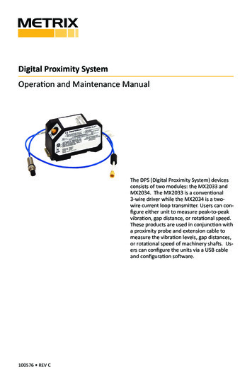
Digital Proximity SystemOperation and Maintenance ManualThe DPS (Digital Proximity System) devicesconsists of two modules: the MX2033 andMX2034. The MX2033 is a conventional3-wire driver while the MX2034 is a twowire current loop transmitter. Users can configure either unit to measure peak-to-peakvibration, gap distance, or rotational speed.These products are used in conjunction witha proximity probe and extension cable tomeasure the vibration levels, gap distances,or rotational speed of machinery shafts. Users can configure the units via a USB cableand configuration software.100576 REV C
TABLE OF CONTENTS1. General Information. . . . . . . . . . . . . . . . . . . . . . . . . . . . . . . . . . . . . . . . . . . . . . . . . . . . . . . . 31.1 Safety Terms and Symbols . . . . . . . . . . . . . . . . . . . . . . . . . . . . . . . . . . . . . . . . . . . . . . . . . . 31.2 General Safety Summary. . . . . . . . . . . . . . . . . . . . . . . . . . . . . . . . . . . . . . . . . . . . . . . . . . . .32. Overview. . . . . . . . . . . . . . . . . . . . . . . . . . . . . . . . . . . . . . . . . . . . . . . . . . . . . . . . . . . . . . . . . . . . . . . . . . 42.1 MX2033 Three-Wire Proximity Driver. . . . . . . . . . . . . . . . . . . . . . . . . . . . . . . . . . . . . . . . . . . . . . . 52.2 MX2034 Two-Wire Transmitter. . . . . . . . . . . . . . . . . . . . . . . . . . . . . . . . . . . . . . . . . . . . . . . . . . . . . 52.3 For more information. . . . . . . . . . . . . . . . . . . . . . . . . . . . . . . . . . . . . . . . . . . . . . . . . . . . . . . . . . . . . 53. Configuring a DPS. . . . . . . . . . . . . . . . . . . . . . . . . . . . . . . . . . . . . . . . . . . . . . . . . . . . . . . . . . . . . . . . . . 63.1 Equipment Required. . . . . . . . . . . . . . . . . . . . . . . . . . . . . . . . . . . . . . . . . . . . . . . . . . . . . . . 63.2 Software Installation. . . . . . . . . . . . . . . . . . . . . . . . . . . . . . . . . . . . . . . . . . . . . . . . . . . . . . . 73.3 Connecting the DPS to a Computer. . . . . . . . . . . . . . . . . . . . . . . . . . . . . . . . . . . . . . . . . . 113.3.1 Remove the Base. . . . . . . . . . . . . . . . . . . . . . . . . . . . . . . . . . . . . . . . . . . . . . . . . . . . . . . 113.3.2 Apply Power. . . . . . . . . . . . . . . . . . . . . . . . . . . . . . . . . . . . . . . . . . . . . . . . . . . . . . . . . . . 123.4 Launching the DPS Configuration Software. . . . . . . . . . . . . . . . . . . . . . . . . . . . . . . . . . . . 123.5 Main Screen. . . . . . . . . . . . . . . . . . . . . . . . . . . . . . . . . . . . . . . . . . . . . . . . . . . . . . . . . . . . . 133.5.1 Command Line Options. . . . . . . . . . . . . . . . . . . . . . . . . . . . . . . . . . . . . . . . . . . . . . . . . . 133.5.2 Device Information. . . . . . . . . . . . . . . . . . . . . . . . . . . . . . . . . . . . . . . . . . . . . . . . . . . . . . 133.5.3 Device Communication Status. . . . . . . . . . . . . . . . . . . . . . . . . . . . . . . . . . . . . . . . . . . . . 143.5.4 Configurable Device Settings. . . . . . . . . . . . . . . . . . . . . . . . . . . . . . . . . . . . . . . . . . . . . . 143.5.5 Confirming the Configuration. . . . . . . . . . . . . . . . . . . . . . . . . . . . . . . . . . . . . . . . . . . . . 163.5.6 Printing a Label. . . . . . . . . . . . . . . . . . . . . . . . . . . . . . . . . . . . . . . . . . . . . . . . . . . . . . . . . 163.5.7 Installing the Label. . . . . . . . . . . . . . . . . . . . . . . . . . . . . . . . . . . . . . . . . . . . . . . . . . . . . . 183.6 Using the MX2034 Buffered Output . . . . . . . . . . . . . . . . . . . . . . . . . . . . . . . . . . . . . . . . . 184. Verification and Calibration. . . . . . . . . . . . . . . . . . . . . . . . . . . . . . . . . . . . . . . . . . . . . . . . . 194.1 Scale Factor Verification. . . . . . . . . . . . . . . . . . . . . . . . . . . . . . . . . . . . . . . . . . . . . . . . . . . 204.2 Scale Factor Custom Calibration. . . . . . . . . . . . . . . . . . . . . . . . . . . . . . . . . . . . . . . . . . . . . 244.2.1 Current Loop Verification (MX2034 only). . . . . . . . . . . . . . . . . . . . . . . . . . . . . . . . . . . . 265. Troubleshooting . . . . . . . . . . . . . . . . . . . . . . . . . . . . . . . . . . . . . . . . . . . . . . . . . . . . . . . . . . 295.1 MX2033 and MX2034. . . . . . . . . . . . . . . . . . . . . . . . . . . . . . . . . . . . . . . . . . . . . . . . . . . . . 295.2 MX2034 Only. . . . . . . . . . . . . . . . . . . . . . . . . . . . . . . . . . . . . . . . . . . . . . . . . . . . . . . . . . . . 306. Performance Graphs. . . . . . . . . . . . . . . . . . . . . . . . . . . . . . . . . . . . . . . . . . . . . . . . . . . . . . . 316.1 Driver/Transmitter Temperature Response. . . . . . . . . . . . . . . . . . . . . . . . . . . . . . . . . . . . 316.1.1 MX2030/BN 3300 5 Meter System. . . . . . . . . . . . . . . . . . . . . . . . . . . . . . . . . . . . . . . . . 316.1.2 MX2030/BN 3300 9 Meter System. . . . . . . . . . . . . . . . . . . . . . . . . . . . . . . . . . . . . . . . . 346.1.3 Metrix/BN 7200 5 Meter System . . . . . . . . . . . . . . . . . . . . . . . . . . . . . . . . . . . . . . . . . . 366.1.4 Metrix/BN 7200 9 Meter System . . . . . . . . . . . . . . . . . . . . . . . . . . . . . . . . . . . . . . . . . . 396.2 Phase Delay. . . . . . . . . . . . . . . . . . . . . . . . . . . . . . . . . . . . . . . . . . . . . . . . . . . . . . . . . . . . . 427. Trademarks and Copyrights. . . . . . . . . . . . . . . . . . . . . . . . . . . . . . . . . . . . . . . . . . . . . . . . . 43Doc# 100576 REV C (Sept 2017) Page 2 of 42
1. GENERAL INFORMATION1.1 SAFETY TERMS AND SYMBOLSTerms that appear in this manual requiring special attention include: WARNING: Warning statements identify conditions or practices that could result in injuryor loss of life. CAUTION: Caution statements identify conditions or practices that could result in damage to the product, loss or corruption of data, or damage to the environment or otherproperty. NOTE: Notes identify material of special interest or importance to the user, not includingcautions or warnings.Symbols that may appear on the product and/or in this manual include:HIGH VOLTAGEPRESENTPROTECTIVEEARTHDANGER orCAUTIONFUNCTIONALGROUNDNOTE1.2 GENERAL SAFETY SUMMARYReview the following safety precautions to avoid injury and prevent damage to this productor any products connected to it. USE ONLY AS SPECIFIEDTo avoid potential hazards, use this product only as specified. Only qualified personnelshould perform installation and uninstallation procedures. OBSERVE ALL TERMINAL RATINGSTo avoid fire or shock hazard, observe all ratings and markings on the product. Consultthe individual sections of this manual for further ratings information before making connections to the product. AVOID EXPOSURE TO CIRCUITRYDo not touch exposed electrical connections and components when power is present. DO NOT OPERATE WITH SUSPECT FAILURESIf you suspect there is damage to this product, have it inspected by qualified personnel.Doc# 100576 REV C (Sept 2017) Page 3 of 42
1.3 RECEIVING, INSPECTING AND HANDLING THE SYSTEMMetrix ships the probe, extension cable, and driver as separate units that the user interconnects at the installation site. Carefully remove all equipment from the shipping containersand inspect it for shipping damage. If you see shipping damage, file a claim with the carrierand submit a copy to Metrix Instrument Co. Include part numbers and serial numbers on allcorrespondence. If no damage is apparent and the equipment is not going to be used immediately, return the equipment to the shipping containers and reseal until ready for use. Storethe equipment in an environment that is free from potentially damaging conditions such asextreme temperature, excessive humidity, or a corrosive atmosphere.2. OVERVIEWThe Metrix Digital Proximity System module comes in two versions: MX2033 – 3-wire proximity driver MX2034 – 2-wire, loop powered proximity transmitterA complete DPS system requires a DPS module, a proximity probe, and an extension cable.You can configure the MX2033 and MX2034 modules to operate with the probe and cablecombinations shown in Table 1.Table 1: Probe ConfigurationsManufacturerProbe SeriesSystem LengthMetrixMX2030 5 mm or 8mm tip5mMetrixMX2030 5 mm or 8 mm tip9mMetrix7200 5 mm or 8 mm tip5mMetrix7200 5 mm or 8 mm tip9mBently Nevada3300 or 3300 XL 5 mm or 8mm tip5mBently Nevada3300 or 3300 XL 5 mm or 8mm tip9mBently Nevada7200 5 mm or 8 mm tip5mBently Nevada7200 5 mm or 8 mm tip9mStandard target material is AISI 4140. Other materials available upon request.Doc# 100576 REV C (Sept 2017) Page 4 of 42
The sections below provide more module information.2.1 MX2033 THREE-WIRE PROXIMITY DRIVERThe MX2033 signal output is proportional to the distance between the probe tip and thetarget material. The signal output follows API Standard 670 and is compatible with mostcontinuous vibration monitoring systems. The MX2033 uses ‐24Vdc excitation and providesan output scale factor of 7.87 mV/mm (200mV/mil) for 5 mm and 8mm probes.2.2 MX2034 TWO-WIRE TRANSMITTERThe MX2034 provides an ISA standard 4‐20 mA signal proportional to vibration, axial position shaft speed (RPM) for direct connection to a PLC, DCS, SCADA system, or other instrumentation without requiring a separate monitor system. The MX2034 is powered by 24Vdc, supplied within the current loop. The MX2034 is user configurable to function as eithera radial vibration transmitter (where the 4‐20 mA signal is proportional to peak‐peak vibration amplitude), as an axial position transmitter (where the 4‐20 mA signal is proportional toaverage probe gap) or as a speed (RPM) transmitter (where the 4-20 mA signal is proportional to the speed of a machine). For convenience when connecting to signal analyzers,portable data collectors, and test instrumentation, the raw vibration signal is available ata short‐circuit protected BNC connector. Refer to section 3.6 of this manual for importantinformation and cautions regarding proper use of this connector.2.3 FOR MORE INFORMATIONRefer to these documents for more information:1087015 MX2030 Digital Proximity Transducer System Datasheet1232961 DPS Hazardous Area Installation Manual100528 DPS Label Kit ManualDoc# 100576 REV C (Sept 2017) Page 5 of 42
3. CONFIGURING A DPS This section lists the procedure for configuring a DPS: Installing the DPS Configuration Software Connecting a DPS to your computer Retrieving the configurations from the DPS Changing the DPS configuration for probe/cable type Changing the DPS configuration for measurement type (MX2034 only) Changing the DPS full scale range (MX2034 only) Printing DPS labels3.1 EQUIPMENT REQUIREDYou will need the equipment listed below to configure a DPS.ItemNotesComputerWith Windows XP, or Windows 7 or Windows 10, OperatingSystem24V PowerSupplyPositive or Negative. Refer to datasheet 1087015 for powersupply voltage tolerance and DPS current requirements.USB CableUSB 2.0 A to mini BLabelsAvery 6570Label OverlayIncluded with the DPSDoc# 100576 REV C (Sept 2017) Page 6 of 42
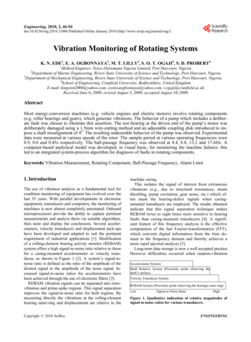
3.2 SOFTWARE INSTALLATIONMetrix provides the DPS Configuration and Utility Software on a USB memory stick that yourequest with the DPS (Refer to the DPS datasheet for software ordering information.)Insert the USB stick into your computer and open explorer to view the files.Double-click the version for your operation system according to Table 2 and follow theinstructions listed on the following pages.Table 2: Operating System vs. VersionOperating SystemVersionWindows XPDPSUser.exe (32 bit)Windows 7DPSUser x64.exe (64 bit)Click Next to continueFigure 1: Software Installation Splash ScreenDoc# 100576 REV C (Sept 2017) Page 7 of 42
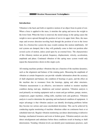
Figure 2 shows the end user license agreement. Click ‘Accept” to continueFigure 2: License AgreementClick Install to begin the installationFigure 3: Installation ScreenDoc# 100576 REV C (Sept 2017) Page 8 of 42
If you are running Windows 7, Windows may present a User Account Control notice asshown in Figure 4. Click “Yes” to continue.Figure 4: Windows 7 User Account ControlYou may additionally see a Windows Security notice as shown in Figure 5. Click ”Install thisdriver software anyway” to continue.Figure 5: Windows 7 Security ControlDoc# 100576 REV C (Sept 2017) Page 9 of 42
Click the Finish button as shown in Figure 6 to close the installation process.Figure 6: Installation Complete ScreenDoc# 100576 REV C (Sept 2017) Page 10 of 42
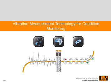
3.3 CONNECTING THE DPS TO A COMPUTERFollow these steps to access the DPS USB connector for connection to a computer.3.3.1 REMOVE THE BASERemove the three screws from the DPS base to access the mini USB connector as shown inFigure 7 and Figure 8.Remove these three screws toremove the baseFigure 7: Removing the BasePlug the mini-USB connectorinto the DPS PlugFigure 8: The USB PlugPlug the USB A connector into an available USB port on your computer.Doc# 100576 REV C (Sept 2017) Page 11 of 42
3.3.2 APPLY POWERYou must apply 24 Vdc power to the DPS while configuring as shown in Figure 9. Note thatyou can use either a negative or positive power supply (Refer to the DPS datasheet for voltage and current requirements.) Powering is the same for either the MX2033 or the MX2034.The MX2034 does not require load resistors when configuring.Common-24VFigure 9: Powering the DPSNOTE: Install the software before connecting and powering the DPS to ensure the computer finds the correctUSB driver3.4 LAUNCHING THE DPS CONFIGURATION SOFTWARELaunch the DPS Configuration Software by double-clicking the icon:Doc# 100576 REV C (Sept 2017) Page 12 of 42 24VCo
Digital Proximity System Operation and Maintenance Manual 100576 REV C The DPS (Digital Proximity System) devices consists of two modules: the MX2033 and MX2034. The MX2033 is a conventional 3-wire driver while the MX2034 is a two-wire current loop transmitter. Users can con-figure either unit to measure peak-to-peak vibration, gap distance, or rotational speed. These products are