Transcription
Mahmood: Developing the design of the Etherchannel switch for the enhancement of theDeveloping the design of the Etherchannel switch for theenhancement of the Quality of Service (QoS) performanceBasil Sh. MahmoodCollege of Electronics engineering/University of MosulAbstractQuality of Service (QoS) mechanisms provide the necessary level of services(bandwidth and delay) to any application in order to maintain an expected quality level. Thispaper studies the effect of adopting QoS on the performance of (real time) system like videoconferencing. A simulation model of the real time network is built using OPNET package.The various parameters affecting the system performance are determined and differentsolutions to enhance the system performance are suggested .A modified switch architecture isproposed to enhance the real time performance of the system and to modify its quality ofservice capability .The modification includes adding Etherchannel unit which can classifydata into real time or non-real time data and direct each data packet to the appropriate channel.The architecture of the Etherchannel unit is described by VHDL programming and built onFPGA chip .Accordingly , the modified switch is found to need only extra seven clock pulsesto classify each data packet .Keywords: Quality of Service (QoS), Switched Ethernet, UDP, TCP, FPGA,VHDL(QoS)/.(OPNET).(FPGA).(VHDL).Received 27 Nov. 2007Accepted 16 June 200860
Al-Rafidain EngineeringVol.17No.3June 20091. Quality of Service (QoS) –An IntroductionQuality of Service (QoS) means the possibility to classify different traffic streams andto qualify the performance for each traffic stream across a network. The role of QoS becomesobvious when various types of traffic for different users are utilized by heavy network.Therefore, QoS can offer better service when necessary [1]Although many network protocols have been providing QoS solutions for a number ofyears, the relatively low cost of the Ethernet infrastructure has made QoS solutions morepopular edge technology. Therefore, over 85% world wide LAN Ethernets have been drivento QoS expansion network. Ethernet performance can be improved by increasing itsbandwidth and this was previously enough for most of the applications. Now manyapplications such as video and voice demand increases in the bandwidth in rates faster thanthe increase in the supply of bandwidth ,such applications more or less become QoSdependent .Therefore, QoS becomes a better solution and introduced instead of altering theinfrastructure of many worldwide network. [2]Instead of paying for the extra cost of the extra bandwidth, administrator of thenetwork must care on the quality of service (Qos) so that traffic management becomes morerobust and the key to the network quality of service.2. Traffic Characteristics of Network ProtocolsThe most commonly used network protocols today are TCP (Transport ControlProtocol) and UDP (User Datagram Protocol). According to the characteristics of these twoprotocols, the network traffic flows (packets that are associated with the same application andsession) can be analyzed so that their performances can be improved according the influenceson the QoS requirements [3].TCP has proven to be a rugged, durable protocol, in continuous use since 1974.Almost all widely implemented Internet applications use TCP as the network protocol.However, TCP has a lot of protocol and data overhead. In contrast, UDP is a much simplerprotocol. However, several key features of TCP network traffic management are lost. Thebenefits of TCP are obvious if the application needs a reliable, connection-oriented way ofcommunicating. Well-known examples of protocols using TCP are HTTP (the WWWprotocol), FTP (File Transfer Protocol), and Telnet (Terminal Protocol) [3-5].Since TCP flow can adapt to the available bandwidth then, combining several TCPflows on the same network connection may be done without special precautions, as theirnative behavior is to adapt to the available bandwidth. The TCP back-off mechanismeffectively enables the different flows to share the available bandwidth over time. However,although bandwidth distribution will be fair over long periods of time, it is likely that therewould be large variations between the currently most aggressive and least aggressive flow inany given short (milliseconds) time frame. This unfairness is due to variations in round-triptime (RTT) between different flows; a flow with a shorter RTT can recuperate faster fromslow-start and so will get a larger share of the available bandwidth than flows with longerRTTs. Therefore combined TCP flows may still benefit from QoS handling.The benefits of UDP are that data loss does not trigger time-outs or retransmission.This makes UDP the preferred protocol for delay and jitter sensitive applications, such asvoice and video transmission , in which it is better to have a short period of silence ormomentarily blank picture than to have big fluctuations in samples or frames per second.Techniques that prevent and lessen these effects exist for TCP, but UDP has proven to bemore reliable for real-time applications [6].This paper deals with a situation in which TCP and UDP traffic are competing on thenetwork resources. Different video conferencing schemes are assumed to be the real time61
Mahmood: Developing the design of the Etherchannel switch for the enhancement of thetraffic which are affected by various TCP traffic intensities. Quality of Service isimplemented using different techniques and accordingly a new switch architecture issuggested.3. QoS in Switches and RoutersUsually quality of service is executed in the switches and routers directing trafficthrough the network infrastructure. In a switch or a router there are four distinct metrics thatdetermine QoS: Latency (the delay a flow experiences when passing through a device), jitter(latency variations), bandwidth distribution and availability (throughput or goodput) and lossprobability[7].Control over latency and jitter is important for the services like voice and video thatincreasingly being offered over different types of networks and the Internet. Low latency isimportant for interactive services, such as a video conference or a simple telephone call (forexample, the human ear will pick up latencies greater than 300ms). Latency is not asimportant for non-interactive services such as streaming video and listening to a radiobroadcast transmitted over the Internet. Here, jitter (latency variation) is more important sincethe receiver needs to buffer information to compensate for latency variations.Latency is the most important metric for videoconferencing application. There arebasically four origins of latency in a network [8].packet transmission time (Packet length / Data rate)Propagation delay ( Cable length / Wave speed on that cable)(Propagation delay in LAN is relatively small and could be neglected)Switch delay (electronic circuits delay queuing delay)Delay in the TCP/IP stack inside the transmitting and receiving nodes.4. Enhancing QoS Capability by Modifying Etherchannel TechnologyEtherChannel technology builds upon standards-based 802.3 full-duplex Fast Ethernetto provide network managers a reliable, high-speed solution for the network backbone.EtherChannel technology can offer bandwidth scalability with full-duplex increments of 200Mbps to 8 Gbps [9].The switch (which supports EtherChannel) distributes frames across the ports inan EtherChannel according to the source and destination Media Access Control (MAC)addresses. The operation that determines which link in an EtherChannel is used , is verysimple. A connection across an EtherChannel is determined by the source - destinationaddress pairs. The switch performs an X-OR operation on the last two bits of the sourceMAC address and the destination MAC address. This operation yields one of fourpossible results: (0 0), (0 1), (1 0), or (1 1). Each of these values points to a link in theEtherChannel bundle. Also, various load balancing techniques is used to guarantee fairdistribution of traffic between the channels. When the load on a channel exceeds (1%) ofits capacity, it is directed to other less load channels [9,10].EtherChannel technology provides many benefits such as high bandwidth, loadsharing and redundancy. This technology provides load balancing and management of eachlink by distributing traffic across the multiple links in the channel. Unicast, multicast, andbroadcast traffic is distributed across the links in the channel. In addition , EtherChanneltechnology provides redundancy in the event of link failure. If a link is cut in anEtherChannel, traffic is rerouted to one of the other links in less than a few milliseconds, andthe convergence is transparent to the user [9,10].62
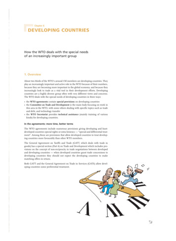
Al-Rafidain EngineeringVol.17No.3June 2009In this paper, EtherChannel is used to enhance QoS performance of switched Ethernetand to solve network delay problem caused by the network congestion. EtherChannel wasassumed to be installed between the ports that connect the network switches together (refer tofigure 1).Nowadays , switches that can handle QoS ,they do that softwarely . In this paper , ahardware modification to the switch architecture is developed in order to handle QoShardwarely. The main idea behind introducing this design , is to separate real time data fromnon real time data. Figure (1), shows the architecture of the proposed switch. As shown, themodification is performed on the Etherchannel controller unit.Figure (1): Architecture of the proposed switch.The operation of the new switch can be described as follows:1. A new unit called “packets classification and forwarding unit” was added to theEtherchannel unit. Its duty is to classify and forward the packets to one of the switch ports asshown in figure(1). Packet classification is crucial for QoS because it enables the switch orrouter to differentiate the traffic streams and treat them differently depending on theirindividual requirements. Classification can be divided into two parts; data extraction, wherethe relevant fields are extracted from the packet header, and data comparison, where theextracted fields are compared to predefined data.2. When a packet arrives the switch, its “protocol type ” fields(at the layer 3 header as shownin Figure(2)) is checked by the packets classification and forwarding unit and then forwardsthe packet to one of the ports. This arrangement guarantees full isolation between the twotraffic types.3. Each EtherChannel is reserved to one of the traffic types, i.e., the outgoing packets aredirectly forwarded (by the EtherChannel controller) to one of these channels.63
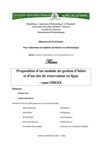
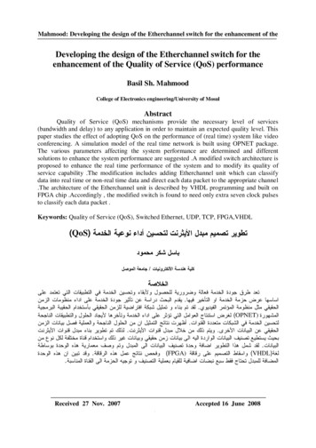
Mahmood: Developing the design of the Etherchannel switch for the enhancement of theDestinationAddress (6Bytes)Source Address (6Bytes)Length(2 Bytes)Data and Padding(Up to 1500Bytes)CRC (4 Bytes)Figure(2): Ethernet & IP Layer Header Format5. The Simulation ModelIn order to study the QoS performance of a switched Ethernet under differentcircumstances, an OPNET simulation model was built[11]. The model shown in figure (3)consists of a Fast Ethernet LAN connecting different videoconferencing clients arranged asgroups. The Video performance is ((160x125) pixel ,8 bit colour intensity, 30 frame/sec.).Also , the model has two TCP Traffic generators exchanging full duplex TCP Traffic indifferent rates. On the other side, there are four servers for the video conferencing groups .Switches sw1 and sw2 connect the clients groups and the server groups along with the TCPgenerators.Figure(3): The Simulation Model64
Al-Rafidain EngineeringVol.17No.3June 2009The first investigation of the system performance(videoconferencing Latency)includes varying the number of clients in each group and ,hence, the total number ofusers(with certain TCP traffic contribution). As a result of simulation, figure (4) shows thatthe unmanaged increment in the number of users could heavily affect the latency because ofthe bandwidth congestion problem.Figure(4): Latency Variation vs. Number of UsersIn order to investigate the effect of the TCP traffic on the system performance, the numberof clients is fixed to be (50,100,150). In the beginning , the TCP traffic generators wereconnected to switch (SW1). The two nodes exchange a TCP data with a total rate of 100Mbps on the line. It is noticed that the variation in latency when measured for differentnumber of clients in the networks no more than (1%). This little increase assures theaffectivity of the non blocking property of the switch. This property allows any two ports toexchange data without disturbing or blocking other ports on the switch.Now returning to figure (3), the load between the TCP traffic generators when variedfrom (0 to 100 Mbps), the maximum latency is measured. Figure (5) indicates that thenetwork delay becomes more effective when the offered load exceeds (25Mbps), and thenetwork becomes more congested when the load exceeds a value of (40Mbps ).Figure(5):Latency Variation vs. TCP Offered Load(real-time offered load is fixed)65
Mahmood: Developing the design of the Etherchannel switch for the enhancement of theThe main reason beyond the increase in the network delay, and hence the latency, isthe competition between different traffic types. When the packets moved from a switch toanother, they pass through the ports that connect the two switches. When the load increases,more packets try to pass these ports and generate more queuing delay inside the switch (thebottle neck point).When the offered load becomes very high, the queued packets inside the switchesoccupy most of its memory, which force the switch's controller to take one ( or both) of thefollowing two actions[12]:1.Removing the packets that spent a specific time inside the switch's memory(Agedpackets),according to the FIFO principles.2. Suspend accepting any further packets.These network conditions, add a very high delay to the packets travelling time (somepackets my not reach their destinations at all). Figure (6) shows the latency increments withtime when a heavy load (100 Mbps) is offered to the network. The unlimited increase in thelatency, breaks down the whole network operation.Figure(6): Latency Variation Over Simulation Time6. Solving Network Delay Problem:Network delay problem can be solved by either limiting the non real-time traffic (TCPtraffic) offered to the network, or by increasing the channel bandwidth between the switches.The first solution was achieved by limiting the network connection to the TCP trafficgenerators nodes via (10 Mbps). The other solution uses either EtherChannel technology or 10Gigabit Ethernet to increase the bandwidth between the switches. These solutions were testedby the OPNET environment, assuming the presence of a (1000 Mbps) TCP traffic and 100clients (worst possible case).6.1 Limiting Non Real-Time Traffic:This solution is the easiest and cheapest option. The ports to which TCP traffic nodes areconnected, could be reconfigured to work at 10 Mbps speed. Accordingly, higher bit rate canbe assigned to the non real time traffic contribution, and the network delay is greatlyminimized. The simulation results as referred to figure(5) show a very stable networkbehaviour in the presence of the (10 Mbps) traffic and the latencies keep their values withoutany change. However, this limitation could affect negatively on the applications workingaccording to the TCP/IP protocol.66
Al-Rafidain EngineeringVol.17No.3June 20096.2 Using 10 Gigabit Ethernet Technology to Increase Channel Bandwidth:As known, 10 Gigabit Ethernet is a new technology used to enhance channelthroughput in many fields. In this paper, it is used to connect the network switches together,which increases the bandwidth between them to 10 Gbps. This arrangement allows both realtime data and non real time data to be existed on the same network without disturbing eachother. The simulation of the model in figure(3) gives a latency value of (0.0057 Sec.).However, 10 Gigabit Ethernet represents the highest cost option [9].6.3 Using the Modified EtherChannel Technology to Increase Channel BandwidthIn OPNET environment, the number of EtherChannels and their speed were varied,i.e. , the channel bandwidth. The goal is to find the necessary amount of channel bandwidth tohandle the load offered to the network without affecting its latency values. Table (1) lists thevarious possibilities of channels and their corresponding latency values. It is obvious that (4Channels , 1 Gbps ) option gives the best latency results. However, network delay problemcould not be completely vanished because the system fails to respond to the real time deadlinetime of (300 mSec.)Table (1); Maximum latency for various possibilities of channelsNumber of ChannelsChannel speed( Mbps)Maximum Latency(Sec.)10001.751000110000.65In spite of the relative advantage behind using Etherchannel technique, simulationresults show that the average utilization of each EtherChannel in the case of (4 Channels , 1Gbps), does not exceed (26%). It is obvious that the offered load consumes only a smallportion of the channels bandwidth, which can be considered as a waste of bandwidth andunnecessary additional cost.The characteristics of the proposed architecture were described and added in theOPNET environment. The speed of the two EtherChannels(channel 1 and channel 2 of figure1) was chosen to be (1000 Mbps). The results obtained from running the simulation show thatthe proposed switch architecture is able to fully isolate the two traffic types (inside andoutside the switch) . As shown in Figure(7) ,the latency curve for the modified Etherchannelis similar to that in Figure(4) for 0% TCP load when using the traditional Etherchannel . Thisassures the fully isolation of the two traffic types. This arrangement removes the negativeeffect of Ethernet delay on latency. In addition, the use of two (1000 Mbps) EtherChannelskeeps the cost to the lower possible value.Finally, it is possible to say that using the modified EtherChannel technology (Separatedtraffic types Separated transmission channels) greatly enhances the Quality of Servicecapability of the system.124Figure (7) : Enhancement of System Performance Using Modified Etherchannel technique67
Mahmood: Developing the design of the Etherchannel switch for the enhancement of the7. Hardware Implementation of the Suggested Solution:In order to investigate the effects of the proposed hardware changes on the switch’sarchitecture, a VHDL program is built to describe the function of the modified Etherchannelunit mentioned above. Then, the design was implemented in FPGA using Spartan 3evaluation kit.[13]In this paper, 32 bit-bus architecture type , due to its wide spread [14], was chosen to bethe architecture of the proposed switch, see figure (1 ).Figure (8) shows the logical and pin diagram of the proposed Etherchannel unit , whiletable (2) lists the functional description of these pins.D31-D0EtherchannelControllerHOLDActv PRTPRGCLKPacketClassification UnitRESETFigure (8): The logical and pin diagram of the proposed Etherchannel unitTable(2): The pin description of the proposed Etherchannel unitPinD0-D31PRGActv PRTHoldDescriptionData lines of the unitChoose the operational mode of the unitChoose one of the portsSuspend the packet transfer operationResetReset the unitCLKSystem Clock68FunctionTransfer data to/from theunit‘0’ operation mode‘1’ programming mode‘1’ TCP Port‘0’ UDP Port‘0’ don’t hold‘1’ hold‘0’ Unit is active‘1’ Unit is not active
Al-Rafidain EngineeringVol.17No.3June 2009Packet classification unit is added to the traditional architecture of the switch. Thisunit classifies the incoming streams of data into TCP and UDP packets according to theirheaders in the second and third layers of the TCP/IP network model. The headers formats ofthese layers were shown earlier in figure(2). Packet classification unit mainly consists of twoparts; data extraction part, where the relevant fields are extracted from the packet header, anddata comparison part, where the extracted data fields are compared to predefined data.Static part of the packet may be picked and sent to the comparator. Although thismethod of data extraction is simple but has some drawbacks. For example, it can not detectthe presence of a VLAN tag.Dynamic Packet Decoding is a. more flexible method of extracting the headerinformation. The dynamic packet decoder is based on the type of protocol and therefore it isprotocol-aware and is able to filter out the relevant fields of a packet wherever they may bewithin the packet. This arrangement was achieved using programmable offset technique inwhich offset value is added to recover against the different situations (see figure 8).Data comparison also made to be executed in different ways . The simplest method isto compare all extracted data fields with a ternary bitmask and to report if there is a packetmatch or not. The modified Etherchannel unit may work in one of two modes; programmingmode or operation mode .I. Programming Mode: When the signal on pin PRG is '1', the modified Etherchannel unitworks in the programming mode, in which the offset value is entered to the device. Thesequence of events in this mode is as follows:1. PRG signal is '1'.2. HOLD signal is '0'.3. The offset value is fed to the offset buffer via the 32 bit data bus and fed to the upcounter ( as shown in figure 8) as a threshold value.The above three steps are executed in only one clock cycle.II. Operation mode: This is the mode in which modified Etherchannel unit performs itspackets forwarding functions depending on their transport layer protocols. It is summarized asfollows:1. Whenever a packet is transferred through the switch fabric, its layer two header(14 bytes)and the beginning of layer three header (10 bytes) are stored inside an 24 Bytes temporarybuffer, see figure(2) . This operation requires 6 clock periods since the bus is 32 bit width.2. The packet classification unit generates a ‘HOLD’ signal to pause the packet transferprocedure until finding its destination port . The HOLD signal is generated as a result ofcomparing the output of an 8 bit counter with a predefined value (represents No. of clocks)inside the latched HOLD signal unit.3. The comparison process between the predefined protocol type field (8 bit) and the packetis achieved. When the protocol type value is 17(for UDP), then the packet is directed toEth ch1, Other packet types is forwarded to the second port(Eth ch2).This step requiresone clock cycle.4. After completing the comparison process, the packet classification unit transfers thepacket’s header fields to the proper port by activating the signal Actv PRT to low (figure8). Again, it needs 6 clocks to finish this operation.5. The ‘HOLD’ signal is returned to “0” and ‘Reset’ signal become ‘1’ to deactivate the unitand to allow the completion of the packet transfer operation to its proper port. In order tosimulate the behavior of the packet classification unit , the above modes were described as aVHDL program. Both packet classification unit and the switch bus are assumed to work at aclock frequency of (50 MHZ).Also, the packet is assumed to have the following fields values : destination & source MACaddresses are (1A2867D01212, 121212121212) respectively, Version is 4 (i.e. IPV4), Header69
Mahmood: Developing the design of the Etherchannel switch for the enhancement of thelength is 5 (i.e. 20 Byte) , Service Type is 00 (i.e. Normal service), Overall Length (0060)Hex.,Identification number is (1212)Hex., Flags & Fragmentation offset are (4000)Hex. (i.e. NoFragmentation), Time to live is (64)Hex. , Protocol is (17)Hex. (i.e. UDP). The results obtainedfrom running the VHDL program are shown in the timing diagrams of figure(9).Figure(9): The timing diagram of the VHDL Simulation for the modified switchIt is clear that packet classification unit adds a 7 clocks delay period to the packet transferoperation to the port buffers. For ( 50 MHZ ) clock, this period is equal to ( 0.14 Sec.). Thisdelay could be minimized further by using higher clock values.In order to explore the synthesis possibility of the VHDL program, an FPGA Spartan 3 starterkit is used to be the implementation target of the design. Spartan 3 has the following features[13]:Maximum working frequency of (50 MHz).200,000-gate Xilinx Spartan-3 XC3S200 FPGATwelve 18K-bit block RAMs (216K bits)Twelve 18x18 hardware multipliersFour Digital Clock Managers (DCMs)Up to 173 user-defined I/O signalsThe statistics obtained from implementing the VHDL program of the modified switch usingISE project navigator package) are listed in table (3).Table (3): Statistics obtained from FPGA implementationStatisticProportionProportion%No. of used CLBs130 out of 19206No. of used Flip Flops82 out of 3,8402Number of 4 input LUTs229 out of 3,8405Number of bonded IOBs37 out of 17321Number of GCLKs1 out of 812Max. operating Frequency : 224 MHzDevice Throughput (bus width maximum frequency )/ number of clocks to finish an operation cycle (32*224) / 13 551 Mbps70
Al-Rafidain EngineeringVol.17No.3June 20098. ConclusionsThe Quality of Service offered on a network rests on the ability to separate traffic into classesand to treat these classes differently in order to distribute the available bandwidth and toprovide traffic prioritization. Latency and jitter control are the more important as real-timemedia applications, such as streaming video and video conferencing, take hold in the networkworld. This paper investigates the effect of mixing two traffic types , real time traffic and nonreal time traffic. An OPNET simulation model was built for this purpose. It was found that theunmanaged traffic could affect dangerously on the system performance and different traffictypes could affect negatively on each other. In order to implement QoS concepts on thenetwork , a new switch architecture is proposed. The suggested solution adopts twotechniques to enhance the operation of the network. The different traffic types were isolatedusing separate buffers inside the switches(one for each traffic type) and routed to differentchannels between the switches. The adoption of this technique would enhance theperformance of the network and introduce the concept of the multi purpose network. Thistechnique needs only an extra 7 clocks cycles ,while it fully isolates the two different types oftraffic.References1. Soucek, S. and Sauter, T., Quality of service concerns in IP-based control systems. IEEETransactions on Industrial Electronics, 51:1249– 1258, December 2004.2.Armitage, G. Quality of service in IP networks: Foundations for a multi-service Internet.Indianapolis: Macmillan Technical Publishing, (2000).3.Adams, K., & Bawany, K. Quality of service over IP networks. Gartner Research Inc.,(2001).4. R. West and K. Schwan , "Quality events: a flexible mechanism for quality of servicemanagement", Seventh IEEE Symposium Real-Time Technology and Applications, 2001.,30 May-1 June 2001 Page(s):95 - 1045. Kornegay, K.T.; Gang Qu; Potkonjak, M.;" Quality of service and system design".Proceedings IEEE Computer Society Workshop On VLSI '99, 8-9 April 1999 Page(s):112 1176.Subramanyan, B. ,”Real-Time Networking for Quality of Service on TDM basedEthernet”,MSC, Department of Electrical Engineering and Computer Science, University ofKansas,20017. Amirijoo, M.; Chaufette, N.; Hansson, J.; Son, S.H.; Gunnarsson, S.;" Generalizedperformance management of multi-class real-time imprecise data services",26th IEEE International Real-Time Systems Symposium, 2005. RTSS 2005. 5-8 Dec. 2005 .8.Chatterjee, S., Abhichandani, T., Tulu, B., & Li, H. SIP-based enterprise convergednetwork for voice/video over IP: Implementation and evaluation of components, (2005).9.Cisco Systems. Internetworking technology handbook. Indianapolis: Cisco Publication,(2001).10.Cisco Systems .packet-switching performance over the Fast EtherChannel bundle. CiscoPublication , 2003.11. Deora, V. ; Shao, J. ; Gray , W.A. ; Fiddian N.J. ; " Modelling Quality of Service inServiceOriented Computing" ; Second IEEE International Workshop Service-Oriented SystemEngineering, 2006. SOSE'06. Oct. 2006 Page(s):95 - 10112.Hiller, K., “LAN switching: Overview”, Gartner Research Inc., (2002).13. Xilinx Inc. official site: http//:www.Xilinx.com14.Fineberg, V. “A practical architecture for implementing end-to-end QoS in an IP network”,IEEE Communications Magazine, Vol.40,p122-130,(2002).The work was carried out at the college of Engg. University of Mosul71
EtherChannel bundle. Also, various load balancing techniques is used to guarantee fair distribution of traffic between the channels. When the load on a channel exceeds (1%) of its capacity, it is directed to other less load channels [9,10]. EtherChannel technology provides many benefits such as high bandwidth, load sharing and redundancy.