Transcription
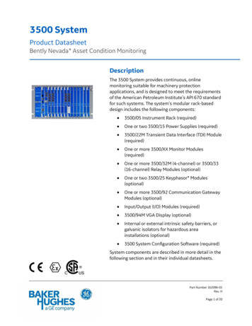
3500 SystemProduct DatasheetBently Nevada* Asset Condition MonitoringDescriptionThe 3500 System provides continuous, onlinemonitoring suitable for machinery protectionapplications, and is designed to meet the requirementsof the American Petroleum Institute’s API 670 standardfor such systems. The system’s modular rack-baseddesign includes the following components: 3500/05 Instrument Rack (required) One or two 3500/15 Power Supplies (required) 3500/22M Transient Data Interface (TDI) Module(required) One or more 3500/XX Monitor Modules(required) One or more 3500/32M (4-channel) or 3500/33(16-channel) Relay Modules (optional) One or two 3500/25 Keyphasor* Modules(optional) One or more 3500/92 Communication GatewayModules (optional) Input/Output (I/O) Modules (required) 3500/94M VGA Display (optional) Internal or external intrinsic safety barriers, orgalvanic isolators for hazardous areainstallations (optional) 3500 System Configuration Software (required)System components are described in more detail in thefollowing section and in their individual datasheets.Part Number 162096-01Rev. HPage 1 of 20
System ComponentsThis section describes the individualcomponents that make up a complete3500 system.Instrument RackThe standard 3500 Rack is available in 19”EIA rail-mount, panel-cutout-mount, andbulkhead-mount versions.Bulkhead Mount Version19” EIA Rail or Panel Mount VersionThe rack provides slots for two PowerSupplies and a TDI in the left-most rackpositions that are reserved exclusively forthese modules. The remaining 14 slots inthe rack can accommodate anycombination of monitor, display, relay,Keyphasor module, and communicationgateway modules.All modules plug into the rack’s backplaneand consist of a main module and anassociated I/O module. The I/O moduleinstalls at the rear of the rack for panelmount systems, and above the mainmodule for bulkhead-mount systems.Mini RackA mini rack (12” wide instead of 19”) isalso available and features 7 availablemonitor slots instead of 14. Like its largercounterpart, the left-most slots arereserved for the Power Supply or Suppliesand TDI Module.The mini rack may be mounted in a panelcutout or, using an optional adapter plate,on 19” EIA mounting rails. Bulkheadmounting is not available.Standard rack depth is 349 mm (13.75inches), while bulkhead mount rack depthis 267 mm (10.5 inches). NEMA 4 and 4Xweatherproof housings are available whenrequired for environmental protection orwhen purge air is used.Part Number 162096-01Rev. HPage 2 of 20
Power SupplyThe 3500/15 Power Supplycan be ordered for ac or dcinput power, providingcompatibility with voltagesources worldwide. Linenoise filters are standard.The 3500 Rack canoperate from a singlesupply, or dual suppliescan be used to provideredundancy for situationsthat cannot tolerate power interruption.Dual supplies reside in the upper andlower positions of the left-most rack slot.Redundant supplies can use separatevoltage sources. For example, the primary(lower) supply can operate with 120 Vacpower while the backup (upper) supplycan be powered from an uninterruptible24 Vdc source.Each supply can individually providepower to the entire rack and its modules.When redundant supplies are used, thelower supply acts as primary power forthe rack while the upper supply acts as abackup, ready to instantly andautomatically operate as the primary racksupply without interrupting rack functionsshould the primary supply fail.The 3500/15 Power Supply module hasself-monitoring functions that allow it todetermine if all its output voltages arewithin specifications. The moduleannunciates this via a green Supply OKLED on the power supply’s front panel.Transient Data Interface (TDI)The TDI is the 3500 Rack’sprimary interface to theconfiguration, display, andcondition monitoringsoftware. Each rack requiresone TDI, located in the rackslot immediately adjacent tothe power supply slot.The TDI supports aproprietary protocol used bythe 3500 ConfigurationSoftware to configure therack and the 3500 OperatorDisplay Software to retrieverack data and statuses.The TDI also provides a directinterface with System 1*Condition Monitoring andDiagnostic software withoutthe need for an externalcommunications processor.The Rack OK relay is locatedwithin the TDI’s I/O module.It is driven by NOT OK conditions withinthe TDI itself and within other modules inthe rack.Note: Dozens of possible events within therack can drive the Rack OK relay to NOT OKcondition. For this reason, the Rack OK relay it isnot intended for use as part of a machinery autoshutdown circuit. It should be used for generalannunciation purposes only.The TDI supports self-monitoringfunctions both for itself and for the rack, inaddition to those provided by theindividual monitor, relay, communications,and other modules. While the TDI providescertain functions common to the entirePart Number 162096-01Rev. HPage 3 of 20
rack, it is not part of the critical monitoringpath and its machinery protectionfunctions.The TDI has four front-panel LEDs thatprovide the following indications:OKTX/RXTMCONFIGOKIndicates that the TDI Module and itsI/O Module are operating correctly.Flashes at the rate thatcommunications between the TDIand other rack modules areoccurring.Indicates when the rack is in the TripMultiply mode.Indicates that any module in therack is not configured or has aconfiguration error; that the storedconfiguration of the TDI does notmatch the physical configuration ofthe rack; or that a security optioncondition was not met.System configuration is secured by meansof a keylock switch on the front of the TDIand two levels of software passwordprotection, preventing unauthorizedchanges to or tampering with theconfiguration settings.The TDI can be connected to a portablecomputer via a front-panel USBcommunications port for local changes toconfiguration. The TDI providespermanent system connectivity viaEthernet ports. It also provides a frontpanel DIP switch for assigning a uniquerack address when multiple 3500 racksare networked with one another.The TDI has a system reset switch on thefront panel for clearing any latched alarmsin the system as well as latched NOT OKconditions. The I/O module provides a setof rear-panel connections, which facilitateremote activation of the System Reset,Trip Multiply and Rack Alarm Inhibitfunctions.Monitor ModulesEach monitor occupies asingle slot out of 14available in the rack.Monitors aremicroprocessor-based andoffer digitally adjustableAlert and Danger setpointsfor each channel. Alarmscan be configured for eitherlatching or non-latchingoperation.Status indications for eachmonitor are provided byfront-panel LEDs, allowingobservation withoutoperator interaction forconvenient operation.Most monitors provideindependent 4 to 20 mAproportional outputs foreach channel of the I/Omodule for connection toassociated industrialsystems.Where applicable, the I/Omodules provide transducers withappropriate power via short-circuitprotected terminals. OK detectionroutines within each monitor continuouslycheck the integrity of each transducer andassociated field wiring.Transducer input signals are buffered andsent to front-panel BNC connectors for allmonitors except the 3500/60, /61, /65(temperature) and /62 (process variable)monitors.Part Number 162096-01Rev. HPage 4 of 20
Note: In addition to the direct measurementmade by the monitor, many channel types providean enhanced data set consisting of a variety ofmeasured variables that depend on the monitortype and its configuration. For example, radialvibration channels include the basic overall (direct)vibration amplitude as well as gap voltage, 1Xfiltered amplitude, 1X filtered phase, 2X filteredamplitude, 2X filtered phase, Not 1X amplitude,and Smax.These additional measured variables are providedfor each channel, and ALERT alarm setpoints canbe established on each variable, as needed.DANGER alarm setpoints can be established onany measured variable value returned from eachchannel.3500 Series Monitor ModulesMonitorTypeChannel Types (footnotes)3500/40M 3500/42MRadial VibrationAxial (Thrust) PositionEccentricityDifferential Expansion (1)Same as 3500/40M, with thefollowing additional channeltypes: Number ofChannels(footnotes)Four (2, 3)350046M Hydro Radial Vibration (7)Hydro Stator-Mounted Air GapHydro AccelerationHydro ThrustHydro VelocityStator End WindingMultimode FunctionalityFour (3)3500/50M Rotor SpeedRotor AccelerationZero-SpeedReverse RotationRotor Acceleration2Zero Speed2Reverse Rotation2Two (8, 9)TemperatureDifferential TemperatureSix (10)3500/60 &/613500/623500/64M3500/70M3500/72MFour (2, 3)3500/77M Process VariablesSix (10, 11) Dynamic PressureFour (12) Impulse AccelAcceleration2Recip VelocityLow Frequency Recip VelocityFourReciprocating Compressor RodDrop / Rod Position / HypercompressorFour (3)Reciprocating CompressorCylinder Pressure, including: Acceleration (4)Velocity (4)Acceleration2 (4)Velocity2 (4)Circular Acceptance Region (5)Shaft Absolute3500/44M Aeroderivative Aeroderivative2Four3500/45 Axial (Thrust) Position Differential Expansion Standard Single RampFour (3)3500/82FourSuction PressureMaximum PressureMinimum PressureCompression RatioPeak Rod CompressionPeak Rod TensionDegree of Rod ReversalMotor Stator Insulation Monitor Leakage Current (each phase) Line Voltage (each phase) Temperature (up to threechannels)NineDifferential Expansion Non-Standard Single RampDifferential Expansion Dual Ramp DifferentialExpansion Complementary DifferentialExpansion Case Expansion9 Valve PositionPart Number 162096-01Rev. HPage 5 of 20
Monitor Module Footnotes1.Only standard differential expansioncapabilities provided. For ramp differentialexpansion and complementary inputdifferential expansion, use the 3500/45Position Monitor, instead.2.The 3500/42M provides individual 4 to 20 mAproportional outputs for each channel. The3500/40M does NOT provide 4 to 20 mAoutputs.3.The monitor channels are programmed inpairs and can perform up to two of thesefunctions at a time. Channels 1 and 2 canperform one function, while channels 3 and 4perform another (or the same) function.4.Channels configured for velocity oracceleration provide only direct amplitude.Channels configured for Velocity II orAcceleration II provide 1X amplitude/phaseand 2X amplitude/phase and bias voltage inaddition to direct amplitude.5.Any vibration channel can be configured forconventional “pie-shaped” acceptance regionalarms. When configured for circularacceptance regions, circular (rather than pieshaped) acceptance region alarms can beenabled. Refer to the 3500/42MOperations/Maintenance Manual foradditional information, or contact yournearest sales professional.6.Only channels 3 and 4 can be used for CaseExpansion measurements.7.The 3500/46M provides frequency responsecharacteristics suitable for use on machineswith very slow rotational speeds, such ashydraulic turbine/generator sets, which oftenoperate at speeds of 100 RPM or lower. Also,special signal conditioning and trackingfiltering is provided, allowing detection ofrough load zone operation, shear pin failure,and other hydro-specific conditions.8.The 3500/50M is not intended for use inoverspeed protection applications. Use the3701/55 Emergency Shutdown (ESD) system,instead.9.Both Zero Speed and Reverse Rotationchannel types require both channels of the3500/50 module, making it a single-channelmonitor when used in these configurations.10. The 3500/60 and 3500/61 provide identicalfunctions except the 3500/60 does not provide4 to 20 mA proportional outputs. When theseoutputs are required, use the 3500/61.11. The 3500/62 is designed to accept staticproportional signals such as 4 to 20 mA, 1 to 5Vdc, or any static proportional voltage signalbetween –10 and 10 Vdc. When dynamicsignals (i.e., those where waveforminformation is required) are used, a 3500/40Mor 3500/42M can often be programmed as acustom channel type, making the 3500 systemcompatible with virtually any static or dynamicsignal from pressure, level, temperature,vibration, flow, position, speed, or othertransducers. Consult the factory or your localBently Nevada sales professional for moreinformation.12. The 3500/64M is primarily intended formonitoring combustor pressure pulsationinstabilities (“humming”) in gas turbines.Note: Analog (4 to 20 mA) and digital(Modbus ) outputs from relay modules areintended for operator annunciation and trendingpurposes only, as they do not provide the faulttolerance or integrity necessary for highly reliablemachinery shutdown purposes. For theseapplications, the 3500/32M and /33 Relay Modules(described on the following page) should be used.Part Number 162096-01Rev. HPage 6 of 20
Relay ModulesThe 3500/32M and 3500/33Relay Modules provide a setof relays that can beprogrammed to actuatebased on alarm conditionsin other monitor modules inthe rack. The /32M module(left photo) uses doublepole double throw (DPDT)relays, while the /33 module(right photo) uses singlepole double throw (SPDT)relays. The /32M modulehas 4 DPDT relay channelsand the /33 unit has 16SPDT relay channels. The/33 can also be configuredto act as if it has DPDTrelays. Doing this will usetwo SPDT relays to performthe function of every DPDTrelay that is configured.Although relay modules arenot a required componentof the 3500 System, westrongly recommend usingthem as the most appropriate way tointegrate the 3500 System with automaticshutdown applications. Any number ofrelay modules can be placed in any of theslots to the right of the TDI.3500 System Configuration softwarefacilitates programing “Alarm Drive Logic”that controls relay actuation. This logiccan be based on various combinations ofalarms, ranging from an individualchannel’s Alert, Danger, or NOT OK statusto highly complex Boolean expressionsthat combine two or more channelstatuses to provide special AND or ORvoting.By adding the required numberof relay modules to the rack, iti
3500 System Product Datasheet Bently Nevada* Asset Condition Monitoring Description The 3500 System provides continuous, online monitoring suitable for machinery protection applications, and is designed to meet the requirements of the American Petroleum Institute’s API 670 standard for such systems. The system’s modular rack-basedFile Size: 1MBPage Count: 20