Transcription
Bentley Nevada 3500 System Architectureand Rack ConfigurationPresented by:Arfan Aliwww.arfanali.webs.com1
Introduction to Vibration The Oscillatory (back and forth) motion of amachine from its normal position of rest. Any motion that repeats itself after a specificinterval of time . Vibration Example :www.arfanali.webs.com2
Importance of Vibration MonitoringSystem Essential for Protection against machinery faultsPredict and diagnose crucial machinery Problems Imbalance Misalignment Shaft crack Bearing Failures and etc.Parameters to measure Thrust Vibration Speed Temperaturewww.arfanali.webs.com3
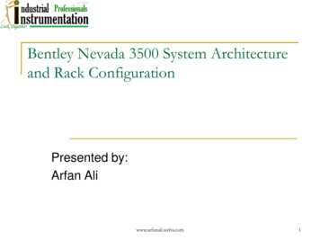
Monitoring SystemsBently NevadaMonitoring Systems7200 Series(Dial Monitoring)3500 Series(Computer Monitoring)we have two types of vibration monitoring system the Bently nevada 7200series vibration monitoring system. It is a dial monitoring analog systeminstalled at our plant on Air Compressor partially and on Most of the TPs etc.The second one is bently nevada 3500 series vibration monitoring system it iscomputer based digitized system installed at Syn compressor, Ammoniacommpressor, CO2 compressor and on Air compressor partially. The scope ofpresentation my presentation is limited to 3500 system only.www.arfanali.webs.com4
Features of 3500 Monitoring System State of art vibration monitoring systemProcessor based systemModular & Flexible ArchitectureTight integration with DCS using IndustryStandards InterfacesHot Insertion or Removal of ModulesProvides Enhanced Operator Information Windows based operator displayData can be displayed at multiple locationsImproved Reliability due to Redundant power supply and distribution networkTriple Modular Redundant Relay Moduleswww.arfanali.webs.com5
3500 Monitoring System Componentsand Layout Transducers3500 Rack3500 SoftwareComputersIndustrial ControlSystemTransducers on machinery3500 Rackwww.arfanali.webs.comComputer6
Vibration Monitoring System rBarrierShaftJunction Box3500 RackHost Computerwww.arfanali.webs.com7
3500 System MonitorRack Interface ModulesOne or twoPower SuppliesAny combination of thefollowing 14 slot positions Monitor Module Key Phasor Module Relay Module Temperature Modules Communication GatewayModulewww.arfanali.webs.com8
3500 Software PackagesSoftware PackageRackData AcquisitionConfigurationDDE ServerOperatorDisplaywww.arfanali.webs.com9
3500 Software SequenceSTARTConfigure RackUsing Rack ConfigurationDown LoadRack ConfigurationDesign Train DiagramUsing Software Configuration UtilityConnectData Acquisition/DDE ServerMonitor Data usingOperator Display Softwarewww.arfanali.webs.com10
Common Pitfalls Not OkBy PassInternal Faultswww.arfanali.webs.com11
Question & Answerswww.arfanali.webs.com12
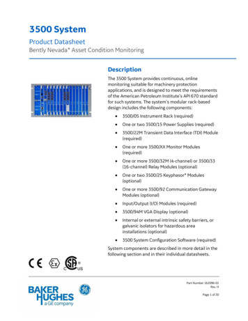
3500/15 AC & DC Power Supplies Half Height ModulesAlways Installed in the left most slotUpper Module. Primary SupplyLower Module. Backup SupplyRemoving & insertion of one Supply atone time will not disrupt operation.www.arfanali.webs.com13
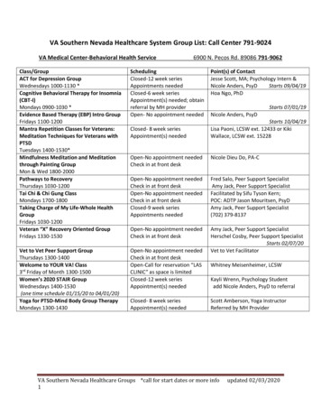
3500/20 Rack Interface Module (RIM) Must be located in the 1st SlotInterface card between the rack &monitoring computerWorks as a communication serverwww.arfanali.webs.com14
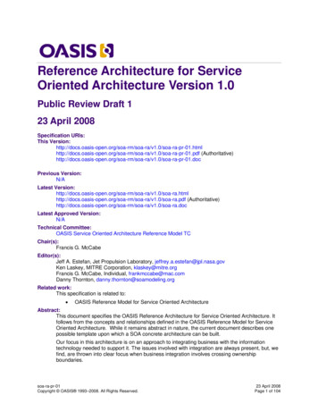
3500/42 Proximitor/Seismic Monitor Four Channel MonitorAccepts input from proximityand seismic transducersMonitor acceleration, velocityand absolute shaftmeasurement as wellwww.arfanali.webs.com15
3500/32 The 4 Channel Relay Module Full Height ModuleProvides Four Relay outputsProvide Alarm on Alert & tripping on DangersituationsProgrammable for AND/OR voting of tripRelayswww.arfanali.webs.com16
3500/40 Proximitor Monitor Four Channel MonitorAccepts input from proximity transducersMonitors Radial Vibration and Thrust Position Vibration 0- 500μm or 0- 20 mil Max.Thrust 40-0-40mil Max.Hold Alarm set points (Alert & Danger)Compare monitored values with Alarm set pointsProvide Input signal to Relay module, when the monitoredvalue exceed from the set pointwww.arfanali.webs.com17
3500/25 Key Phasor ModulesHalf Height module with 2-channelsMeasure RPM of the observed shaftView either Notch or Projection on the ShaftAssociation of key Phasor signal with peak to peakvibration is used to determine Vibration spectrumRange 1 to 99,999 RPMMaximum 4 key Phasor signals are possible in3500 SystemFront View 1.2.OK and TX/RXBuffered O/Pwww.arfanali.webs.com18
3500/61 Temperature Monitoring Full Height moduleSix channel MonitorAccepts both Thermocouple & RTD typeinputsProvide 4 to 20 mA recorder outputsNot in use at FFC-MMwww.arfanali.webs.com19
Rack Configuration Software onradial Vibration ChannelAxial vibration channelof Keyphasorof Relay modulewww.arfanali.webs.com20
Configuration of Radial Vibration Channel Transducer field installationRangeSet pointsKey phasorAlert latching / non latchingwww.arfanali.webs.com21
Configuration of Axial vibration channel Transducer field installationTowards / awayZero positionRangeSet pointsKey phasorAlert latching / non latchingTime delay1X, 2X and not 1Xwww.arfanali.webs.com22
Configuration of Key phasor AssociationRangeNotchwww.arfanali.webs.com23
Configuration of Relay Card Identify the XTs and VTs required for alarmsand dangerType of votingwww.arfanali.webs.com24
Software Configuration Utility Used to create MachineTrain DisplaysSpecify Historic trendparameters Enabling/DisablingTime B/W two consecutivepointsMemory SizeGenerate Report on MachineTrain Displayswww.arfanali.webs.com25
Data Acquisition/DDE Server Collects machinery monitoring Data, Alarm,and System Events dataProvides data to Operator Display SoftwareStores historical and real-time trend datawww.arfanali.webs.com26
Operator Display Software Displays machine monitoring data using Current valuesBargraphsTrends (Historical/Real)Machine Train DiagramsUsed to view System Event ListAlarm Event Listwww.arfanali.webs.com27
Current Valueswww.arfanali.webs.com28
Bargraphswww.arfanali.webs.com29
Trendswww.arfanali.webs.com30
Machine Train Diagramwww.arfanali.webs.com31
System Event Listwww.arfanali.webs.com32
Alarm Event Listwww.arfanali.webs.com33
Configuration of Radial VibrationChannelwww.arfanali.webs.com34
Configuration of Radial Vibration Channel(contd)www.arfanali.webs.com35
Configuration of Radial Vibration Channel(contd)www.arfanali.webs.com36
Configuration of Axial Vibration Channelwww.arfanali.webs.com37
Configuration of Axial Vibration Channel(contd)www.arfanali.webs.com38
KeyPhasor Module Configurationwww.arfanali.webs.com39
Relay Configurationwww.arfanali.webs.com40
Not OK Channel not ok status results from any of thefollowing conditions: Probe is openConnection looseness Note: If time defeat is ON 30 sec are required to move from not OKstate OK state When any channel go into Not okay state itwill go into bypass statewww.arfanali.webs.com41
By Pass A software switch is bypassing any channelalarming functionA transducer is not okay and the channel isconfigured for “Timed ok Channel Defeat”The Keyphasor associated with the channel hasgone invalidThe monitor has detected a serious internal faultwww.arfanali.webs.com42
Internal Fault Internal faults are rectified by checking thecode (event number) from the system eventlist and checking the corresponding value inthe system manual.www.arfanali.webs.com43
Key Phasorwww.arfanali.webs.com44
Shape of proximity probewww.arfanali.webs.com45
Negative Supply of Proximitor I am glad you benefited from my article. To answeryour question is that the first reliable transistors thatwere commonly available for use were NPN, whichrequired a negative supply .Mark Snyder, Bently Nevadawww.arfanali.webs.com46
we have two types of vibration monitoring system the Bently nevada 7200 series vibration monitoring system. It is a dial monitoring analog system installed at our plant on Air Compressor partially and on Most of the TPs etc. The second one is bently nevada 3500 series vibration monitoring system it is computer based digitized system installed at Syn compressor, Ammonia File Size: 772KBPage Count: 46