Transcription
nVision Operation Manualfor Reference Recorder
ContentsOverview . . . . . . . . . . . . . . . . . . . . . . . . . . . . . . . . . . . . . . . . . . . . . . . . . . . . . . . . . . . . . .1Absolute Pressure Specifications . . . . . . . . . . . . . . . . . . . . . . . . . . . . . . . . . . . . . . . . . . . 24Introduction. . . . . . . . . . . . . . . . . . . . . . . . . . . . . . . . . . . . . . . . . . . . . . . . . . . . . . . . . . . . . . 1Current, Voltage, and Switch Test (MA20) Module Instructions. . . . . . . . . . . . . . . . . . 25Quickstart. . . . . . . . . . . . . . . . . . . . . . . . . . . . . . . . . . . . . . . . . . . . . . . . . . . . . . . . . . . . . . . . 2Current, Voltage, and Switch Test (MA20) Module Specifications . . . . . . . . . . . . . . . . 27Functions . . . . . . . . . . . . . . . . . . . . . . . . . . . . . . . . . . . . . . . . . . . . . . . . . . . . . . . . . . . . .3On/Off. . . . . . . . . . . . . . . . . . . . . . . . . . . . . . . . . . . . . . . . . . . . . . . . . . . . . . . . . . . . . . . . . . . 3Measurements & Recording . . . . . . . . . . . . . . . . . . . . . . . . . . . . . . . . . . . . . . . . . . . . . . . . 3Numerical Display Overview. . . . . . . . . . . . . . . . . . . . . . . . . . . . . . . . . . . . . . . . . . . . . . . . 5Temperature (RTD100) Module Instructions . . . . . . . . . . . . . . . . . . . . . . . . . . . . . . . . . 29Temperature (RTD100) Module Specifications. . . . . . . . . . . . . . . . . . . . . . . . . . . . . . . . 32Resistance Temperature Detectors (RTD) . . . . . . . . . . . . . . . . . . . . . . . . . . . . . . . . . . . . 33Power . . . . . . . . . . . . . . . . . . . . . . . . . . . . . . . . . . . . . . . . . . . . . . . . . . . . . . . . . . . . . . . . .35Graphical Display Overview . . . . . . . . . . . . . . . . . . . . . . . . . . . . . . . . . . . . . . . . . . . . . . . . 5Battery Power . . . . . . . . . . . . . . . . . . . . . . . . . . . . . . . . . . . . . . . . . . . . . . . . . . . . . . . . . . . 35Graphing . . . . . . . . . . . . . . . . . . . . . . . . . . . . . . . . . . . . . . . . . . . . . . . . . . . . . . . . . . . . . . . . 6USB Power . . . . . . . . . . . . . . . . . . . . . . . . . . . . . . . . . . . . . . . . . . . . . . . . . . . . . . . . . . . . . . 37Averaging Mode. . . . . . . . . . . . . . . . . . . . . . . . . . . . . . . . . . . . . . . . . . . . . . . . . . . . . . . . . . 7Reset. . . . . . . . . . . . . . . . . . . . . . . . . . . . . . . . . . . . . . . . . . . . . . . . . . . . . . . . . . . . . . . . . . . 37Differential Mode . . . . . . . . . . . . . . . . . . . . . . . . . . . . . . . . . . . . . . . . . . . . . . . . . . . . . . . . . 7Run Tags. . . . . . . . . . . . . . . . . . . . . . . . . . . . . . . . . . . . . . . . . . . . . . . . . . . . . . . . . . . . . . . . . 8Chassis . . . . . . . . . . . . . . . . . . . . . . . . . . . . . . . . . . . . . . . . . . . . . . . . . . . . . . . . . . . . . . . . .Safety and Certifications . . . . . . . . . . . . . . . . . . . . . . . . . . . . . . . . . . . . . . . .38Hazardous Locations . . . . . . . . . . . . . . . . . . . . . . . . . . . . . . . . . . . . . . . . . . . . . . . . . . . . . 389Certifications. . . . . . . . . . . . . . . . . . . . . . . . . . . . . . . . . . . . . . . . . . . . . . . . . . . . . . . . . . . . 38Chassis Controls . . . . . . . . . . . . . . . . . . . . . . . . . . . . . . . . . . . . . . . . . . . . . . . . . . . . . . . . . . 9Multi-language Safety Instructions . . . . . . . . . . . . . . . . . . . . . . . . . . . . . . . . . . . . . . . . . 39Serial Numbers . . . . . . . . . . . . . . . . . . . . . . . . . . . . . . . . . . . . . . . . . . . . . . . . . . . . . . . . . . 13nVision Reference Recorder Specifications. . . . . . . . . . . . . . . . . . . . . . . . . . . . . . . . . . . 14Modules . . . . . . . . . . . . . . . . . . . . . . . . . . . . . . . . . . . . . . . . . . . . . . . . . . . . . . . . . . . . . . .Support . . . . . . . . . . . . . . . . . . . . . . . . . . . . . . . . . . . . . . . . . . . . . . . . . . . . . . . . . . . . . . .44Troubleshooting. . . . . . . . . . . . . . . . . . . . . . . . . . . . . . . . . . . . . . . . . . . . . . . . . . . . . . . . . 4415Calibration. . . . . . . . . . . . . . . . . . . . . . . . . . . . . . . . . . . . . . . . . . . . . . . . . . . . . . . . . . . . . . 46Module Installation Instructions. . . . . . . . . . . . . . . . . . . . . . . . . . . . . . . . . . . . . . . . . . . . 15Accessories and Replacement Parts. . . . . . . . . . . . . . . . . . . . . . . . . . . . . . . . . . . . . . . . . 47Pressure Module (PM) Instructions . . . . . . . . . . . . . . . . . . . . . . . . . . . . . . . . . . . . . . . . . 17Contact Us. . . . . . . . . . . . . . . . . . . . . . . . . . . . . . . . . . . . . . . . . . . . . . . . . . . . . . . . . . . . . . 48Pressure Module (PM) Specifications. . . . . . . . . . . . . . . . . . . . . . . . . . . . . . . . . . . . . . . . 18Trademarks . . . . . . . . . . . . . . . . . . . . . . . . . . . . . . . . . . . . . . . . . . . . . . . . . . . . . . . . . . . . . 48Barometric Reference (BARO) Module Instructions. . . . . . . . . . . . . . . . . . . . . . . . . . . . 22Warranty. . . . . . . . . . . . . . . . . . . . . . . . . . . . . . . . . . . . . . . . . . . . . . . . . . . . . . . . . . . . . . . . 48Barometric Reference (BARO) Module Specifications . . . . . . . . . . . . . . . . . . . . . . . . . . 23
Overview 1Overview INTRODUCTIONThank you for choosing the nVision Reference Recorder from Crystal Engineering Corporation. The philosophy behind nVision:nVision lets you visualize measurements graphically, with or without a pc, in real time as it is being recorded. It is much easier to identify trends or anomaliesvisually, than in tables of data or spreadsheets.nVision is tremendously flexible and can be configured to measure and record a variety of combinations of measurements. In addition to pressure, modulesfor temperature, voltage and current can be used.Because all of these inputs can be displayed individually as numbers or as graphs, or in combination with other inputs (numerically and graphically) we alsoprovide a way to simplify nVision, so you can limit the available screens to only those that are of use to your specific task.Accuracy is up to 0.025 percent of reading – so any nVision can typically replace several gauges or calibrators you may have been using. The nVision is fullytemperature compensated – so there is no change in accuracy throughout the entire operating temperature range!The nVision features two identical bays allowing configuration of the reference recorder to meet your requirements. All modules are field-replaceable allowingyou the flexibility to react to changing needs and module calibration requirements.The nVision’s case is made from a rugged injection molded polymer utilizing a gasket to seal the enclosure against dust and water intrusion. Even the miniUSB B connector is fully sealed (with or without the protective boot cover). Circuitry is mounted in a shock-absorbing elastomeric system and the batteries areeasily accessible by removing four captive screws. User defined pressure units, and/or disableOther features include: Your nVision can be customized to meetyour specific test needs through the useof CrystalControl software. Your personalcomputer can disable, enable, or modify avariety of features of your nVision. Look forthelogo for user programmable features, like:Log and display 500,000 points at up to 10 readings per second on up to two modules simultaneouslyInteractive real-time graphing of measurementsATEX / IECEx Scheme intrinsically safeIP67 rated enclosure —1 meter immersion for 30 minutesUses Crystal’s CPF fittings and hose system (leak-free and finger-tight to 10 000 psi (700 bar)) U.S. Patent No. 8,794,677We hope your nVision meets your expectations, and we’re interested in any comments or suggestions you may have. You can send us a note at:crystal@ametek.com. Many features in this and our other products are a direct result of your comments!Crystal Engineering is the company that designs, manufactures, and services the nVision reference recorders, XP2i series pressure gauges, 30 series pressurecalibrators, MultiCal multimeter pressure modules, and a variety of industry specific pressure measuring equipment.Crystal Engineering pioneered features like full temperature compensation and “of reading” rated gauges and calibrators. Pressure measuring equipment isthe only thing we do and that’s why we say:unused pressure units Password protection to prevent unauthorized changes to gauge settings and/orproduct keypad access Expand or decrease allowable Zero range Set the gauge to a different density of waterfactor (4 C, 60 F, or 68 F) Store custom ID or tag numbers innon-volatile memory Adjust calibration valuesCrystalControl is included with your nVision,and is also available as a download from ourwebsite at ametekcalibration.com. nVision Operation Manual
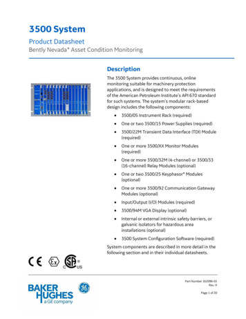
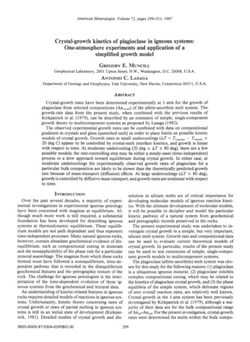
Overview 2 QUICKSTARTUpper Module BayPower Icon KeyIconDescriptionSetup Button:ExternalPower(USB)100%75%50%25%0%*Power RemainingLocate additional features: Clear Peaks Units (Adjust Available units)* Replace Batteries or connect to USB Power PM Mode: Gauge or Absolute Settings Contrast Lock/Unlock Chassis Summary Chassis, Upper, LowerNext button: RecordingProgress through the display screens Start/Stop Erase All RunsHome button:Brings you back to the default screen(Change Home Screen)LED Indication alerts::Flashes while recording(Flashes quickly when recording ends): Flashes when a module's range is exceededBacklight button:Turn on/off display backlight(Adjust Backlight Shutoff)Back button:Previous Display ScreenRecord button:Zero button:Press to zero Pressure Module reading (- - - - -)Start/Stop data recording(Adjust Logging Interval)Hold for 5 seconds to clear any zero value (- - -)(Adjust Zero Limit)Power button:Turn your nVision on/offNavigation & SelectLower Module BayThis icon represents a component that can be modified with CrystalControl softwarenVision Operation Manual
Functions 3Functions ON/OFFPower buttonPress and hold the ( power) button for 1 second to turn the nVision on or off. The nVision will automatically power down if not used for the time perioddefined in CrystalControl.Automatic Shutoff - Low Power ModeAdjust your Automatic Shutoff time (shut off time in absence of key press) to optimize battery life. This feature is adjustable from 30seconds to “always on.” During a recording, the nVision will enter Low Power Mode instead of shutting off.When powered by USB, the nVision does not employ any power management strategies. Therefore, it will not automatically shut off to the settings defined byCrystalControl.During a recording with a Logging Interval of 1 reading/minute or slower, your nVision will enter Ultra-Low Power Mode after the first reading elapses and theAutomatic Shutoff Timer runs out.The Backlight Shutoff is set separately in CrystalControl. It is unaffected by other settings. MEASUREMENTS & RECORDINGRecordingThe nVision can record at rates from 10 readings per second to 1 reading per hour as set in CrystalControl. Adjust your recording rate to optimize battery lifeand data recording space.Your nVision is capable of recording more than 500,000 data points when both module bays are populated. With one bay populated, thisnumber doubles. CrystalControl will give you a more accurate view of recording times based on the logging rate and enabled screens for your nVision.When connected to CrystalControl you can configure, control, and graph an nVision recording directly from your PC, without handling the nVision chassis.To start or stop a recording run from any screen:1 Press the (record) button for one second.Note:You may be prompted to enter a Run Tag, if enabled. For more information, see Run Tags.2 The red LED will start flashing when the recording begins.3 To stop recording, press the (record) button again. The red LED will flash twice.Note:The nVision records data for all screens enabled in Crystal Control. Even if you are viewing data for the lower module numerical display,data for the upper module will still record if any of the screens for that module are enabled. Use CrystalControl to check which data screens are enabled.nVision Operation Manual
Functions 4ZeroTo zero the nVision: Press the (zero) button for at least 1 second while vented to atmosphere until the dashed lines (- - - - -) appear.To clear the zero value: Hold the (zero) button for 5 seconds until the display changes from (- - - - -) to the zeroed value, then to (- - -).You can adjust the Zero Limit at which the (zero) button will display “- -HI- -” in CrystalControl. You can also disable the (zero) buttonentirely, by setting the zero value to a negative number less than -15 psi.Note: If you attempt to zero the gauge with more pressure applied than the Zero Limit set in with CrystalControl, the command will be ignored, and “- -HI- -”will display.Note: You can never zero the BARO sensor.!!WARNING: This gauge can display zero pressure when connected to a source of pressure! Do not rely on the display indication before disconnecting—it may not be indicating true pressure. Never disconnect pressure instrumentation without first relieving system pressure!nVision Operation Manual
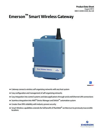
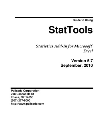
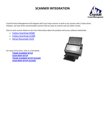
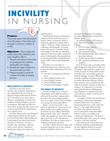
Functions 5 NUMERICAL DISPLAY OVERVIEWNumerical Upper and Lower Module screensHigh / Low:Peak always measuredat 10 readings persecondUpper Module ScreenData Point Counter ScreenDual Module ScreenData Point Screen (Single Sensor)Note:To change the displayed unitson any Numerical Display,see the Units section.Filter:Average of most recent20 readings/min:Rate of change perminuteNumerical Dual Mode Screen(Both Sensors)Lower Module ScreenVertical Scale:Applied versusfull-scale pressure(Pressure Module Only)Selectable Units (via Setup button)(Enable, disable, or create units)Sensor Reading biased towards applicablemodule location in the chassisDate & Time StampCurrent readingIndicates current data pointMaximum WorkingPressure:(Pressure Module Only) GRAPHICAL DISPLAY OVERVIEWGraphical Dual Mode Screen(Both Sensors)Graphical Upper and Lower Module screensUpper Module ScreenDual Module ScreenGraphical BARO Screen(Both Sensors)Dual Module ScreenNote:To change the displayed unitson any Graphical Display,see the Units section.Lower Module ScreenOn all graphical screensthe triple-arrow iconindicates the modulecurrently displayedDate and Time StampingFor safety, live readings aredisplayed regardless ofcursor location or zoom levelDate and TimeStampingLeft y-axis indicates the scale of thelower module. Right y-axis indicatesthe scale of the upper modulePressure module readingBARO module readingDisplays barometric pressure fromBARO module vs. output from onepressure module (Upper or Lower)nVision Operation Manual
Functions 6 GRAPHINGNavigating the Graphical DisplayIn the graphical modes the nVision navipad enables you to control how you view your data. The ( ) & ( ) keys allow you to navigate tospecific points along your run, while displaying reading and time information. The ( ) & ( ) keys allow you to zoom in and out of yourrecorded run to suit your needs.Panning Across the Data SetTo inspect the latest or current data recording, use the ( ) & ( ) keys to move the cursor within the display window. During live recording, data streamsfrom the right side of graphical display screens. Therefore, the most recent data will always appear on the far right of the display.Cursor locationLive recording areaZooming in on Specific DataTo see more detail on the latest or current data recording, you may zoom in or out on your cursor.1 Use the ( ) and ( ) arrows to zoom in or out in any graphical display, during or after recording.2 To return to the fully zoomed out view (viewing the complete run) simply hold the ( ) arrow for 5 seconds, or until you are completely zoomed out.Normal ViewZoom ViewDuring any zooming keystroke a zoomin ( ) or zoom out ( ) icon appearsWhen zoomed in, small arrows appear onthe horizontal time bar.nVision Operation Manual
Functions 7 AVERAGING MODEAveraging mode reports the average reading during the recorded run. If this screen is enabled, data displayed here represents the average of all past datapoints, over the duration of a recording. The start date and time, duration of the recorded run, and the live reading are displayed.nVision calculates averages as follows:r1 r2 r3 . rnnrn current readingn total number of readingsAveraging Mode DIFFERENTIAL MODEThe nVision automatically displays numerical and graphical differential screens if two similar module types are installed. ΔP becomes available if your nVisionis populated with two PM modules. ΔT becomes available if your nVision is populated with two RTD100 modules.In the case of the pressure modules (PM), this mode does not require them to be the same full scale range.!!WARNING: Two MA20 modules cannot be installed at once. This configuration may permanently damage your nVision.In Differential Mode the ΔP or ΔT represents a filtered reading of the upper module – lower module tare reading.Filtered live reading of upper moduleFiltered live reading of lower moduleTare value equalizes the upper and lower modulesDifferential ModeThe units selected for this view are independent of the units selected for the other screens such as the Numerical or Graphical views. Data viewed in theGraphical screens will represent the data acquired from either module and not represent the specialized view of the Differential Mode.Note: To change the displayed units on any Differential Display, see the Units section.nVision Oper
Crystal Engineering is the company that designs, manufactures, and services the nVision reference recorders, XP2i series pressure gauges, 30 series pressure . Averaging mode reports the average read