Transcription
2.0 Current-Carrying Capacity of BusbarsDavid Chapman & Professor Toby Norris2.1 Design PhilosophyThe current-carrying capacity of a busbar is limited by the maximum acceptable working temperature of the system, taking into account theproperties of the conductor material, the materials used for mounting the bars and the limitations of any cables (including their insulation) ordevices connected to the bars.There are two design limits; the maximum permitted temperature rise, as defined by switchgear standards, and the maximum temperature riseconsistent with lowest lifetime costs - in the vast majority of cases, the maximum temperature dictated by economic considerations will be ratherlower than that permitted by standards.National and international standards, such as British Standard BS 159 and American Standard ANSI C37.20, give maximum temperature risesas well as maximum ambient temperatures. For example, BS 159:1992 stipulates a maximum temperature rise of 50 C above a 24 hour meanambient temperature of up to 35 C, and a peak ambient temperature of 40 C. Alternatively, ANSI C37.20 permits a temperature rise of 65 C abovea maximum ambient of 40 C, provided that silver-plated (or acceptable alternative) bolted terminations are used. If not, a temperature rise of 30 Cis allowed.These upper temperature limits were chosen to limit the potential for surface oxidation of conductor materials and to reduce the mechanicalstress at joints due to cyclic temperature variations. In practice these limitations on temperature rise may be relaxed for copper busbars if suitableinsulation materials are used. A nominal rise of 60 C or more above an ambient of 40 C is allowed by EN 60439-1:1994 provided that suitableprecautions, such as plating, are taken. EN 60439-1:1994 states that the temperature rise of busbars and conductors is limited by the mechanicalstrength of the busbar material, the effect on adjacent equipment, the permissible temperature rise of insulating materials in contact with the barsand the effect on apparatus connected to the busbars. In practice, this last consideration limits the maximum working temperature to that of theinsulation of cables connected to the bar – typically 90 C or 70 C.Running busbars at a high working temperature allows the size of the bar to be minimised, saving material and initial cost. However, there aregood reasons to design for a lower working temperature. A higher maximum temperature implies a wider variation in temperature during the load cycle, which causes varying stress on joints andsupports as the bars expand and contract. Eventually, this may lead to poor joint performance and decreased reliability. In some cases it is difficult to remove heat from busbar compartments, resulting in ancillary equipment operating in an elevated ambienttemperature. High temperatures indicate high energy losses. Lowering the temperature by increasing the size of the conductor reduces energy lossesand thereby reduces the cost of ownership over the whole lifetime of the installation. If the installation is designed for lowest lifetimecost, the working temperature will be far below the limit set by standards and the system will be much more reliable.2.2 Calculation of Maximum Current-Carrying CapacityIn engineering terms, the current rating for a busbar depends on the choice of working temperature. The bar is heated by the power dissipated init by the load current flowing through the resistance, and cooled by radiation to its surroundings and convection from its surfaces. At the workingtemperature, the heat generation and loss mechanisms, which are highly temperature and shape dependent, are balanced.2.2.1 Methods of Heat LossThe heat generated in a busbar can only be dissipated in the following ways: Convection Radiation ConductionIn most cases, convection and radiation heat losses determine the current-carrying capacity of a busbar system. In a simple busbar, conductionplays no part since there is no heat flow along a bar of uniform temperature. Conduction need only be taken into account where a known amountof heat can flow into a heat sink outside the busbar system, or where adjacent parts of the system have differing cooling capacities. Conductionmay be important in panel enclosures.COPPER FOR BUSBARS 15
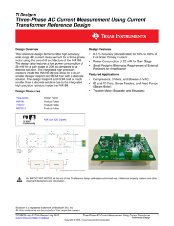
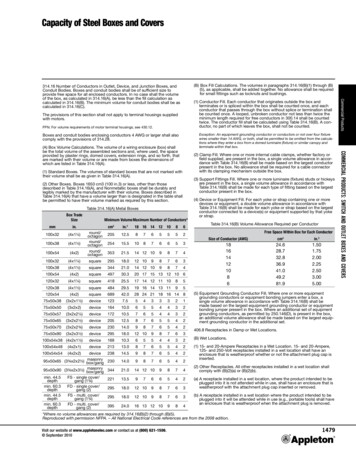
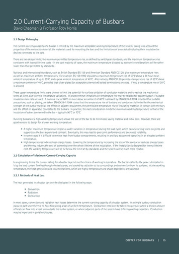
These cooling mechanisms are highly non-linear; doubling the width of a bar does not double the convection loss of a bar. The proportion of heatloss by convection and radiation depends on the conductor size, with the portion attributable to convection normally being greater for a smallconductor and less for larger conductors.2.2.1.1 Convection – Natural Air CoolingThe heat dissipated per unit area by convection depends on the shape and size of the conductor and its temperature rise above ambienttemperature. This value is usually calculated for still air conditions but can be increased greatly if there is forced air-cooling. Where outdoorbusbar systems are concerned, calculations should always be treated as in still (i.e. without wind effect) air unless specific information is given tothe contrary.The following formulae estimate the convection heat loss from a surface in W/m² in free air:For vertical surfaces:For horizontal surfaces:For round tubes:where:θ is temperature rise, CL is height or width of surface, mmd is diameter of tube, mm.Figure 4 shows the heat loss from a vertical surface (Wv) for various temperature rises plotted against surface height.Heat dissipation per square metre from a vertical surface (W/m2)80070060050030 degree C rise40 degree C rise50 degree C rise40060 degree C rise300200100050100150Surface height (mm)200250Figure 4 – Heat dissipation by convection from a vertical surface for various temperature rises above ambient16 COPPER FOR BUSBARS
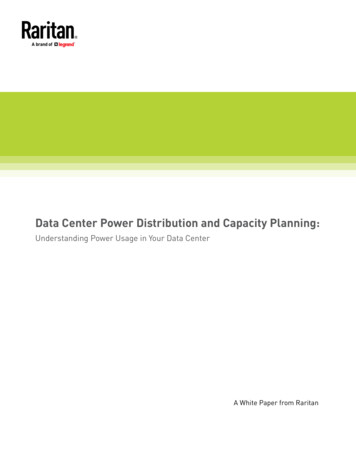
Figure 5 indicates which formula should be used for various conductor cWhWvWvWh(c)(d)Figure 5 - Convection loss from typical bar sectionsComparing diagrams (a) and (b) and assuming a similar cross-sectional area, it can be seen that the heat loss from arrangement (b) is much larger,provided the gap between the bars is not less than the thickness of each bar.2.2.1.2 Convection Heat Loss - Forced Air CoolingIf the air velocity over the busbar surface is less than 0.5 m/s, the above formulae for Wv, Wh and Wc apply. For higher air velocities the followingmay be used:where:WavAθis heat lost per unit length from bar, W/mis air velocity, m/sis surface area per unit length of bar, m²/mis temperature rise, C.COPPER FOR BUSBARS 17
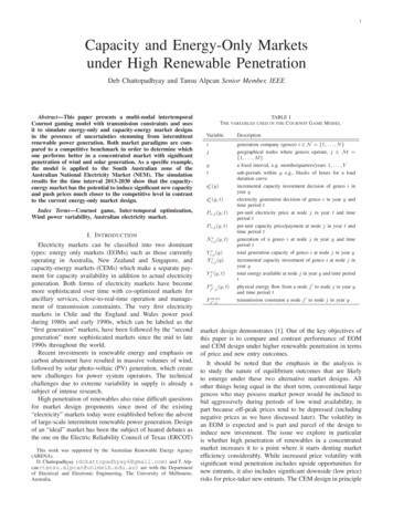
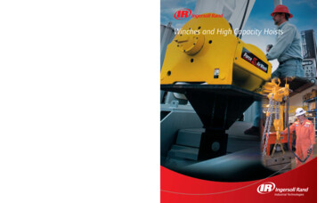
2.2.1.3 RadiationThe rate at which heat is radiated from a body to its surroundings is proportional to the difference between the fourth power of their absolutetemperatures and the relative emissivity between the body and its surroundings. Emissivity describes how well a material radiates heat with aperfect radiator (a black body) having a value of unity and a perfectly reflecting surface a value of zero.Since the amount of radiation depends on the temperature of the bar and its surroundings, bars in enclosed spaces may lose very little heat byradiation. Note that radiation in a particular direction will be influenced by the temperature and condition of any target surface.The relative emissivity is calculated as follows:where:e is relative emissivityε1 is absolute emissivity of body 1ε2 is absolute emissivity of body 2Typical emissivity values for copper busbars in various surface conditions are:Bright metalPartially oxidisedHeavily oxidisedDull non-metallic paint0.100.300.700.90The rate of heat loss by radiation from a bar (W/m²) is given by:where:e is relative emissivityT 1 is absolute temperature of body 1, KT 2 is absolute temperature of body 2, K (i.e. ambient temperature of the surroundings)350Heat dissipation by radiation (W/m2)300250200150100500203040506070Surface temperature above 30 degree ambient (C)8090100Figure 6 - Heat dissipation by radiation from a surface assuming relative emissivity of 0.5 and surroundings at 30ºC18 COPPER FOR BUSBARS
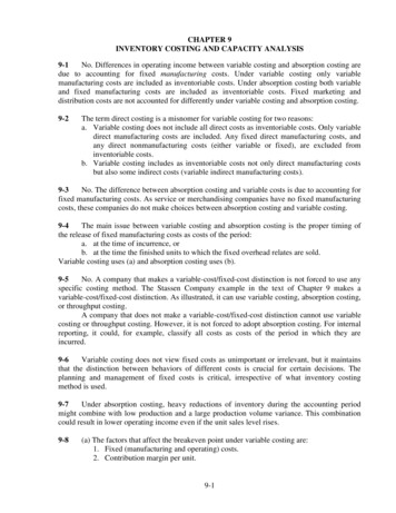
Figure 6 shows the heat loss from a surface against surface temperature. The diagrams in Figure 7 define the effective surface areas for radiationfrom conductors of common shapes and arrangements. Note that there is no heat loss by radiation from opposing busbar faces since thetemperatures are approximately d)Figure 7 - Radiation loss from typical bar sectionsThe ratio of heat dissipated by convection and radiation varies considerably according to the height of the surface and the temperature rise, withradiation becoming less important for smaller bars and lower temperature rises. Figure 8 combines the data from Figure 4 and Figure 6 with theradiation dissipation levels, which are independent of surface height, shown as horizontal bars on the right.In some countries it is common practice to attempt to increase emissivity to improve the dissipation by radiation by treating the surface ofbusbars, for example by painting them black. Since the natural emissivity of a copper bar that has been in use for even a short time will be above0.5 and probably approaching 0.7, the benefit of increasing it to 0.9, although positive, will be small. On the negative side, the paint layer acts asan insulator, reducing the efficiency of the convection process. In general, painting will give little increase and possibly a reduction in the currentcarrying capacity of a busbar for a given working temperature. Painting may be worthwhile for very wide bars (where convection is less effective)operating at large temperature rises (where radiation is more effective).COPPER FOR BUSBARS 19
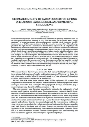
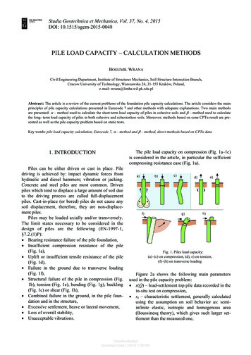
Heat dissipation per square metre from a vertical surface (W/m2)800700600Convection 60 degree C rise500Radiation 60 degree C riseConvection 50 degree C rise400Radiation 50 degree C riseConvection 40 degree C riseRadiation 40 degree C rise300Convection 30 degree C riseRadiation 30 degree C rise2001000050100150200250300350Surface height (mm)Figure 8 - Convection and radiation (right) losses at various temperaturesThe plots given so far have been in terms of power dissipated per unit area of surface; for engineering purposes it is the heat dissipation per unitlength which is of interest. Figure 9 and Figure 10 show the heat dissipation from the major surfaces of single and parallel vertically mounted bars.The relatively small contribution of the horizontal surfaces is ignored in these plots. These plots may be useful in determining a starting point fordetailed calculation using the formulae previously given.400Total heat dissipation per metre length (Watt)350300225 mm250200 mm175 mm200150 mm125 mm100 mm15075 mm50 mm1005002030405060Temperature rise above 30 degree ambient (C)7080Figure 9 - Total heat losses for a single bar of various heights against temperature rise20 COPPER FOR BUSBARS
400350Heat dissipation by radiation (W/m2)300225 mm250200 mm175 mm200150 mm125 mm100 mm15075 mm50 mm1005002030405060Surface temperature above 30 degree ambient (C)7080Figure 10 - Total heat losses for each bar of a parallel pair of various heights against temperature rise2.2.2 Heat Generated by a ConductorThe rate at which heat is generated per unit length of a conductor carrying a direct current is the product I²R watts, where I is the current flowingin the conductor and R is the resistance per unit length. In the case of dc busbar systems, the value for the resistance can be calculated directlyfrom the resistivity of the copper or copper alloy at the expected working temperature. Where an ac busbar system is concerned, the resistanceis increased because current density is increased near the outer surface of the conductor and reduced in the middle; this is called skin effect.Eddy currents induced by magnetic fields arising from currents in nearby conductors increase losses further; this is called proximity effect. Thecalculation of these effects is discussed later; for the present, a correction factor, S, is used.The power dissipated in the conductor iswhere:PIR0Sis the power dissipated per unit lengthis the current in conductoris the dc resistance per unit length at the working temperatureis the correction factor for shape and proximity.The process of sizing a busbar is one of iteration. Starting from an arbitrary size and the desired working temperature, the heat power loss fromthe surface of a one-metre section can be calculated. The electrical power loss for the one-metre section can also be calculated. If the electricalpower dissipated is higher than the heat dissipation, the bar is too small; the size should be increased and the calculations repeated until a closematch is obtained. Note that the value of resistivity used in the calculation must be corrected for the working temperature and the value of S (thecorrection for shape and proximity factors) must be recalculated for each size. A very approximate starting point is to assume an average currentdensity of 2 A/mm² in still air and iterate either up or down.COPPER FOR BUSBARS 21
2.2.2.1 Alternating Current Effects – the Factor SThe factor S, introduced above, is the product of the factors due to skin effect, Sk , and proximity factor, Sp . Accurate determination of skin andproximity effects is complex and generally requires finite element analysis. In this publication results are presented as curves and, where possible,‘portmanteau formulae’ in the form of polynomials or ratios of polynomials valid over a given range of an independent variable such as the scalingfactor, p, described below. Most of these formulae were found by curve fitting to data computed by finite element analysis. The portmanteauformulae do not always reflect satisfactorily a physical explanation and are usually very inaccurate outside the given range. They are normallyaccurate to within 1% within the stated range unless otherwise noted.The graphs are plotted from the computed data. To
The heat generated in a busbar can only be dissipated in the following ways: Convection Radiation Conduction In most cases, convection and radiation heat losses