Transcription
902HVAC Clamp MeterUsers ManualPN 2547887May 2006 Rev. 1, 3/07 2006-2007 Fluke Corporation. All rights reserved. Printed in China.All product names are trademarks of their respective companies.
LIMITED WARRANTY AND LIMITATION OF LIABILITYThis Fluke product will be free from defects in material andworkmanship for three years from the date of purchase.This warranty does not cover fuses, disposable batteries, ordamage from accident, neglect, misuse, alteration, contamination, or abnormal conditions of operation or handling.Resellers are not authorized to extend any other warrantyon Fluke’s behalf. To obtain service during the warrantyperiod, contact your nearest Fluke authorized service center to obtain return authorization information, then send theproduct to that Service Center with a description of theproblem.THIS WARRANTY IS YOUR ONLY REMEDY. NO OTHERWARRANTIES, SUCH AS FITNESS FOR A PARTICULARPURPOSE, ARE EXPRESSED OR IMPLIED. FLUKE ISNOT LIABLE FOR ANY SPECIAL, INDIRECT, INCIDENTAL OR CONSEQUENTIAL DAMAGES OR LOSSES,ARISING FROM ANY CAUSE OR THEORY. Since somestates or countries do not allow the exclusion or limitation ofan implied warranty or of incidental or consequential damages, this limitation of liability may not apply to you.Fluke CorporationP.O. Box 9090Everett, WA 98206-9090U.S.A.11/99Fluke Europe B.V.P.O. Box 11865602 BD EindhovenThe Netherlands
Table of ContentsTitlePageIntroduction.Contacting Fluke .Safety Information .Symbols .Getting Acquainted with the Meter .Using the Meter .AC and DC Voltage Measurement.Resistance and Continuity .Microamps µA Measurement .Temperature .Capacitance .AC Current Measurement .Backlight .MIN MAX Recording Mode .Display HOLD .Auto Off.Maintenance.Cleaning the Meter.Battery Replacement .Specifications .Electrical Specifications .General Specifications .i123561010111213161618181919202021232324
902Users Manualii
List of TablesTableTitlePage1. 902 HVAC Clamp Meter Features. 72. Display Features . 9List of FiguresFigure1.2.3.4.5.6.Title902 HVAC Clamp Meter Features.Display Features .Testing a Flame Rod .Temperature Measurement .Proper AC Current Measurement.Battery Replacement.iiiPage6813151722
902Users Manualiv
902IntroductionThe Fluke 902 is a hand-held battery-operated HVACClamp Meter (“the Meter”) that measures: AC current DC current (up to 200 µA for flame rod testing) AC and DC voltages Capacitance Resistance Continuity Temperature in both Celsius ( C) and Fahrenheit ( F)The Meter comes with: Two AA alkaline batteries (installed) Users Manual Soft carrying case TL75 Test Leads (one pair) 80BK Integrated DMM Temperature Probe1
902Users ManualContacting FlukeTo contact Fluke, call one of the following telephonenumbers:USA: 1-888-99-FLUKE (1-888-993-5853)Canada: 1-800-36-FLUKE (1-800-363-5853)Europe: 31 402-675-200Japan: 81-3-3434-0181Singapore: 65-738-5655Anywhere in the world: 1-425-446-5500Or visit Fluke’s Web site at: www.fluke.com.Register the Meter at: http://register.fluke.com2
HVAC Clamp MeterContacting FlukeSafety InformationA “XW Warning” statement defines hazardous conditionsand actions that could cause bodily harm or death.A “W Caution” statement identifies conditions and actionsthat could damage the Meter or the equipment under test.XWRead First: Safety InformationTo ensure safe operation and service of theMeter, follow these instructions: Read the Users Manual before use andfollow all safety instructions. Use the Meter only as specified in theUsers Manual; otherwise, the Meter'ssafety features may be impaired. Avoid working alone so assistance can berendered. Never use the Meter on a circuit withvoltages higher than 600 V or a frequencyhigher than 400 Hz fundamental. The Metermay be damaged. Never measure ac current while the testleads are inserted into the input jacks. Do not use the Meter or test leads if theylook damaged. Use extreme caution when working aroundbare conductors or bus bars. Contact withthe conductor could result in electricshock.3
902Users Manual4 Use caution when working with voltagesabove 60 V dc or 30 V ac rms or 42 V acpeak. Such voltages pose a shock hazard. Clean the case with a damp cloth and milddetergent only. Do not use abrasives orsolvents. To avoid false readings that can lead toelectrical shock and injury, replace thebatteries as soon as the low batteryindicator (B) appears. As the Meter getsto the point where the low batteries affectthe readings, the Meter locks and nomeasurements can be made until thebatteries are changed. Do not hold the Meter anywhere beyondthe tactile barrier, see Figure 1. Adhere to local and national safety codes.Individual protective equipment must beused to prevent shock and arc blast injurywhere hazardous live conductors areexposed.
HVAC Clamp MeterSymbolsSymbolsThe following symbols are found on the Meter or in thismanual.,May be used on hazardous live conductorsWRisk of danger. Important information. See UsersManual.XHazardous voltage. Risk of electric shock.TDouble insulationBBattery)Complies with Canadian and US StandardsPConforms to relevant European Union directivesJEarth groundFDC (Direct Current)BAC (Alternating Current) Do not dispose of this product as unsorted municipalwaste. Contact Fluke or a qualified recycler fordisposal.;N10140sConforms to relevant Australian standardsInspected and licensed by TÜV Product Services5
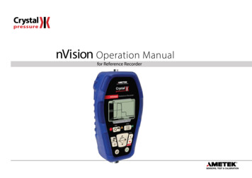
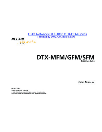
902Users ManualGetting Acquainted with the MeterRefer to Figures 1 and 2 and Tables 1 and 2 to becomemore acquainted with the Meter’s features.COMCAT600VµA Vefu0001.epsFigure 1. 902 HVAC Clamp Meter Features6
HVAC Clamp MeterGetting Acquainted with the MeterTable 1. 902 HVAC Clamp Meter FeaturesNumberDescriptionABacklight ButtonBJaw ReleaseCTactile BarrierDJawsEHold ButtonFRotary Switch:VDC and AC voltagePResistance and continuityGDC microampsFDegrees Fahrenheit / degrees CelsiusLCapacitanceKAC currentGLCDHMin Max ButtonIAC/DC, F/ C ButtonJInput Terminals7
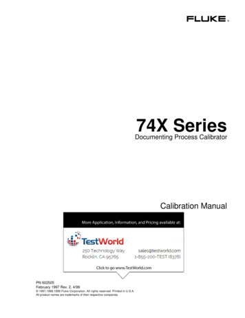
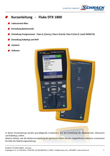
902Users ManualCDEFGBAefu0006.epsFigure 2. Display Features8
HVAC Clamp MeterGetting Acquainted with the MeterTable 2. Display FeaturesNumberIndicationBattery indicator -The batteries are low and need tobe changed. XWWarning: To avoid falseAreadings, which could lead to possibleelectric shock or personal injury, replacethe batteries as soon as the batteryindicator appears.BIndicates the presence of high voltageCIndicators for minimum and maximum recordingmodeDDisplay Hold is activeEVoltsFAmps F - Degrees Fahrenheit C - Degrees Celsiuse - OhmsGM - MicroampsN - MicrofaradsDC - Direct CurrentAC - Alternating Current9
902Users ManualUsing the MeterAC and DC Voltage MeasurementTo measure AC or DC voltage:1.Insert the test leads into the Meter.2.Turn the rotary switch to V.3.Press A to choose AC or DC voltage. The displayreflects the chosen voltage mode.4.Use the test leads to take the measurement. The Meterreading appears on the display.NoteWhen a measured voltage is above 30 V,Zappears on the display. When the voltage dropsbelow 30 V, Zdisappears.10
HVAC Clamp MeterUsing the MeterResistance and ContinuityTo measure resistance or continuity:XW WarningTo avoid false readings that can lead toelectrical shock and injury, de-energize thecircuit before taking the measurement.1.Insert the test leads into the Meter.2.Turn the rotary switch to P.3.Take the measurement. The resistance readingappears on the display. If the resistance is shorted, the Meter beeps andshows a reading 30 Ω. If the resistance is open or exceeds the Meter’srange, the display reads OL.11
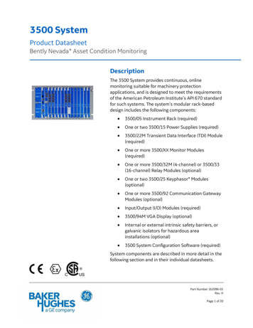
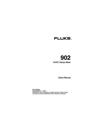
902Users ManualMicroamps µA MeasurementThe µA dc (G) function on the Meter is primarily for HVACflame rod testing. To test a heating system flame rod (referto Figure 3):1.Turn the heating unit off and locate the wire betweenthe gas-burner controller and the flame rod.2.Break this connection.3.Turn the rotary switch on the Meter to G.4.Using alligator clips, connect test leads between theflame sensor probe and control-module wire.5. Turn heating unit on and check the reading on theMeter.6. Refer to the heating unit documentation for what thedesired reading should be.12
HVAC Clamp MeterUsing the MeterBurnerefu0004.epsFigure 3. Testing a Flame RodTemperatureThe Meter measures temperature in either Celsius ( C) orFahrenheit ( F).To measure temperature (refer to Figure 4):13
902Users Manual1.Connect the 80BK Integrated DMM TemperatureProbe to the input jacks noting correct polarity of theprobe.2.Turn the rotary switch to F.3.Press A to select C or F. The display reflects thechosen temperature mode.4.Position the probe to take the measurement. Thereading appears on the display.NoteTo meet stated accuracy, the 80BK and Metermust be at the same temperature.XW WarningTo avoid possible electric shock DO NOT applythe probe tip to any conductor that is greaterthan 30 V ac, 42 V peak or 60 V dc to earth.14
HVAC Clamp MeterUsing the Meterefu0005.epsFigure 4. Temperature Measurement15
902Users ManualCapacitanceTurn off circuit power, then disconnect and discharge thecapacitor before measuring capacitance. Turn the Meter’srotary switch to capacitance (L).If the capacitor requires more discharging, diSC isdisplayed while the capacitor discharges. When measuring,be sure to note the correct polarity of the capacitor.AC Current MeasurementXW WarningTo avoid electrical shock and injury: Remove Test Leads before making currentmeasurements. Do not hold the Meter anywhere beyondthe tactile barrier, see Figure 1.Turn the rotary switch to AC current (K). When measuringAC current, it is necessary that the measured wire beproperly seated within the clamp jaws. The wire beingmeasured should be centered within the jaws, below thehorizontal line located on the clamp. Also note that currentsmoving in different directions will cancel each other out, soone wire must be measured at a time for a correctmeasurement (see Figure 5).16
HVAC Clamp MeterUsing the Meterefu0003.epsFigure 5. Proper AC Current Measurement17
902Users ManualBacklightPress C to toggle the backlight on and off. The backlightautomatically turns off after 2 minutes.To disable the automatic 2-minute backlight timeout, holddown Cwhile turning the Meter on.MIN MAX Recording ModeThe MIN MAX recording mode captures the minimum andmaximum input values. When a new high or low isdetected, the Meter beeps.To use this feature:1.Put the Meter into the desired measurement functionand range.2.Press Jto enter MIN MAX Mode. MAX is displayedand the highest reading detected since entering MINMAX is displayed.3.Press Jto step through the minimum (MIN) andpresent readings.4.To pause MIN MAX recording without erasing storedvalues, press I. K is displayed.5.To resume MIN MAX recording, press I again.6.To exit and erase stored readings, press Jfor atleast two seconds.18
HVAC Clamp MeterUsing the MeterDisplay HOLDXWWarningTo avoid possible electric shock or personalinjury, when Display HOLD is activated, beaware that the display will not change whenyou apply a different voltage.In the Display HOLD mode, the Meter freezes the display.The Meter also beeps every 4 seconds and Hflashesto remind the user.Press Ito activate Display HOLD; His displayed andthe reading is captured.To exit and return to normal operation, press I.Auto OffThe Meter automatically turns off after 20 minutes. Therotary switch must be turned to “OFF” and then turned backon for the Meter to restart. Auto Off is disabled during MinMax mode. To disable Auto Off, hold J when turningthe Meter on.19
902Users ManualMaintenanceXWWarningTo avoid possible electric shock or personalinjury, repairs or servicing not covered in thismanual should be performed only by qualifiedpersonnel.Cleaning the MeterXWWarningTo avoid electrical shock, remove any inputsignals before cleaning.W CautionTo avoid damaging the Meter, do not usearomatic hydrocarbons or chlorinated solventsfor cleaning. These solutions will react with theplastics used in the Meter.Clean the instrument case with a damp cloth and milddetergent.20
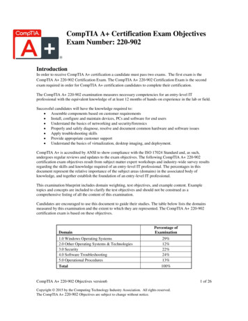
HVAC Clamp MeterMaintenanceBattery ReplacementXWWarningTo avoid false readings that could lead topossible electric shock or personal injury,replace the batteries as soon as the lowbattery indicator (B) appears.Disconnect the test leads before replacing thebatteries.To replace the batteries (refer to Figure 6):1.Turn the rotary switch to “OFF” and remove the testleads from the terminals.2.Use a Phillips screwdriver to loosen the batterycompartment door screw, and remove the door fromthe case bottom.3.Remove the batteries.4.Replace the batteries with two new AA batteries.5.Reattach the battery compartment door to the casebottom and tighten the screw.21
902Users Manualefu0002.epsFigure 6. Battery Replacement22
HVAC Clamp MeterSpecificationsSpecificationsElectrical ge DC0 – 600 V0.1 V1 % 5 countsVoltage AC(True Rms)0 – 600 V0.1 V1 % 5 counts(50/60 Hz)Current AC(True Rms)0 – 600 A0.1 A2.0 % 5 counts(50/60 Hz)Current DC0 - 200 µA0.1 µA1.0 % 5 countsResistance0 – 999 Ω0 – 9999 Ω0.1 Ω1.0 Ω1.5 % 5 countsContinuity 30 ΩTemperature -10 to 400 C0.1 C1 % 0.8 C1-100 µF100-1000 µF0.1 µF1 µF1.9 % 2 countsCapacitance23
902Users ManualGeneral SpecificationsOperating Temperature-10 C to 50 CStorage Temperature-40 C to 60 COperating HumidityNon condensing ( 10 C)90 % RH (10 C to 30 C)75 % RH (30 C to 40 C)45 % RH (40 C to 50 C)(Without Condensation)Operating Altitude2500 meters above mean sealevelStorage Altitude12,000 meters above meansea levelIP RatingIP 30 per IEC 60529Vibration RequirementsMIL-PRF-28800F Class 2random vibrationEMI, RFI, EMCEMI: instrument unspecified foruse in EMC field 0.5 V /MeterEMC: Meets all applicablerequirements in EN61326-1TemperatureCoefficients240.1 x (specified accuracy)/ C( 18 C or 28 C)
HVAC Clamp MeterSpecificationsSize (H X W X L)9.1 x 3.8 x 1.7 inches(240 x 80 x 40 mm)Weight1.1 lb(310 g)Design Standards andComplianceIEC 61010, IEC 61010-2032,CEAgency ApprovalsP ) ; sN10140Over-voltage CategoryPower Requirements600 V, CAT III per IEC 1010-1CAT III equipment is designedto protect against transients inequipment in fixed-equipmentinstallations, such asdistribution panels, feedersand short branch circuits, andlighting systems in largebuildings.Two AA Batteries, NEDA 15 A,IEC LR625
902Users Manual26
The Fluke 902 is a hand-held battery-operated HVAC Clamp Meter (“the Meter”) that measures: AC current DC current (up to 200 µA for flame rod testing) AC and DC voltages Capacit