Transcription
How do I?1Table of ContentsHow do I create a body? . 5Brief Introduction to bodies:. 5Steps to create a ground body . 5Steps to create a rigid body . 7Steps to create a flex body. 7Example model . 8Comments: . 9Additional info: . 9How do I create a beam? . 10Brief introduction to beams: . 10How to create beams using points . 10Example Model . 14Comments: . 15Additional info: . 15How do I create a Joint?. 16A brief introduction to joints: . 16How to create a joint . 17Ball. 17Fixed . 18Revolute . 19Translational . 20Cylindrical . 21Universal . 22Constant Velocity . 23Planar . 24Inline . 25Perpendicular . 26Parallel axes . 27Inplane . 28
How do I?2Orient . 29PTCV . 29CVCV . 30PTDCV. 31PTDSRF . 32How to review a joint:. 32Example Model . 33Comments: . 34Additional info: . 34How do I create a Motion? . 35Brief introduction to motion: . 35How to set up a MOTION load collector: . 35How to add grid point motion: . 36MOTNG . 36MOTNGC . 37MOTNGE . 38How to add joint motion:. 38MOTNJ. 38MOTNJC. 39MOTNJE . 39Example Model: . 40Comments: . 40Additional Info: . 40How do I create a Bushing? . 41Brief introduction to bushings . 41How to create a bushing . 41Example Model . 42Comments . 42Additional Info . 42Brief introduction to Analysis Methods . 43How to specify more than one Method of Analysis . 43
How do I?3Example Model . 45Comments . 45Additional info. 46How do I define Units?. 46Brief introduction to Units . 46How to define Units . 46Example model . 47Comments . 47Additional info. 47How do I create a Spring Damper? . 48Brief introduction to Spring Dampers . 48How to create a Spring Damper. 48Other Methods. 48Example Model . 50Comments . 51Additional info. 51How do I create a coupler? . 52Brief introduction to couplers. 52How to create a coupler. 52Example model . 53Comments . 53Additional info. 53How do I create a Marker? . 54Brief introduction to Markers . 54How to create a Marker . 54Example Model . 55Comments . 56Additional info. 56How do I create a curve?.57How do I create a Force or Moment? . 62
How do I?4Brief introduction to Forces and Moments . 62How to set up a load collector: . 63How to add grid point Force (MBFRC) . 64How to add grid point Force (MBFRCC) . 67How to add grid point Force (MBFRCE) . 69How to add grid point Moment (MBMNT) . 71How to add grid point Moment (MBMNTC) . 73How to add grid point Moment (MBMNTE) .75How do I create an Initial Condition? . 81Brief introduction to Initial Conditions . 81How to create an Initial Condition . 81Example model . 82Comments . 82Additional info. 82Bulk data input format . 83
How do I?5How do I create a body?Brief Introduction to bodies:Bodies are the model elements that have mass and inertia. Bodies can be of types: rigidor flexible. Rigid bodies are ideal representations of solid bodies or parts of fixed shapeand size. They are highly useful in simulations where deformation of a part is negligible. Arigid body has 6 DOF, and each rigid body added to a system adds an additional 6 DOF.Flexible bodies, or flex bodies, are used to model elastic deformation of bodies in asystem. The flex body connects to its neighboring elements and bodies through interfacenodes. The flex body consists of reduced stiffness and mass matrices, which can beobtained in various ways. The two methods used in HyperMesh are the Craig-Bamptonand Craig-Chang methods. Properties of a flex body are defined by the user inHyperMesh, and control the interaction of the flex body with other bodies.Steps to create a ground bodya. Click on the analysis radio button in the project browser, then click on the “bodies”button.b. Make sure that the radio buttons on the left are set to “create”. In the window next to“body ”, Give a name to the ground body.
How do I?6c. Click on the “type ” button, and select the option “GROUND”.d. At least one property, element, or node must be selected to create a body. To select aproperty, element, or node, click the corresponding yellow button, and a blue box willappear on the button. In the model display window, click on the entity you want to assignthe body to.e. Click “Create”.
How do I?7Steps to create a rigid bodyf. Follow steps a. and b. from creating a ground body.g. From the “type ” options, choose “PRBODY”.h. Choose the properties, elements, and nodes the same way as in part d. of creating theground body.i. Click “Create”.Steps to create a flex bodyj. Follow steps a. and b. from creating a ground body.k. From the “type ” options, choose “PFBODY”.a. Choose the properties, elements, and nodes the same way as in part d. of creating theground body.b. You may choose the Component Mode Synthesis method and frequency upper bound, orleave them as default. You must have values for at least the frequency upper bound orthe number of modes.c. Click “Create”.
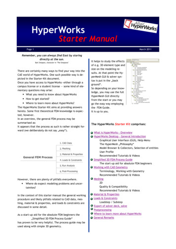
How do I?8Example trut CylinderStrut PistonHalf ShaftTie FlexGroundBulk Data UNDThis model of a MacPherson suspension uses rigid and flex bodies. Each component in thesystem is labeled in order to identify their properties, which can be found in the table. Theground body describes the reference environment, and does not add any degrees of freedomto the system and a flex body is used on the component of interest. Because this model is onlyfocused on the LCA characteristics under simulation, the other bodies in the mechanism arerigid.
How do I?9Comments:l. A maximum of 56 characters may be given for the body name.m. Flex H3D file name will be BODY NAME .h3d or OUTFILE body BID .h3d in the outfiledirectory.n. Any number of property definitions; CELAS2, CONM2, PLOTEL, RBAR, RBE2, RBE3 or RRODelements or grid points can be given.o. At least one property definition, element, or grid point must be given.p. A property definition; CELAS2, CONM2, PLOTEL, RBE2, RBE3, RBAR or RROD element orgrid point can only belong to one body (flexible or rigid).q. All property definitions, elements and grid points defined on a PFBODY or PRBODY bulkdata entry forms one flexible or rigid body respectively.r. CMS definition defines the component mode synthesis method to reduce the flexiblebody for the multi-body analysis. Exactly one must be defined for each PFBODY.s. Two methods are available for Component Mode Synthesis: CB – Craig-Bampton and CC –Craig-Chang.t. UB FREQ and NMODES cannot both be blank. When UB FREQ 0.0 and NMODES 0,this is a special case where no Eigen modes will be included in CMS mode generation.u. If FLXNODE is not defined, a default set of interface nodes and degrees-of-freedom will begenerated based on the actual interface nodes and degrees-of-freedom of the flexiblebody. One FLXNODE line can have up to six interface grid IDs. No continuation lines areallowed. Add multiple FLXNODE lines to add more than six interface nodes.v. The mass, inertia and center of gravity input is optional if element/property informationis provided in the PRBODY definition. If one of MASS, INERTIA or COG continuations isprovided, all three continuations must be provided. MASS must be positive non-zerovalues. If just the principal inertia is specified, IXX, IYY, IZZ must be positive non-zerovalues and they must satisfy the condition: the sum of two inertia values must be greaterthan the third (IXX IYY IZZ, IYY IZZ IXX, IZZ IXX IYY).w. For a PRBODY, a CID of zero or blank references the basic coordinate system.x. The grid ID provided in the ground card is considered grounded.y. These cards are represented as a group in HyperMesh.Additional info:z. ers/body lp/hwsolvers/body rigid lp/hwsolvers/body flexible.htmaa. iles/Altair/11.0/help/hwsolvers/pfbody.htm
How do I?10How do I create a beam?Brief introduction to beams:A beam is an entity defined as a straight, mass less beam of uniform cross section actingbetween two points or markers belonging to two different bodies. The mass of the beam islumped at each point. Beam stiffness properties are derived using Timoshenko beam theory.The beam axis is assumed to be along the x-axis of the Body 2 Reference Marker. This markeraxis also represents the neutral axis of the un-deformed beam. The beam is assumed to undergosmall rotational deflections; large rotations are not supported.How to create beams using pointsa. In the project menu, click on the 1D radio button, then click the “HyperBeam” button.b. Leave the settings as “Standard Selection”, library: “HYPERBEAM”, and type: “thinwalled box”, then click “create”. This will bring you to the HyperBeam workspaceenvironment.c. In the Parameter Definition window in the lower left corner of the window, change thevalues of dimensions a and b, as well as the thickness, to the desired values.d. In the browser menu at the top of the window, click File Exit.
How do I?11e. Create a new property by right clicking in the Model tree, and selectingCreate Properties.f.Give the property a name, and set the card image to PBEAM.g. Assign a material to the property in the material tab, and make sure the card edit box ischecked before clicking “Create”.
How do I?12h. This will bring up the card edit panel for PBEAM. Click the yellow button labeled“beamsec”.i.In the selection panel, choose the newly created beam.j. Hit return to exit the card edit panel.k. In the project menu, select the 1D radio button, then click on the “bars” button.l.Set the orientation to “vector”, and switch the value next to it to “x-axis”.m. Click the “property ” button and select the property that was just created.n. Click the “elem types ” button and select the “CMBEAM” card.o. The first of the two yellow boxes will automatically be checked. Click on the first node tobe connected in the model window. After this, the second yellow box will already beselected. Click on the second node to connect.
How do I?13p. This will create a beam between the two nodes.q. Click “return” to go back to the project menu.To create a beam using markers, a bulk data card must be used. Begin by clicking on the “controlcards” button in the analysis panel of the Project Menu.Click on the “BULK UNSUPPORTED CARDS” button to open the Control Card window.Define the beam in the control card using the following format:
How do I?14Where EID is the element ID of the beam, MID is the Material identification number, M1 and M2are Marker identification numbers, L is the Undeformed Length of the beam, A is the Crosssectional area of the beam, I1 is the area moment of inertia in plane 1 about the neutral axis, I2is the area moment of inertia in plane 2 about the neutral axis, J is the torsional constant, and K1and K2 are the Area Factors for Shear. An example is shown here:Click “ok” to close the Control Cards window, and the beam will automatically be created. Click“return” to go back to the Project Menu.Example Modelbeam start.hmThis model consists of two point mass bodies, using predefined components, materials, and properties,in order to simplify the process of adding a beam between two nodes.
How do I?15Comments:r.Element identification numbers must be unique with respect to all other elementidentification numbers.s. The x-axis of the beam is always along the line connecting G1 and G2. The z-axis of thebeam is determined based on the x-axis and the y-axis provided by G3/X1, Y1, Z1.t. Only MAT1 material definitions may be referenced by the CMBEAM element.u. This card is represented as a bar2 element in HyperMesh.Additional am%20Files/Altair/11.0/help/hwsolvers/beam elements guidelines.htm
How do I?16How do I create a Joint?A brief introduction to joints:A joint or constraint is a mechanical connection which constrains relative motion betweenbodies. They are also used to restrict the motion of bodies independently. There are a numberof joints that can be used to do this and the joint may restrict the absolute motion of a bodyrelative to the ground body or the relative motion between interconnected bodies. InMotionView you can create 17 types of Joints. These 17 joints fall into three separatecategories: Lower Pair Constraints, Higher Pair Constraints, and Joint Primitives.A Lower Pair Constraint is an ideal joint that constrains contact between a point, line or plane inthe moving body to a corresponding point, line or plane in a fixed body or another moving body.In Higher pair constraints, the two bodies are in contact at a point or along a line, as in a ballbearing or disk cam and follower and the relative motions of coincident points are not same.A joint primitive places a restriction on relative motion, such as restricting one part to alwaysmove parallel to another part. The joint primitives do not have physical counterparts as theidealized joints do. You can, however, combine joint primitives to define a complex constraintthat cannot be modeled using the idealized joints.The joints used by HyperMesh, as well as their DOF constraints can be seen in the table below:Constraint TypeTranslational ConstraintsRotational ConstraintsTotal ConstraintsConstant 325Translational235Spherical / 01Perpendicular Axes011Parallel Axes022Point to Deformable Surface1Point to Curve2Curve to Curve3Point to Deformable Curve2
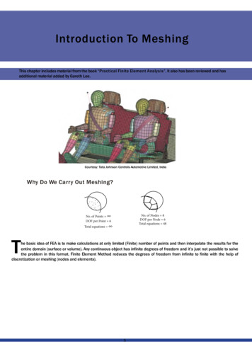
How do I?17How to create a jointThe following instructions on creating joints are organized in order of their occurrence inHyperMesh.balluniversalparallel axesptdcvfixedconstant nlineptcvcylindricalperpendicularcvcvBallFigure 15: A ball jointA Ball Joint (also known as Spherical joint) is a three degree of freedom kinematic pair used inmechanisms. Spherical Joints provide three-axes rotational function used in many places such asball and socket joints, pivots between wheels and suspension of an automobile, and motioncontrol systems.i. Begin by opening the Joints panel in the 1D Project Menu.ii. For “joint type:” select ball from the joints list.
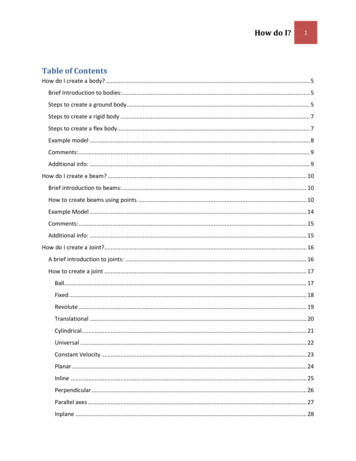
How do I?18iii. A ball joint requires two elements from separate bodies to be selected. Use themodel window to click on the elements needed, or specify them by id by clickingon the “node” button that is already highlighted.iv. After selecting both nodes, click the “create” button on the right, and “return”to go back to the project menu.(return to Joints)FixedFigure 4: A schematic of a FIXED jointA Fixed Joint is a zero degree of freedom kinematic pair used in mechanisms. Fixed Joints doesnot provide any degree of freedom, and used in many places such as welded joints or rivetedjoints.v. Begin by opening the Joints panel in the 1D Project Menu.vi. For “joint type:” select fixed from the joints list.
How do I?19vii. A fixed joint requires nodes from two separate bodies. Use the model windowto click on the elements needed, or specify them by id by clicking on the “node”button that is already highlighted.viii. After selecting both nodes, click the “create” button on the right, and “return”to go back to the project menu.(return to Joints)RevoluteFigure 13: A revolute jointA Revolute Joint (also known as a pin joint or a hinge joint) is a one degree of freedom kinematicpair used in mechanisms. Revolute joints provide single-axis rotation function used in manyplaces such as door hinges, folding mechanisms, and other uni-axial rotation devices.ix. Begin by opening the Joints panel in the 1D Project Menu.x. For “joint type:” select revolute from the joints list.xi. A revolute joint attaches two bodies and constrains 5 DOF. Entities from twodifferent bodies are required, as well as an orientation for the axis of rotation.This can be done by choosing either a node or a vector; this can be specified byclicking the arrow next to the yellow “node” button.
How do I?20xii. After selecting both nodes and the orientation, click the “create” button on theright, and “return” to go back to the project menu.(return to Joints)TranslationalFigure 16: A translational jointA Translational joint (also known as Prismatic Joint) provides a linear sliding movement betweentwo bodies. It allows one degree of freedom in the joint. The relative position of two bodiesconnected by a prismatic joint is defined by the amount of linear slide of one relative to theother one. Trans
q. lick return _ to go back to the project menu. To create a beam using markers, a bulk data card must be used. egin by clicking on the control cards button in the analysis panel of the Project Menu. lick on the ULK_UNSUPPORTED_ARDS button to open the ontrol ard window. Define the beam in the control card using the following format: