Transcription
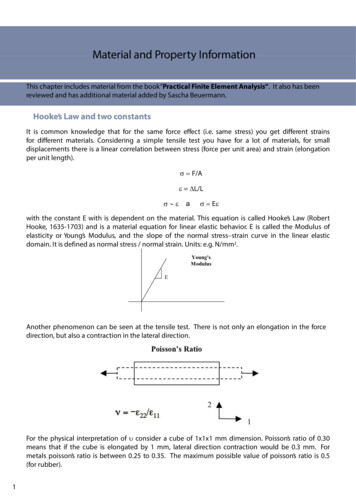
Material and Property InformationThis chapter includes material from the book“Practical Finite Element Analysis”. It also has beenreviewed and has additional material added by Sascha Beuermann.Hooke’s Law and two constantsIt is common knowledge that for the same force effect (i.e. same stress) you get different strainsfor different materials. Considering a simple tensile test you have for a lot of materials, for smalldisplacements there is a linear correlation between stress (force per unit area) and strain (elongationper unit length). F/A L/L a E with the constant E with is dependent on the material. This equation is called Hooke’s Law (RobertHooke, 1635-1703) and is a material equation forf linear elastic behavior. E is called the Modulus offelasticity or Young’s Modulus, and the slope of the normal stress–strain curve in the linear elasticdomain. It is defined as normal stress / normal strain. Units: e.g. N/mm2.Young'sModulusEAnother phenomenon can be seen at the tensile test. There is not only an elongation in the forcedirection but also a contraction in the lateral direction.direction,directionFor the physical interpretation of consider a cube of 1x1x1 mm dimension. Poisson’s ratio of 0.30means that if the cube is elongated by 1 mm,mm lateral direction contraction would be 0.30 3 mm.mm Formetals poisson’s ratio is between 0.25 to 0.35. The maximum possible value of poisson’s ratio is 0.5(for rubber).1
There is also the material parameter G Modulus of rigidity, which is the slope of the shear stress-straincurve in the linear elastic domain. It is defined as shear stress/shear strain. Units: e.g. N/mm2E,, G,, and are inter-related byy the equation:qE 2 G (1 )Only two independent material constants are required for a linear static analysis (i.e. E, and ).Additional data is required for gravity, centrifugal load, and dynamic analysis (material density m/V, mass per unit volume e.g. g/cm3) and for temperature induced stresses or strains (coefficient ofthermal expansionp T l l T, expansion/shrinkagepg pper unit lengthg pper temperaturepe.g.g 1/K).For steel, 7.89 10-9 t/mm3 and 1.2 10-5 1/K, and for aluminum, 2.7 10-9 t/mm3 and 2.4 10-5 1/K.2. Generalized Hooke’s law and 36 total constants in the equationHookess law is familiar to us as σ E * ε (see Section 3.1).Hooke’3 1) This equation holds true for isotropic materialthat is in the linear elastic domain. The general equation of Hooks law for an anisotropic material is:σxx E11 εxx E12 εyy E13 εzz E14 γxy E15 γyz E16 γzxσyy E21 εxx E22 εyy E23 εzz E24 γxy E25 γyz E26 γzxσzz E31 εxx E32 εyy E33 εzz E34 γxy E35 γyz E36 γzxτxy E41 εxx E42 εyy E43 εzz E44 γxy E45 γyz E46 γzxτyz E51 εxx E52 εyy E53 εzz E54 γxy E55 γyz E56 γzxτzx E61 εxx E62 εyy E63 εzz E64 γxy E65 γyz E66 γzxThere are a total of 36 constants (E11, E12, ,EE66) out of which 21 are independent.independent3.Material ClassificationIsotropicIso – same,sameTropic - directionsOrtho – three,threeTropic - directions Propertiesindependent ofdirection/axes 2 IndependentConstants (E, υ) Metals 2Orthotropic AnisotropicDifferentproperties alongcrystallographicplaneDifferentproperties along3 axes 21 independentconstants9 independentconstants All real lifei l arematerialsanisotropiconly but wesimplify themin to categoryof Isotropic andOrthotropicWood, Concrete,rolled metalsLaminates Two or morematerials bondedtogether in layers. Simplest exampleis laminationcarried out oncertificates,Identity cards etc. Mainly used forspace applicationsand these days inautomobiles thetrend is shiftingtowards plasticsand laminatesffrommetals.t l
Material PropertiesPoisson’s .10 1050.30Cast Iron1.20 105Wrought Iron7.89 4200.287.20 10-9852201.90 1050.307.75 10-9210320Aluminium0 70 1050.700 350.352 70 10-992.703590Aluminium alloy0.75 1050.332.79 10-9165260Brass1.10 1050.348.61 10-995280Bronze1.20 1050.348.89 10-9105210Copper1.20 1050.349.10 10-970240Copper alloy1 25 1051.250 330.339 75 10-999.75150400Magnesium0.45 1050.351.75 10-970160Titanium1.10 1050.334.60 10-9120300Glass0.60 1050.222.50 10-9--100Rubber500.490.92 10-9410CConcretet0 25 1050.250 150.152 10 10-992.10--40Material* Above listed properties are approximate and properties as per actual material composition are recommended.Why mass is in tonne and density tonne /mm3 for N-mm unit system?1 N 1 kg 1 m / s2(F m*a)a 1 N 1000 kg 1 mm / s2a1 N 1 kg * 1000 mm/s2a1 N 1 tonne 1 mm/s2Hence when force is specified in N, length in mm, mass must be specified in tonne anddensity in tonne /mm3Examples of sets of consistent units (see Chapter II) for steel are:Length unitmeterSystem mmt-smillimeterMass unitkilogramtonnekilogramTime unitsecondsecondmillisecondForce 10.0e 09210.0e 03210.07.85e 037.95e-097.98e-06Poisson’s Ratio0.30.30.3SI-systemSIsystem3Systemmm- kgmsmillimeter
5. Material and Property Tutorials and Interactive VideosTo view the following videos and tutorials, you first need to register at the HyperWorks Client Centerusing your university E-Mail address. Once you have a password, log into the Client Center and thenaccess the videos and tutorials using the links below.Recommended VideosInteractive Videos (10-15 minutes; no HyperWorksypinstallation required)q Material Definition Property Definition Assign Property to ElementsW biWebinars Simulation Accuracy (Material & Rupture Libraries) with RADIOSS How to solve plan strain problems in Nastran (OptiStruct) - by Prof. J. Chessa, Texas Seeing Steel in a New LightPDF4
Student Racing Car Project - Material DefinitionThe frame will be built out of steel with the following properties: linear elastic, isotropic andtemperature independent, which corresponds to the definition of MAT1 (Card image).Units are: N, mm2 and t (tons)Frame property definition & trouble shootingFor simplicity reasons the frame will be modeled with CBAR elements referencing a“tube”crosssection with constant properties. The CBAR element properties can be best created with HyperBeam(integrated in HyperMesh). Once the cross section is defined, the cross section information is thenstored as a beamsection within a beamsection collector.The workflow is as:o Define the required tube cross-section with HyperBeam and store the respective cross sectiondata (area, moment of inertia etc.) in a beamsection collectoroGenerate a property collector with Card Image PBARL. Inside this property collector thepreviously defined beamsection and a material collector is referenced.referenced Eventually,Eventually the propertycollector is then assigned to all CBAR elementsThese steps are explained in some detail next:I. Defining the tube cross-section with HyperBeamHyperBeam can be accessed through the menu bar by selecting Properties HyperBeam.5
Note: As we are using OptiStruct (Radioss bulk) as FEM solver, our lives become easier if we makeuse of the 1D section library of OptiStruct. Therefore, the standard section library should beOPTISTRUCT, the standard section type should be Tube. Other section do exist of course.In the graphic editor of HyperBeam, the chosen tube section is displayed.For the base design (it is actually just a“guess”) the tubes radii are assumed to be :rout 12.5 mm, rinside 10.5 mm.Of course, the tubes inner (DIM2) and outer (DIM1) radii can be easily changed and adjusted inHyperBeam.Based on the cross-section, values such as area, moments of inertia etc. are automaticallydetermined and listed in the side bar of HyperBeam. All this information is now readily available as abeamsection stored in a beamsection collector (Note, that different beamsections with differentattributes, names and ID’s may reside inside a beamsection collector).6
Once the definition of the cross section is completed you can return to the HyperMesh GUI byclicking the iconII.within the Model Browser.Defining a property collectorAs before with the material collector, make a right mouse button click in the Model Browser andspecify the Card Image PBARL as well as the previously defined material.The Card image of the property collector (PBRL) includes references to: Beamsection (here the ID of the beamsection is 8) of cross section type (CStype) TUBE.Inner and outer radii are DIM2 and DIM1 Material (MID 1)IIn theth nextt step,t thisthi propertyt collectorll t isi assignedid tot theth 1D elements.lt Hereto,H t theth respectivetifunctionality available in the Model Browser is used (right mouse button click on the property andselect Assign).To better visualize the 1D elements, we switch from the Traditional Element Representationto 3D Element Representation240. In addition the element shrink optionis activated.
Figure: Car frame meshed with 1D elements (CBARS) with shrink viewon. The x-symbolsoutside the frame refer to geometry points. These points will be used to model the wheelpsuspension.Figure: Detailed view of the meshed frame (shrink view mode is active). A uniform tube cross sectionis used for simplicity reasons (ro 12.5 mm, ri 10.5 mm).Trouble shootingHowever, it may happen that some 1D elements are not properly displayed. What is the problem?8
In theh figurefabove,btheh depicteddd linel is actuallyll a CBAR element.lLikely causes and ways to solve this issue:1. Make sure that a“property”is assigned to ALL the 1D elements. This can be checked visually inmany ways, for instance, by activating the element display mode:2.3.If a property collector is assigned to the 1D elements, they will be displayed with the same coloras the property collector.Check the properties of the 1D elements again i.e. review the property collector (in the ModelBrowser make a right mouse button click on the corresponding property collector and selectCard Edit).Edit)Check the element orientation.The element orientation is defined through its local xy-plane. The local element xy-plane in turnis defined through its x-axis (longitudinal direction from node a to b) and a vector v. Basically,one needs to take care of the v vector in order to solve (determine) the element orientation!(more information is also available in the help documentation lvers htmthen Index CBEAM or CBAR)To control (or update) the local element xy-plane and thus the v vector go to the Bars panel byselecting Mesh Edit 1D Elements Bars Update from the menu bar.Select any of the displayed 1D elements (in the image the 3D Element Representationactive).9is
As shown above this will display not only the local element coordinate system but also thecomponents of the vector v (with respect to the global coordinate system). Here, the vector vparallels the global y-direction(y comp 1). The element xy-plane thus parallels the global xy-plane.In the next step, we are reviewing the element orientation of a 1D element which is not properlydisplayed (cross-sections are not shown).Just repeat the“review steps”from before:This time the location of node a and b is shown only. In the panel shown below it becomes apparent10
that the components of the v vector are all zero.The good thing: the components of vector v can be corrected/updated at any time.Select a single or all elements, then specify the component of the vector v with respect to the global(basic) coordinate system. In case the y-component of vector v is set to y 1 (global y), both, vector vand local y-direction of the element coincide. In the image below the local y direction and v vectorare superimposed on each other.In the image below, the vector v doesn’t coincide with any of the global components. Now it is quiteapparent, that vector v and local x-axis together specify the local xy-plane of the element.11
The same element is viewed from a different direction12
This chapter includes material from the book“ Practical Finite Element Analysis”. It also has been reviewed and has additional mate rial added by Sascha Beuermann. Hooke’sLawandtwoconstants It is common knowledge that for the same force effect (i.e. same s