Transcription
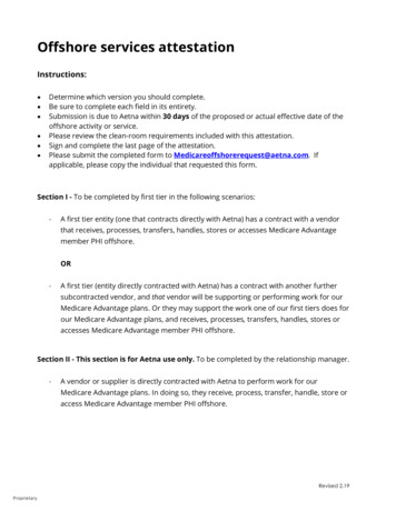
Predicting Offshore Topside Wind LoadingUsing AcuSolveAbdel Fiala – CFD Technical SpecialistSeptember 2nd, 2014
Copyright 2014 Altair Engineering, Inc. Proprietary and Confidential. All rights reserved.Content Objective Geometry Modelling conditions CFD models Results and analysis Conclusion
Copyright 2014 Altair Engineering, Inc. Proprietary and Confidential. All rights reserved.Objective To demonstrate the utility of CFD using AcuSolve in improving theprediction of wind loading on typical large offshore platform topside Current wind loading assessment is based on semi-empirical methods,nowadays widely used in the offshore industry. These tend to overestimate wind loading on the topside structure This translates in to large safety factors and over-design of thestructural components sustaining the stresses due to wind loading CFD simulation aims at reducing or disposing off this over-prediction No experimental data are available. Hence, comparison is made againstthe semi-empirical data available. A thorough investigation of CFD modelling/simulation parameters, suchas mesh size, unsteadiness, timestep size, and turbulence modelling, isconducted to increase the reliability of the results obtained.
Copyright 2014 Altair Engineering, Inc. Proprietary and Confidential. All rights reserved.Digression: Validation of AcuSolveJFE-2011 “Detached Eddy Simulation of Atmospheric Flow About aSurfaceMounted Cube at High Reynolds Number”
Copyright 2014 Altair Engineering, Inc. Proprietary and Confidential. All rights reserved.Digression: Airflow around a building (JJ Tower)
Acusolve: CFD simulation is performed to evaluate the positioning of the JJtower in the city.
Copyright 2012 Altair Engineering, Inc. Proprietary and Confidential. All rights reserved.AcuSolve for External Air Flow – Terrain
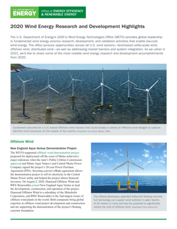
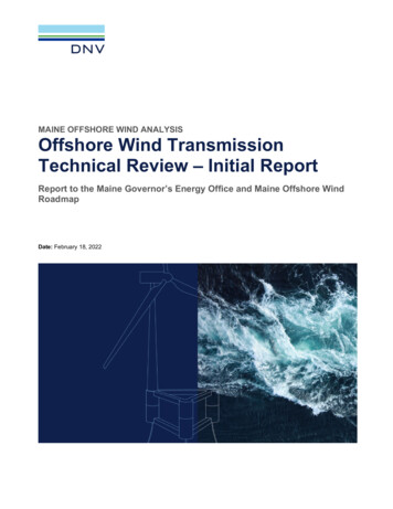
Copyright 2014 Altair Engineering, Inc. Proprietary and Confidential. All rights reserved.Geometry Model consists of an assembly of rectangular blocks of 14 x 30 x 10 m3in x, y, z respectively Maximum size is 70 x 60 x 40 m3 in x, y, z respectively. Reference elevation 25mM26M16M06M31M21M13 M14M12M11M04 M05M03M01 M02
Copyright 2014 Altair Engineering, Inc. Proprietary and Confidential. All rights reserved.CFD Geometry Model elevation 25m above sea level External domain 1120 x 660 x 465 m3 Sea is considered a flat wall (no waves) No sea current; Vsea 0 Wind directions investigated: X, Y, XY,and -X.
Copyright 2014 Altair Engineering, Inc. Proprietary and Confidential. All rights reserved.Modelling Conditions Wind loading is based on 1-hour mean wind speed for the topside model This is initially applied on the model in the X direction for the CFDmodelling investigation Thereafter, it is applied in the Y, XY (45deg) and –X directions. No data on freestream turbulenceare available A freestream turbulence viscosityratio (VR) of 10 is used for the mainCFD modelling investigations Effect of freestream turbulence isassessed; VR between 10 and 1e6
Copyright 2014 Altair Engineering, Inc. Proprietary and Confidential. All rights reserved.CFD Models Due to the lack of experimental data to compare directly to, an in-depthinvestigation of CFD methodology is conducted; wind in X direction: Mesh size dependency Steady-state vs transient. The latter using Unsteady RANS turbulence model Timestep size dependency for transientM26 Turbulence modellingM21o Freestream turbulence levelM16o Transient URANS vs DES turbulenceM06 RANS: Spalart-Allmaras modelM31M13 M14M11 M12M03 M04 M05M02M01 DES: Delayed DES based on Spalart et al. (2006) Results are compared against data based on semi-empirical methods45degs ve Y-axisWind load (MN)Total base shear along Y-axis (MN)Total base shear along X-axis (MN)Total base shear @ 45degs (MN) ve X-axis ve ve Y-axis ve X-axiswinward leeward winward leeward winward leeward winward leeward6.2558.7088.041
Copyright 2014 Altair Engineering, Inc. Proprietary and Confidential. All rights reserved.1. Effects of CFD modeling parameters
Copyright 2014 Altair Engineering, Inc. Proprietary and Confidential. All rights reserved.Transient Time Step Size Effects An initial mid mesh size, without edge refinement, was used for thisspecific exerciseNumber ofElements(million)Max SurfaceElement Size(m)b.l. FirstLayer Height(mm)14.11.04.0 Very little effect on wind loadingand Y-moment, with 1% difference.Timestep Size, Δt(ms)Wind Load(MN)Moment about Y-axis(MN.m)Coarse (Run 03)50.06.333276.4Mid (Run 04)25.06.339276.1Fine (Run 05)12.56.351277.4Largest difference-0.0181.30.3%0.5%Largest difference
Copyright 2014 Altair Engineering, Inc. Proprietary and Confidential. All rights reserved.Transient Time Step Size Effects All transient solutions converge towards steady-statezoomzoom
Copyright 2014 Altair Engineering, Inc. Proprietary and Confidential. All rights reserved.Mesh Size EffectsSteady-StateNumber ofElements(million)Max SurfaceElement Size(m)b.l. FirstLayer Height(mm)Wind Load(MN)Momentabout Y-axis(MN.m)Coarse (Run11)8.22.08.06.397276.6Mid (Run 09)27.91.04.06.459280.2Fine (Run 10)119.20.52.06.501282.5 Coarse to fine---1.6%2.1% The solution shows very little sensitivity to mesh size in bothsteady-state and transient modes.Transient(Δt 25ms)Number ofElements(million)Max SurfaceElement Size(m)b.l. FirstLayer Height(mm)Wind Load(MN)Momentabout Y-axis(MN.m)Coarse (Run13)8.22.08.06.408277.3Mid (Run06)27.91.04.06.454280.0Fine (Run 07)119.20.52.06.482281.7 Coarse to fine---1.2%1.6%
Copyright 2014 Altair Engineering, Inc. Proprietary and Confidential. All rights reserved.Mesh Size Effects – Solution HistorySteady-stateTransient Δt 25ms
Copyright 2014 Altair Engineering, Inc. Proprietary and Confidential. All rights reserved.Mesh Size Effects (Coarse)
Copyright 2014 Altair Engineering, Inc. Proprietary and Confidential. All rights reserved.Mesh Size Effects (Mid)
Copyright 2014 Altair Engineering, Inc. Proprietary and Confidential. All rights reserved.Mesh Size Effects (Fine)
Copyright 2014 Altair Engineering, Inc. Proprietary and Confidential. All rights reserved.Mesh Size Effects – Pressure/Streak-lines Very similar surface pressure distributions with some small differencesin surface streak-lines; separation and reattachment lines.
Copyright 2014 Altair Engineering, Inc. Proprietary and Confidential. All rights reserved.Mesh Size Effects – Velocity Field Separation right off the corners of the windward face Large wake Wind loading mainly consists of “form” drag.
Copyright 2014 Altair Engineering, Inc. Proprietary and Confidential. All rights reserved.Mesh Size Effects – PerformanceNumber of Elements (million)Number of Nodes (million)Meshing CPU (min)Meshing Memory ine119.2520.1123.236495 Meshing on desktop with Intel i7-4820K quad core CPU @ 3.7GHzSteady-StateRunning CPU(sec)CoresRunning CPU(hour)TimestepsPhysical Time(sec)Coarse (Run 11)2196160.6147-Mid (Run 09)4855641.3556-Fine (Run 10)30854648.5765-Coarse (Run 13)2011101655.9280070Mid (Run 06)1544876442.9280070Fine (Run 07)33586412893.3280070Transient(Δt 25ms) Running on cluster of Intel Xeon Processor E5-2670 (8-core 20M Cache 2.60 GHz)
Copyright 2014 Altair Engineering, Inc. Proprietary and Confidential. All rights reserved.Transient vs Steady-State Very little difference is seen between the steady-state and transientsolutions; 0.3% difference Using URANS turbulence model, there is little unsteady behaviour in theflowfield to require fully transient solution.ΔTransient – Steady-stateWind Load(MN)Moment about Y-axis(MN.m)Coarse (Runs 13 - 11)0.011(0.2%)0.7(0.3%)Mid (Runs 06 - 09)-0.005( 0.1%)-0.2( 0.1%)Fine (Runs 07 - 10)-0.019(-0.3%)-0.8(-0.3%)
Copyright 2014 Altair Engineering, Inc. Proprietary and Confidential. All rights reserved.Transient vs Steady-State At the end of the transient run, the flowfield settles into a steady-state
Copyright 2014 Altair Engineering, Inc. Proprietary and Confidential. All rights reserved.2. Freestream Turbulence Level
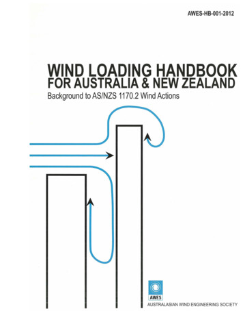
Copyright 2014 Altair Engineering, Inc. Proprietary and Confidential. All rights reserved.Freestream Turbulence (Steady-State Mid Mesh) There is a clear trend in wind loading and Y-moment as functions offreestream turbulence level, Yet, little effect ( 3%) in the range [10,1e6] of freestream viscosity ratio.Run Numberrun09run14run19run18Difference (18 -09)Inlet νt1.454E-041.454E-011.454E 001.454E 01Inlet νt/ν1.E 011.E 041.E 051.E 06Wind Loading (MN)6.4596.4776.5026.6272.6%Moment-Y (MN.m)280.2280.6281.5282.60.9%
Copyright 2014 Altair Engineering, Inc. Proprietary and Confidential. All rights reserved.Freestream Turbulence – νt/ν 1e6 The little effect of freestream turbulence level is due to: Even larger turbulence level generated in the wake behind the model, Wake-dominated or “form” (in contrast to skin-friction) drag based wind loading.
Copyright 2014 Altair Engineering, Inc. Proprietary and Confidential. All rights reserved.3. Detached Eddy Simulation (DES)High Fidelity Turbulence Modelling
Copyright 2014 Altair Engineering, Inc. Proprietary and Confidential. All rights reserved.DES Turbulence – Mid Mesh ; Δt 25ms Mid mesh was used: Same timestep size as the URANS simulation, i.e., Δt 25ms Inlet B.C. identical to that of the URANS simulation, i.e., constant Eddyviscosity with νt /ν 10. No synthetic turbulence imposed at inlet Initial condition: URANS transient solution
Copyright 2014 Altair Engineering, Inc. Proprietary and Confidential. All rights reserved.DES Turbulence – Solution HistoryClose-up280-timestep averageClose-up280-timestep average
Copyright 2014 Altair Engineering, Inc. Proprietary and Confidential. All rights reserved.DES Turbulence – Summary of Data There is 5% increase in average wind loading using DES. Maximum instantaneous wind loading shows 10% rise compared withthe steady-state valueMax Surface Element Size(m)First Layer Height(mm)Wind ESavg – RANS---4.5%9.7%DESmax – RANS---10.5%32.2%DES RANS : Steady-state Spalart-Allmaras turbulence modelURANS : unsteady (transient) Spalart-Allmaras turbulence modelDES : Delayed DES formulation of Spalart et. al., published in 2006
Copyright 2014 Altair Engineering, Inc. Proprietary and Confidential. All rights reserved.DES Turbulence – Performance About 80% increase in CPU time from URANS to DES simulation.Running CPU(sec)CoresRunning CPU(hour)TimestepsTimestep Size(ms)Physical 70DES28118612878.1560025140 Running on cluster of Intel Xeon Processor E5-2670 (8-core 20M Cache 2.60 GHz)
Copyright 2014 Altair Engineering, Inc. Proprietary and Confidential. All rights reserved.DES Turbulence – Iso-Surface Iso-Surface of X-velocity; -1m/s Coloured in pressure level
Copyright 2014 Altair Engineering, Inc. Proprietary and Confidential. All rights reserved.Velocity Field – URANS
Copyright 2014 Altair Engineering, Inc. Proprietary and Confidential. All rights reserved.Velocity Field – DES More unsteady (instantaneous) turbulent flow structures are captured.
Copyright 2014 Altair Engineering, Inc. Proprietary and Confidential. All rights reserved.Wind Direction ( Y)(90deg rotation about Z axis)
Copyright 2014 Altair Engineering, Inc. Proprietary and Confidential. All rights reserved.Wind Direction ( Y) – Model Configuration
Copyright 2014 Altair Engineering, Inc. Proprietary and Confidential. All rights reserved.Wind Direction ( Y) Freestream turbulence viscosity ratio 10.Steady-StateNumber ofElements(million)Max SurfaceElement Size(m)First LayerHeight(mm)Wind Load(MN)Momentabout X-axis(MN.m)Run 1527.91.04.04.450-187.3X momentWind Loading
Copyright 2014 Altair Engineering, Inc. Proprietary and Confidential. All rights reserved.Wind Direction ( Y)
Copyright 2014 Altair Engineering, Inc. Proprietary and Confidential. All rights reserved.Wind Direction ( XY)(45deg rotation about Z axis)
Copyright 2014 Altair Engineering, Inc. Proprietary and Confidential. All rights reserved.Wind Direction ( XY) – Model Configuration
Copyright 2014 Altair Engineering, Inc. Proprietary and Confidential. All rights reserved.Wind Direction ( XY) Freestream turbulence viscosity ratio 10.Steady-StateNumber ofElements(million)Max SurfaceElement Size(m)First LayerHeight(mm)Wind Load(MN)Run 1627.91.04.06.255
Copyright 2014 Altair Engineering, Inc. Proprietary and Confidential. All rights reserved.Wind Direction (-X)(180deg rotation about Z axis)
Copyright 2014 Altair Engineering, Inc. Proprietary and Confidential. All rights reserved.Wind Direction (-X) Freestream turbulence viscosity ratio 10.Steady-StateNumber ofElements(million)Max SurfaceElement Size(m)First LayerHeight(mm)Wind Load(MN)Run 2427.91.04.04.771
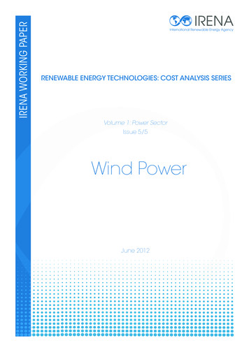
Copyright 2014 Altair Engineering, Inc. Proprietary and Confidential. All rights reserved.Wind Direction (-X) A completely different flowfield.-X wind X wind
Copyright 2014 Altair Engineering, Inc. Proprietary and Confidential. All rights reserved.Summary of Results CFD shows up to 45% reduction in the predicted wind loading comparedwith the semi-empirical data.Wind Load X (MN)Wind Load-X (MN)Wind Load Y (MN)Wind Load XY i-Empirical(SE)-8.7088.7086.2558.041RANS – SE--26%-45%-29%-22%DESavg – SE--23%---DESmax – SE--18%---RANSDES
Copyright 2014 Altair Engineering, Inc. Proprietary and Confidential. All rights reserved.Concluding Remarks With Altair’s AcuSolve, CFD was used to predict wind loading ontypical topside of offshore platform structure The predicted wind loading and moment show small to nodependency on mesh size, timestep size, steady-state vs transient,freestream turbulence level, and turbulence model This pertains to the fact that for this specific and typical geometry,wind loading mainly consists of “form” (pressure) drag, as a resultof the large separation off the corners of the windward face The CFD results show a reduction of up to 45% in wind loadingprediction compared to semi-empirical methods currently adoptedby industry
Copyright 2014 Altair Engineering, Inc. Proprietary and Confidential. All rights reserved.Concluding Remarks It is clear that CFD becomes increasingly relevant and imperative withincreasing complexity of the topside geometry Steady-state RANS should be used for a quick prediction of the windloading on such structures For more detailed and accurate prediction, the DES transient approachshould be adopted.
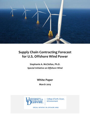
Copyright 2012 Altair Engineering, Inc. Proprietary and Confidential. All rights reserved.Future Work? Methane Dispersion example: AirportTerminal Exhaust Simulation – cut plane at 1 mheight of 1%
Copyright 2014 Altair Engineering, Inc. Proprietary and Confidential. All rights reserved.
To demonstrate the utility of CFD using AcuSolve in improving the prediction of wind loading on typical large offshore platform topside Current wind loading assessment is based on semi-empirical methods, nowadays widely used in the offshore industry. These tend to over - estimate wind loading on the topside structure