Transcription
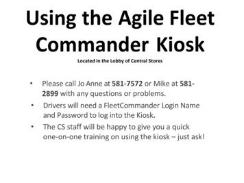
These plans are obsolete. Pleasefollow this link to revised plansPlans for KioskWe have built two small kiosks for the Finger Lakes Land Trust. The kiosks are designed to below-cost, attractive (in a natural/rustic fashion), functional, long-lasting, and maintenance-free.We also wanted to avoid the use of pressure-treated lumber and manufactured materials to thegreatest extent possible so that the kiosks would fit more comfortably in a natural setting. Webelieve that we have accomplished most of these objectives; time will tell on the “long-lasting,and maintenance-free.”The kiosk on the FLT at Sweedler Preserve at Lick Brook Copyright, 2010, Finger Lakes Land Trust and Roger A. HopkinsPage 1These plans may be used for non-commercial projects only. Include complete document if these plans are share or copied. Please let us knowabout your project if you use these plans.
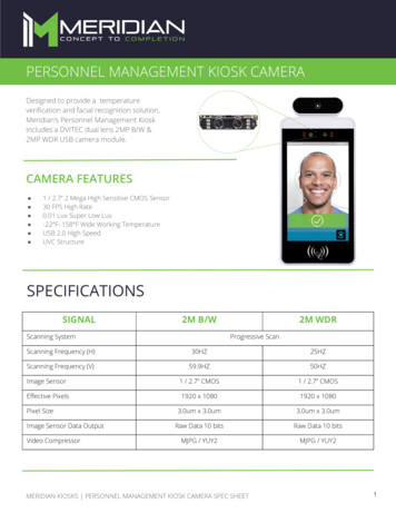
The kiosk at Kingsbury Woods Nature PreserveKingsbury kiosk with trailhead register box Copyright, 2010, Finger Lakes Land Trust and Roger A. HopkinsPage 2These plans may be used for non-commercial projects only. Include complete document if these plans are share or copied. Please let us knowabout your project if you use these plans.
Black locust?We decided to build the kiosks using rough-cut black locust lumber. This helped us meet theobjectives of a natural, rustic appearance, and avoidance of pressure-treated lumber. Black locustis naturally rot-resistant. (We still find split black locust fence posts from the late 19th centuryalong the Finger Lakes Trail!)It may be difficult to find black locust cut to the dimensions you need. You will need to handselect virtually every piece since knots, cavities, and irregular dimensions are common. It isfairly easy to work when it is not well seasoned, but once seasoned, it is extremely hard. Youmust use carbide cutting tools. You must also pre-drill full length holes for your screws and usesoap on the threads to avoid breaking them off. Also, black locust is prone to warping andsplitting as it seasons, so it is important that you assemble a structurally sound kiosk withaccurate cuts so the pieces mate well. A final treat is that slivers from rough-cut black locust arequite nasty, and some have reported allergic reaction to the fine sawdust. Not to sound toonegative, once you have gotten used to working with black locust, you will find it a beautifulwood capable of giving very satisfying results. Copyright, 2010, Finger Lakes Land Trust and Roger A. HopkinsPage 3These plans may be used for non-commercial projects only. Include complete document if these plans are share or copied. Please let us knowabout your project if you use these plans.
The projectThere are three phases to the project.Selecting the woodPlan on spending several hours at the sawmill, and probably more than one trip. Make sure thatyou have gloves, a measuring tape, these plans, and a notebook. Black locust is heavy so don’tplan on using a roof rack for all of the lumber in one trip.Pre-fabricationThis involves building the leg assemblies and precutting all of the pieces except the panelbrackets (which should be squared on one end and then cut to length during construction). Youwill want to do this in your shop and will need an accurate miter saw, power drill and appropriatebits. Mark pieces that are fitted together so they can be matched up during construction. Plan onspending 4-6 hours in the shop.ConstructionYou will need at least one helper and preferably 2 or 3. Construction will probably take a fullday. If the holes and alignment go slowly, you may need part of a second day to finish.Here is the general order of business:1. Dig two holes. We try to keep the holes as small as possible using the undisturbed soilaround the holes for support and minimizing the amount of concrete or other fill. Butdon’t have the holes so small that you have trouble with alignment. Remember that youmay have to move the bottom of the leg as well as the top.2. Align the legs3. Attach the ridge beam and the horizontal panel brackets to the legs4. Fill in the holes5. Lunch6. Attach rafter supports and working rafters to legs and ridge beam7. Attach bottom roof boards front and back8. Attach next two roof boards front and back9. Attach the lazy rafters to the ridge beam and the three roof boards front and back10. Attach the fourth roof boards front and back, then the ridge cap11. Finish the panel12. Finish the ground clean-upHere is what you will need at the site: Two six foot step ladders5′ Rock barWrecking bar or pry bar Copyright, 2010, Finger Lakes Land Trust and Roger A. HopkinsPage 4These plans may be used for non-commercial projects only. Include complete document if these plans are share or copied. Please let us knowabout your project if you use these plans.
Post-hole diggerShovelPulaski or similar for light landscapingLoppers for cutting roots in the holesRake4-foot carpenter’s levelMeasuring tapesCarpenter’s square or other squaring toolMarkers and pencilsThree or four 1″ 3″ 12′ furring strips for bracesTwo 1″ 3″ 5′ furring strips for braces while aligning the legsSeveral blocks, for example 1″ 4″ 6″Four 24″ iron stakesHand sledgehammer, for driving stakes and nudging the alignmentClaw hammer or framing hammerClampsMore clampsStrong battery powered drill, drill bits, screw driver bits, and extra batteries. You willwant two drills for doing the roof, one with a drill bit and one with a screwdriver bit. Youcan pass them back and forth to two workers.Some way to keep the fasteners organized⅜″ Drill bit or auger for the carriage bolts.⅞″Spade bit for countersinking the carriage boltsSocket wrenches for carriage boltsWater for the concreteGloves for all handsPlans, notebook, cameraOptional: Two sawhorses and table top of some sort to keep tools and materials off theground Copyright, 2010, Finger Lakes Land Trust and Roger A. HopkinsPage 5These plans may be used for non-commercial projects only. Include complete document if these plans are share or copied. Please let us knowabout your project if you use these plans.
In the shopThe legsThe legs are made from girders fabricated (in your shop) from 2 x 4, 2 x 6, and 5/16 x 5” lagbolts or structural screws. This construction will be almost as stiff as a 6 x 6 without theadditional weight or board foot cost. Also, the two pieces will work together to prevent warpingin the other piece. Finally, the cutouts for the ridge beam and the rafters are much easier. (Notethat these cutouts are done before the pieces are screwed together.)The holes for the screws need to be pre-drilled, especially if the wood is seasoned. Measure andlay out the location of the screws carefully so that you end up with a nice clean appearance. Ifusing lag screws, first drill a 7/8″ diameter countersink hole about the depth of the screw head.Then drill a pilot hole about 1/16 smaller than the screw. If using structural screws, it may not benecessary to countersink the heads. You will probably have to clamp the pieces together to getthem to line up since the pieces will undoubtedly have some curvature. Once clamped, drill all ofthe holes and put in the screws before loosening the clamps.Bevel cutout forfront rafter5″ structural screws(6-8 needed)2″ 6″ 10′Straight cutout forridge beam10′2″ 4″ 10′Cutout to receivefront rafter30 2″ 4″2″ 6″2″ 4″Make cutouts in the tops of the 2 x 6 leg piecesto receive the front rafters. These are moredifficult since this is a blind cut and because ofthe bevel. The width of the cutout should equalthe thickness of the rafters. If the rafters are ofvarying thicknesses, pick two and measure theCutout to receiveridge beam2″ 6″Make cutouts in the tops of the 2 x 4 leg piecesto receive the ridge beam. These are easy tomake with two cuts. The cutout should be 2″deep with the width equal to the thickness ofthe ridge pole (2″ if using rough-cut). Measurethe width carefully so that the ridge beam willfit snugly, but not too tight that you will havetrouble at assembly time. Copyright, 2010, Finger Lakes Land Trust and Roger A. HopkinsPage 6These plans may be used for non-commercial projects only. Include complete document if these plans are share or copied. Please let us knowabout your project if you use these plans.
cutouts carefully. Then mark the rafters so they stay matched up with the cutouts.As you make the cutouts, remember that the left and right legs are different. The drawing aboveshows both legs. Pick the best sides (visually) of the leg pieces to face front and to the sides.The rafter supportsCut the two rafter supports. Start with a 44″ section of 2 x 4 and cut the top bevels at 30 . Thebottom bevels are cosmetic but should be about 15 .44″4″2″30 4″3½″ Copyright, 2010, Finger Lakes Land Trust and Roger A. HopkinsPage 7These plans may be used for non-commercial projects only. Include complete document if these plans are share or copied. Please let us knowabout your project if you use these plans.
The raftersCut the four working rafters that will connect from the Ridge to the rafter supports. Start with a24″ section of 2 x 4. Layout the angles at the top of the rafter and cut them with a miter saw. Usethe rafter support (shown in red below) as a template to layout the angles at the bottom of therafter and then cut them with a miter saw.1″Rafter30 Rafter support30 Next cut four spacer pieces from 1′ sections of 2 x 4 as shown in yellow below. These are neededsince the rafter support is on the outside of the leg, but the rafters are on the inside of the 2 x 4section of the leg. Use the rafter as a template to lay out the angles and then cut on a miter saw.You may find it easier to cut the angles on the end of a longer piece and then use a simplecrosscut to cut the spacers to length. The actual length is not too important but should be thesame for all four.1″30 30 Copyright, 2010, Finger Lakes Land Trust and Roger A. HopkinsPage 8These plans may be used for non-commercial projects only. Include complete document if these plans are share or copied. Please let us knowabout your project if you use these plans.
Aligning the raftersTo check the alignment, lay two rafters on the floor with a piece of 2″ 4″ standing on edgebetween them (green below) to simulate the ridge beam. This 2″ 4″ should be the samethickness as the actual ridge beam. Then lay the rafter support across as shown below in red. The44″ width of the rafter support was based on the ridge beam being exactly 2″ thick. If you have adifferent thickness, or much variation in your rafters or your angles, you may have to trim theangled ends of the rafter support slightly. This is a lot easier to do now than during construction.You should do this for both ends of the kiosk. If there is much variation in your rafters, markthem once you have them fitted so you can match them up during assembly.“Lazy” raftersCut the remaining six “lazy” rafters in the same way that you cut the 4 working ones. The onlydifference is that you might consider using lighter weight 2″ 4″ stock. For example, if you findsome that are closer to 1½″ 3″ inches, they will work just fine. Their only purpose is to holdthe roof boards together; they are not supporting any weight. In fact, they are adding to theweight being supported by the roof boards. Also, the spacers are not needed.Roof capConsider cutting drain grooves the length of the roof cap piece as shown to prevent rain waterfrom siphoning back under the roof cap. Copyright, 2010, Finger Lakes Land Trust and Roger A. HopkinsPage 9These plans may be used for non-commercial projects only. Include complete document if these plans are share or copied. Please let us knowabout your project if you use these plans.
The display panelThe display panel has overall dimensions of 48″ wide and 36″ high. It is made from a sandwichof ½″ MDO plywood, ½″ Homosote Corkboard, and ⅛″ clear Lexan.Both the MDO and the Corkboard are a full 48″ 36″ inches and can be cut from a 4′ 8′ sheet.Since both are rather expensive, cut carefully. This will give you material for two kiosks withfactory cut sides and leave enough left over for a display panel of 4′ by slightly less than 2′. Thefactory cut sides on the 48″ 36″ are very useful for squaring up the legs and the panel brackets.The Lexan should be ordered cut to size and will be approximately 45½″ 33½″ to allow a 1¼″margin on all four sides for the frame. It is best to build the frame first and then measure theexact dimensions for the Lexan. Remember that you need allow a bit more than ⅛″ forhorizontal and vertical expansion. So for example, if your frame measures exactly 45½″ wide,order the Lexan 45⅜″ wide.2½″ od48″2″ 4″ Display brace(top and bottom)or1″ 3″ Display backing(left and right)Display panel frameMake the display panel frame from nice straight pieces of 1″ x 2″ black locust. You will needtwo 36″ pieces and two 48″ pieces. Rip both sides to get a width of 1½″. Then resaw the top andbottom to get a thickness of ¾″.1½″Cut rabbet groves along one side of thepieces ½″ wide and ¼″ deep as shownbelow. Cut 45 miters on the corners to fitto a frame measuring 36″ 48″.¾″¼″½″ Copyright, 2010, Finger Lakes Land Trust and Roger A. HopkinsPage 10These plans may be used for non-commercial projects only. Include complete document if these plans are share or copied. Please let us knowabout your project if you use these plans.
Display panel bracketsThere are horizontal brackets at the top and bottom of the display. These are made from two 2″ 4″ 56″ pieces. They should be fairly straight, but can have imperfections on the back side oredges. Cut them a bit long and then trim to exact fit during construction.You will attach the horizontal brackets to the back of the legs inside the 2″ x 4″ side members ofthe legs. Use four 3½″ deck screws. Use the MDO Plywood panel as a square to make sure thatthe legs are parallel, vertical, and exactly four feet apart measured from the inside edges of the2″ 6″ members. Then trim the horizontal brackets to length and clamp along the top and bottomof the MDO panel. Then drive the screws in the four corners from the back of the kiosk. Notethat the horizontal brackets are somewhat structural in addition to supporting the display panel.The vertical brackets serve only to provide an attachment point for the sides of the display panel.These are made from 1″ 6″ 28″ boards. Cut the boards a bit long and then trim to exact fitduring construction.You will attach the vertical brackets to the back of the legs between the two horizontal brackets.Use 4 or more 2½″ deck screws driving them from the back of the kiosk.2″ 4″ 56″Display bracket(2 needed)3½″ deck screws(from back)2½″ deck screws(from back)1″ 6″ 28″Display side bracket(2 needed)36″48″ Copyright, 2010, Finger Lakes Land Trust and Roger A. HopkinsPage 11These plans may be used for non-commercial projects only. Include complete document if these plans are share or copied. Please let us knowabout your project if you use these plans.
On the siteAligning the structureThe main challenge in building the kiosk is getting the two legs vertical, parallel, and exactly 4′apart as measured from the inside edges of the legs. Additional complications are that the tops ofboth legs need to be at the same level, and the fronts of the two legs need to be in the same plane(in other words, not twisted with respect to each other).We have had the best luck with the followingsequence:1. First, try to get bottom of both holes atapproximately the same level. Do this byleveling a board between the two holes andthen measuring from the board to the bottomof each hole. If you find a slight difference,work with the less deep hole since the otherone can be filled in slightly. This will be thefirst leg. If there is a difference of more than afew inches (for example, you hit bedrock),then work with the deeper hole, planning tocut the bottom off of the other leg. (If youcan’t get both legs at least 24″ into the ground,consider moving to another location.)1st law of kiosk building: The hugeboulder or bedrock will always befound 20” into the second hole.2. Put both legs in their holes.3. Clamp one end of a 5′ furring strip to the front face of the first leg. Then, with both legsapproximately vertical, clamp the other end of the furring strip to the other leg. This willmake sure that the fronts of both legs remain in the same plane as you align the first leg.4. Make the first leg accurately vertical using a good carpenter’s level. The leg needs to bevertical left and right as well as front to back. Then use 1″ 3″ 12′ furring strips asbraces to hold the leg in position. One brace should be anchored well to the side and theother well to the back of the kiosk. Make sure that the side brace is in the plane of thefront of the legs and that the back brace is 90 from that.5. Fit the ridge beam in place between the two legs and use it to level the tops of the legs.Measure any difference and then correct the second leg by filling in its hole or cutting offthe bottom of the leg (or deepening the hole) to brings the tops level.6. Check that the first leg is vertical and aligned in the plane of the front of the legs.7. Decide on the height of the display panel. Normally bottom of the panel is 3′ above theground. Clamp a block of wood at this height to the inside of the first leg to support thebottom corner of the MDO panel. Copyright, 2010, Finger Lakes Land Trust and Roger A. HopkinsPage 12These plans may be used for non-commercial projects only. Include complete document if these plans are share or copied. Please let us knowabout your project if you use these plans.
8. Clamp a temporary support to the bottom edge of the MDO panel on the other side tohold the weight and keep it horizontal. Use a clamp on the first leg at the top of the MDOpanel to keep the panel vertical.9. With the MDO panel snugly against the first leg (and the first leg well aligned) adjust thesecond leg using the MDO panel as a guide. This will make the second leg vertical left toright. Use your carpenter’s level to get the second leg vertical front to back. You mayneed to move the bottom or the top to prevent twisting the legs out of the desired plane.Aligning the tops of the legs (left) and squaring the legs using the MDO panel (right)10. At this point, the legs should be aligned. Clamp the second leg to braces or to the first legand MDO panel.11. Then with the legs aligned, adjust the left to right position of the ridge beam and attach it.Then trim the length of the horizontal panel brackets to actual measurement and attachthem. Clamp the horizontal panel brackets to the MDO panel to align them.12. Finally, fill the holes with concrete mix and water. Give the concrete a few minutes to setup before you begin working on the roof, and work carefully so as not to disturb thealignment until the concrete is well set.Some people like to pre-mix the concrete and pour it wet into the holes, while others pourthe concrete mix in dry and then add water into the hole. Check out the quick-set concretemix that is formulated for this technique; but be aware that it does set very quickly andyou will not have much time to correct any alignment problems.Some people prefer rocks, gravel, tightly packed soil, or rock dust rather than concrete toanchor the legs. Copyright, 2010, Finger Lakes Land Trust and Roger A. HopkinsPage 13These plans may be used for non-commercial projects only. Include complete document if these plans are share or copied. Please let us knowabout your project if you use these plans.
The RoofPosition the ridge beam in place and securewith 4″ deck screws through the 2″ 6″member of the leg assembly.Ridge beam4″ deckscrews2″ 6″Clamp the rafter support into approximateLegposition on the outside of the leg assembly.assemblyPlace the front rafter in position and then2″ 4″with a rafter spacer between it and the rafterFRONTsupport, clamp the rafter support, spacer, andrafter together. Then position the back rafterand clamp it to the back of the rafter supportalong with a rafter spacer. Don’t worry aboutpositioning the rafter spacers; the problem of the moment is to get both rafters and the raftersupport lined up. Two people are needed for this.When rafters and the rafter support are aligned, tighten the clamps and then drill the holes for thetwo carriage bolts and insert and tighten them. Then align the rafter spacers, tighten the clampsthere, and then drill the holes for the carriage bolts at the end of the rafter support and insert andtighten them. Finally, put two 4″ deck screws through the top of the rafters into the ridge beam.Note where these screws are so you don’t hit them when attaching the roof and the ridge cap.4″ deckscrews¾″ 4″ 8′ridge board⅜ 6″carriage bolt⅜ 4″carriage boltFRONT2″ 6″3½″ deckscrews⅜ 6″carriage bolt2″ 4″Attach the ridge board to the ridge beam using two 4″ deck screws. Drive the screws between therafter locations so they don’t interfere with the other screws. Copyright, 2010, Finger Lakes Land Trust and Roger A. HopkinsPage 14These plans may be used for non-commercial projects only. Include complete document if these plans are share or copied. Please let us knowabout your project if you use these plans.
Attach the ¾″ 4″ 8′ ridge board by driving several 4″ deck screws down into the ridge beam.Start the roof at the bottom by clamping a roof board to the two rafters. Then drive a 4″ deckscrew through the roof board into the rafter. Attach the bottom board to the back rafters in thesame way. This will prevent the ends from twisting as you build the roof. Then do a rough layoutof the next three roof boards in the front. You want the overlaps to be about the same and the toproof board snug up against the ridge board. Mark the position of the boards and then work fromthe bottom up by clamping the second board to the two end rafters, and then securing with a 4″deck screw. Do only second board front and back now. You will do the third and fourth boardsfront and back after the lazy rafters are in place.¾″ 8″ 8′roof board¾″ 8″ 8′ridge cap4″ deckscrews¾″ 4″ 8′ridge board FRONT2″ 6″ 2″ 4″Clamp the lazy rafters to the bottom roof board and align with the ridge beam. Secure the lazyrafter to the ridge beam with a 4″ deck screw. Then with the clamp still in place, drive the 4″deck screws through the roof boards into the lazy rafter. Repeat for the all of the lazy rafters. Copyright, 2010, Finger Lakes Land Trust and Roger A. HopkinsPage 15These plans may be used for non-commercial projects only. Include complete document if these plans are share or copied. Please let us knowabout your project if you use these plans.
“Lazy” raftersTo complete the roof, attach the third and fourth roof boards front and back, and then screw theridge cap down through the ridge board into the ridge beam. Use five 4″ deck screws along thelength of the ridge, offset slightly from the rafters to avoid interfering with the other screwsalready in place.Before attaching the ridge cap, consider cutting drip grooves as shown on Page 9. We did have aslight problem with water siphoning back under the ridge cap that this should prevent. Copyright, 2010, Finger Lakes Land Trust and Roger A. HopkinsPage 16These plans may be used for non-commercial projects only. Include complete document if these plans are share or copied. Please let us knowabout your project if you use these plans.
Maintaining the Display panelYou will need to instruct the person responsible for the content of the display panel, and providethem with the proper driver for the trim screws. Here is how to remove the Lexan: Remove all ofthe screws from the vertical frame piece on the right side of the panel. Remove the frame pieceand set it aside with the top end up. Slide the lexan sheet slightly to the right so that it is freefrom the left side frame piece. Then lift the horizontal center of the Lexan away from thecorkboard to buckle the sheet enough to free it from the top frame piece. You can then removethe Lexan sheet and carefully set it aside. Reverse the process after changing the content. Anoffice stapler is probably the best way to attach paper to the cork board. Hopefully, it should notbe necessary to laminate the content.Kadillac KioskThe kiosk shown below was professionally designed and was constructed and installed usingsimilar techniques to those described above. The kiosk features two professionally printed panelsand a bulletin board display panel (not completed in this photo) for display of changing content.The roof is flat boards, membrane, and cedar shakes. The vertical posts are 6 x 6 black locust.Kiosk at Roy H. Park Nature Preserve Copyright, 2010, Finger Lakes Land Trust and Roger A. HopkinsPage 17These plans may be used for non-commercial projects only. Include complete document if these plans are share or copied. Please let us knowabout your project if you use these plans.
Bill of materialsQuantityItemDescription22″ 6″ 10′2142″ 4″ 10′2″ 4″ 8′2″ 4″ 24″62″ 4″ 24″191″ 4″ 8′¾″ 8″ 8′22″ 4″ 5′21″ 6″ 30″21″ 2″ 8′148″ 36″ MDOPlywood48″ 36″corkboardHomosote45½″ 33½″ ⅛″ There are two inferior grades between Lexan andLexan“plexigrass” which might work, but Lexan is preferred forstrength (pretty much unbreakable) and no discoloration.5/16″ 5″For attaching the front and side members of the leggalvanized lagassemblies. Comparable structural screws could be used.screw1112Leg fronts. Should be full 2″ 4″. Should be as straight aspossible with 3 good edges for 7½ feet of length. The endto be buried can have defects.Leg sides. Same as fronts.Ridge beam. This should be straight with square edges.Working rafters. Should be full 2″ 4″. Plan on cuttingfrom 8-footers if you can get 3 or 4 good pieces. It helps ifthese are fairly similar and consistent in width andthickness, with straight, square edges.Lazy rafters. Can be same as above, but lighter weight andsome variation is OK. Cut from 8-footers.Ridge board. This should be straight with square edges.Roof boards. If possible, get these cut to order rather thanusing full one-inch thick rough cut. This will reduce theweight of the roof. There can be some imperfections onthe edges since there is 1½″ - 2″ of overlap. But thereshould be no holes in the middle. Some warp is OK sincethese will be screwed down, but the edges should be fairlystraight. There can also be some variation in width as longas you plan for it. Save the best ones for the ridge cap andthe bottom front.Horizontal display brackets. These are out of sight in theback and can have some imperfection. Square one end inthe shop and then cut to exact length during assembly.Vertical display brackets. These are out of sight in theback and can have some imperfection. Square one end inthe shop and then cut to exact length during assembly.Display frame. You will rip these to 1½″ and resaw to ¾″thick and then cut 48″and 36″ pieces. These want to bestraight and uniform so you end up with a nice lookingframe to hold the Lexan. If you find a single nice 1″ 4″ 8′ you could use that instead.This is waterproof, but it wouldn’t hurt to paint the backside.Keep this protected until final assembly. Copyright, 2010, Finger Lakes Land Trust and Roger A. HopkinsPage 18These plans may be used for non-commercial projects only. Include complete document if these plans are share or copied. Please let us knowabout your project if you use these plans.
QuantityItem48⅜ 4″galvanizedcarriage bolt⅜ 6″galvanizedcarriage bolt2½″ deck screws203½″ deck screwsAttach vertical panel brackets from back into 2 x 6 legfronts. 8 are needed.Attach top of rafters to leg assemblies, one through frontrafter into 2 x 6 and one through back rafter into 2 x 4. 4needed4″ deck screwsAttach horizontal panel brackets from back into 2 x 6 legfronts. 16 are needed.Attach ridge beam to leg assemblies, one through 2 x 6into front of ridge beam and one through 2 x 4 into backof ridge beam. 4 needed.459DescriptionAttach rafter support to legs, two at each end.Attach end of rafter support, through rafter spacer to rafterends.Attach ridge board to ridge beam. 2 needed.Attach roof boards to rafters. 50 are needed.222½″ stainlesstrim screws3-440 lb. concretemixAttach ridge cap through ridge board into ridge beam. 5are neededAttach frame though Homosote and MDO plywood to 1 x6 vertical bracket on sides and 2 x 4 horizontal bracketstop and bottom.Consider the quick-setting mix.Roger Hopkinsroger@naturalhighs.netSweedler: Thanks to Betsy Darlington (inspiration), Tom Brown (black locust), Dave Schurman(clamps, garage, and advice), Gary Mallow (encouragement & sweat), Will Hopkins (concrete& counsel), Carl Leopold (appreciation)Kingsbury: Thanks to Chris Olney (make it happen), Sheila Kingsbury (site), Tom Brown (blacklocust), Dennis Baldwin (Eagle Scout in waiting) and comrades, Baldwin/Costich family (pizza,transportation, impossibly tall and heavy step ladder, immeasurable help) Copyright, 2010, Finger Lakes Land Trust and Roger A. HopkinsPage 19These plans may be used for non-commercial projects only. Include complete document if these plans are share or copied. Please let us knowabout your project if you use these plans.
3. Attach the ridge beam and the horizontal panel brackets to the legs 4. Fill in the holes 5. Lunch 6. Attach rafter supports and working rafters to legs and ridge beam 7. Attach bottom roof boards front and back 8. Attach next two roof boards front and back 9. Attach the lazy rafters to the ridge beam and the three roof boards front and back 10.