Transcription
The Audi 4.0l V8 TFSI enginefrom the EA825 serieseSelf Study Program 920493
Audi of America, LLCService TrainingCreated in the U.S.A.Created 2/2020Course Number 920493 2020 Audi of America, LLCAll rights reserved. Information contained in this manual is based on thelatest information available at the time of printing and is subject to thecopyright and other intellectual property rights of Audi of America, LLC.,its affiliated companies and its licensors. All rights are reserved to makechanges at any time without notice. No part of this document may bereproduced, stored in a retrieval system, or transmitted in any form or byany means, electronic, mechanical, photocopying, recording or otherwise,nor may these materials be modified or reposted to other sites withoutthe prior expressed written permission of the publisher.All requests for permission to copy and redistribute information should bereferred to Audi of America, LLC.Always check Technical Bulletins and the latest electronic service repairliterature for information that may supersede any information included inthis booklet.The eSelf-Study Program (eSSP) teaches a basic understanding of the design and mode of operation of new models, newautomotive components or new technologies.It is not a repair manual! Figures are given for explanatory purposes only and refer to the data valid at the time ofpreparation of the SSP.For further information about maintenance and repair work, always refer to the current technical literature.Release Date: February 20202
Introduction Engine description and special features Technical data Engine mechanics Cylinder block Crankshaft Cylinder head Camshaft drive configuration Crankcase ventilation system Positive Crankcase Ventilation (PCV) Fuel tank ventilation Vacuum system Oil supply Oil circuit overview Oil pump Piston cooling Sensors and actuators Oil filter and oil-coolant heat exchanger Oil filter module Oil supply in the cylinder head cover 56788121831364142444646485051535455Drive for ancillaries 56Cooling system 58System overview Coolant circuit in cylinder block Cooling concept for the cylinder head Transmission coolant circuit Air supply Overview of air ducts Intake manifolds Throttle Valve Control Modules GX3 and GX4 Turbocharging Twin scroll exhaust manifold Twin scroll turbochargers Turbocharger mounting Turbocharger oil and coolant connections Heat shield in inner V of engine 5860626769697172737374767778Exhaust system 79Fuel system 80High-pressure injector Engine management System overview Engine Control Module Inspection and maintenance Service information and operations Special tools and workshop equipment Knowledge assessment 81828284858586873
4
IntroductionThe new Audi V8 engine from the EA825 series is a jointdevelopment of Porsche and AUDI AG. The engine construction is based on the V6 engine from the EA839 series. Thishas advantages not only for the manufacturing process; theclose relationship has benefits for after sales service aswell. For example, many of the special tools can be used forboth engines.The new V8 engines were first introduced by two otherGroup brands: Bentley and Porsche. At Audi, the new V8will be installed first in the A8.The engines are manufactured in the new Porsche engineproduction facility in Zuffenhausen.676 153Learning objectives of this eSelf-Study Program:This eSelf-Study Program describes the function of the 4.0lV8 TFSI engine of the EA825 engine series. Once you havecompleted this eSelf-Study Program, you will be able toanswer the following:›››››What are the technical characteristics of the engine?How do the oil supply and engine cooling systems work?What are the special features of the air supply system?What effect does the improved injection system have?What has changed for after-sales service and maintenance?5
Engine description and special Eight-cylinder V-engine with 90 bank angleAluminum cylinder blockChain drive valve timingFour valves per cylinder, double overhead camshafts (DOHC),roller cam followers, variable valve timingTurbochargers with charge air cooling (maximum chargepressure: 31.9 psi [2.2 bar] absolute)Emission control system with pre and main catalyticconverter system, Oxygen sensorsHigh-pressure and low-pressure fuel systems(controlled according to demand)Cylinder on Demand (CoD)Indirect charge air cooling systemFully electronic direct injection with electric throttleAdaptive Oxygen sensor controlMapped ignition with single ignition coilsCylinder-selective adaptive knock controlThermal management systemAdvantages over the previous version V8 from the EA824 family:› High torque at low rpm› Improved responsiveness› Significant increase in efficiency› Increased power output and torque› Better fuel economy› Meets the relevant country-specific emission standards› Thermal management system (new cooling module)› Reduced engine friction› Improved injection systemHighlights of the new V8 engineCrankcase (optimized for weight) withAPS-coated cylinder running surfaceThermal managementFriction-optimizedvalve gearFuel system withcentral injectorconfigurationCylinder head design withvalve lift and Cylinder onDemand“Hot Side Inside” (HSI)turbocharging system676 0026
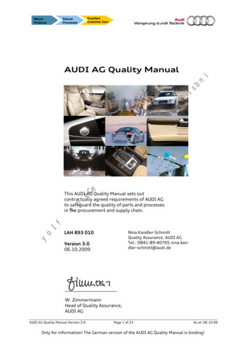
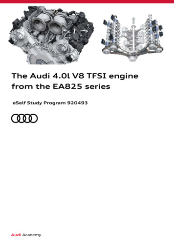
Technical dataTorque-power curve of 4.0l V8 FSI engine(engine code CXYA)486.79 lb ft(660 Nm) at1850 - 4500453.26 hp(338 kW)at 5500Diagram: engine at full loadPower output in kWTorque in Nm676 003FeaturesSpecificationsEngine codeCXYADesign8-cylinder engine with 90 V angleCapacity243.85 cu in (3996 cm)3Stroke3.38 in (86.0 mm)Bore3.38 in (86.0 mm)Cylinder spacing3.22 in (82.0 mm)Number of valves per cylinder4Firing order1-3-7-2-6-5-4-8Compression ratio11.0 : 1Power output at rpm453.26 hp (338 kW) at 5500Torque at rpm486.79 lb ft (660 Nm) at 1850 - 4500FuelPremium unleadedTurbocharging“Hot Side Inside” (HSI) turbochargers with charge air cooling(maximum charge pressure: 31.9 psi [2.2 bar] absolute)Engine managementBosch MG1CS008Engine weight509.2 lb (231 kg)Emission controlDual exhaust system with pre-catalytic converter and 3-way catalytic converterEmission standardULEV125, (Pr. number:7MU)Firing order during changeover to4 cylinder operation (cyl. 2, 3, 5, 8shut off)1-7-6-47
Engine mechanicsCylinder blockThe aluminum (ALSi9Cu3) cylinder block is single sand cast unit. It is a “deep skirt” design. This means the individual cylinder walls reach down as far as the upper oil sump providing a very high degree of rigidity. The entire cylinder block includingthe bearing covers and corresponding bolts weighs 86.2 lb (39.1 kg).In addition to the oil and cooling passages, the followingcomponents and assemblies are integrated with orinstalled on the cylinder block:›››››››The engine number is engraved on a plate on the front ofthe engine below cylinder bank 1. There is also a stickerwith the engine code and serial number attached to thevacuum pump cover.Oil spray jetsWater pump intermediate shaftOil pumpOil coolerCoolant pumpEngine mountingMounting points for ancillary components676 0048
Atmospheric plasma spraying (APS)To create a sufficiently robust iron running surface, thecylinder walls are first roughened with a special milling toolwhich cuts a dovetailed pattern into the cylinder. Theresulting undercuts ensure that the APS coating adheresproperly.A rotating plasma torch is then inserted into the cylinder.An arc discharge is used to create a plasma into which apowdered coating material is blown using compressed air.The powder melts and is sprayed onto the rough cylinderwall. There it solidifies and fills the undercuts thus creatinga wear layer.A layer of iron (roughly equivalent to 100Cr6 bearing steel)is applied in several layers in approximately 30 seconds.The final thickness is approximately 150 micrometers.(One micrometer equals one millionth of a meter.)Application of plasma coating676 005Wear layer on cylinder wallCylinder block676 0069
Crankshaft bearingsThe upper crankshaft bearing bosses are integral with thecylinder block. The grey cast iron bearing caps are retainedwith longitudinal and transverse bolts.Grey cast iron bearing capCrankshaft bearing shell (bottom)Crankshaft bearing shell (top)Hole for locking pin T40069(with engine removed)Transverse bolt for cross-boltingthe crankshaft bearing caps.676 00710
Sump (top section)Timing chain coverThe top section of the sump is made of an aluminum diecast alloy. Dowel pins are used to ensure exact positioningduring assembly.This die-cast component is made of an aluminum alloy; if itneeds to be removed, it can be pressed off the cylinderblock using auxiliary bolts. The engine speed sensor as wellas the crankshaft oil seal are located in the cover.Sump (bottom section)Sealing flange (pully end)The bottom section of the sump is made of an aluminumsheet metal. The oil drain plug and the oil level/oil temperature sensor are integrated with it.This component is also made of an aluminum alloy. Itprovides the attachment point for the dipstick tube and thecrankshaft oil seal.Cylinder 1Oil sealOil ringSealing flangePulley endTiming chaincoverEngine numberOil baffle plateOil pan top sectionOil pan bottom sectionOil drain plugOil Level Thermal SensorG266676 008NoteHousing cover and sumps are sealed by a liquid gasket (see ElsaPro for details).11
CrankshaftThe forged steel crankshaft is supported by five mainbearings to ensure a smooth running engine.The cylinder banks are positioned at a 90 degree angle toone another with connecting rods of the cylinders oppositeof each other sharing the same bearing journal.676 00912
Crankshaft bearingsThe IROX bearings conform to the high demands of hybriddrive and start/stop operation.Three-layer bearing construction:›››The steel backbone provides the required stability.The second layer is made of a soft metal carrier substrate towhich the third layer is fixed.The third layer consists of a polymer base with a homogeneousdistribution of filler materials which ensure the best possiblerunning and wear characteristics.Crankshaft bearingshell (top)Timing gear(drive gear)Crankshaft bearing 1(pulley end)Chain sprocket(drive gear for oilpump)Crankshaft bearingshell (bottom)676 01013
Thrust washersFour thrust washers (top and bottom) are installed oncrankshaft bearing four to control longitudinal movementof the crankshaft. The oil grooves of the thrust washersface towards the crankshaft.Crankshaft bearing fourThrust washer (bottom)Thrust washer (top)Crankshaft bearing shell(top)676 01314
PistonTo minimize noise, the cast pistons are mounted at a 0.5 mm offset towards the pressure side (see illustration 676 016below). Due to the compression and valve timing, intake valve recesses of different sizes are integrated in the piston crown(intake valve: large; exhaust valve: small). The chamber walls on the piston pressure side are narrower than on the counter-pressure side which is subject to less strain. The high rigidity of the pressure side makes it possible to achieve a definedpiston wear pattern while optimizing the load. On the counter-pressure side, the piston is much softer and can adapt betterto the shape of the cylinder. This combination results in different pistons for cylinder bank 1 (right bank) and cylinder bank 2(left bank).Piston rings1. Top piston ring (compression ring) mounted in the ring carrier, rectangular section seal2. Taper-faced ring3. Oil scraper ring (3 parts)Piston pinsThe steel alloy piston pins are coated and hardened. Each piston pin measures 22 mm in diameter.NoteThe small valve recesses always face the inner V.676 014Piston pressure sideCounter-pressure sideCounter-pressure sidePiston pressure side676 01615
Connecting rodsThe cracked trapezoidal connecting rods are made of high-strength steel. The bushing in the upper connecting rod smallend is made from a copper alloy (CuNi9Sn6). The connecting rod bearings are 22.3 mm wide. Both bearing shells areidentical. The bearings are made of three materials: a steel substrate, a bismuth-bronze alloy intermediate layer and a thinbismuth crystal lining. The connecting rods are installed at an offset to the engine’s longitudinal axis.676 017Installing the connecting rodsIt is important to install the connecting rods in the correct position. The points of the two installation markings must be inline with one another (see illustration 676 018 ). Only connecting rods of the same weight class may be installed on agiven engine.Installation markingView showing data matrix codeXX weight class of large connecting rod eyeYY weight class of small connecting rod eye676 018676 019NoteDo not interchange bearing shells during installation; if new components are installed the specifications forclearance tolerances must be observed (see Elsa Pro for details).16
Belt pulley / vibration damperA single bolt secures the pulley/vibration damper to the crankshaft, and a dowel pin locates them in the correct position.A diamond-coated washer is installed between the vibration damper and the end of the crankshaft as a locating element.The housing of the viscous vibration damper is made of forged steel, while the inertia ring is manufactured out ofaluminum. This provides the greatest possible strength against deformation caused by centrifugal force.Diamond-coated frictionwasherPulleyCrankshaft speed detection676 020Engine Speed Sensor G28 is located in the timing chain cover. It detects signals from the magnetic ring on the drive plate.Magnetic ringCarrier plateEngine Speed SensorG28676 02117
Cylinder headThe cylinder heads have the following technical features:››››››››DOHC, 4 valves per cylinder.Roller cam followers.Integral exhaust manifold.“Hot Side Inside” (HSI).Direct injection combustion process with central injector position.Audi valvelift system (AVS). Enables Cylinder on Demand (CoD) operation.Intake valves: hardened and tempered.Exhaust valves: hardened and tempered, sodium-filled hollow stems.676 02318
Noise insulationThe two-part insulating mats over the cylinder head covers help reduce noise. This provides effective insulation againsthigh-frequency ticking noises greater than 2500 Hz from the injectors and the high-pressure fuel pumps.676 044NotePay close attention to the installation order of components on the cylinder heads. Some components may belocated under the insulating mats and can no longer be installed after the mats have been installed.19
Cylinder head cover attachmentsCamshaft adjusterIgnition coilsHall senderCylinder head cover(right-side)Camshaft control valves(solenoid)676 045Timing chain case coverCylinder head gasketA three-layer metal gasket is used. It is only available in one thickness.Cylinder head gasket676 02420
Valve gear11092837645676 025Legend1.2.3.4.Roller cam followers with supporting elementExhaust valve springTwin-lip valve stem oil sealExhaust valveBi-metal valve with sodium filling and chromium-platedvalve stem ends5. Inlet valveMonometallic valves with inductive hardened valve seats6. Valve spring plate (bottom)7. Single-lip valve stem oil seal8. Inlet valve spring9. Upper valve spring plate10. Valve keepersThe valve springs are a simple cylindrical shape.21
Camshaft housingsThe camshaft housings of both cylinder banks work in thesame way; the only difference is the location of certaincomponents. The camshaft housing for cylinder bank 2 isdescribed here as an example. The cylinder head is sealedby a liquid gasket and a rubber molded gasket.The camshafts are mounted in five sleeve bearings in thecamshaft housing. The center bearing is constructedadditionally as an axial bearing. The ignition coils, camactuators for Cylinder on Demand, Hall sensors forcamshaft position detection, high pressure fuel pump,injectors, fuel rail and oil separator for the crankcasebreather system are also installed.121111023475689676 026Legend1. Cylinder head cover2. Retention valve3. Dowel sleeves4. Seal5. Camshafts6. Control valve for camshaft adjuster7. Axial bearing8. Bearing cap9. Bolted connection for camshaft bearing10. Sealing plug11. Plug12. Bolted connection for cylinder head cover22
Identification number of matched pair for camshaft housing and camshaft bearingThe following applies to the bearing caps:E for intake side and A for exhaust side; bearingposition number 1 to 5 starting at the front.676 027Identification number of matched pair for camshaft housing and cylinder headThe following applies to the camshaft bearing caps:E for inlet side and A for exhaust side; bearing positionnumber 1 to 5 starting at the front. The identificationnumber for the matched pair is given underneath. Thethree-digit numbers on the bearing caps (see marking)must match the last three digits of the four-digit numberon the camshaft housing.›››This identification number matches each bearing cap to aspecific cylinder head.It is important to ensure correct allocation during assembly.The two four-digit numbers must be the same: XXXX XXXX.Camshaft housingCylinder head676 02923
CamshaftsAll four camshafts are composite camshafts comprising abasic shaft with pressed-on end pieces. The cam elementsare installed onto the splines on the shaft. Two cam elements are fixed in position; the other two are moveable.The moveable cam elements have two cam profiles for eachvalve. This provides the operational basis for the Cylinderon Demand (CoD) system.The high-pressure fuel pumps are driven by the exhaustcamshafts via four-lobe cams. In addition, each camshafthas a sender wheel used for detecting the camshaft position.The bearings for the camshafts are located in the basicshaft. A groove for the axial bearing is located in the centerof the camshaft.676 03024
Camshaft components871762534676 031Legend1.2.3.4.5.6.7.8.Basic shaftBearing capsBall-and-spring locking mechanismControl valve for camshaft adjusterShaft stub with four-lobe cams for driving the high-pressure fuel pumpCam elements, moveable for the Cylinder on Demand systemCam elementsSender wheel25
Cylinder on Demand (CoD)The EA825 engine is equipped with a cylinder managementsystem. This system allows two cylinders on each cylinderbank to be shut off in certain circumstances, for example,under low engine load. When these cylinders are shut off,the other cylinders can work more effectively with reducedthrottle loss. This saves fuel and reduces exhaustemissions.The cylinders are shut off by keeping the correspondinginlet and exhaust valves closed, and by eliminating the fuelsupply and ignition for these cylinders.The inlet and exhaust valves are shut off via the Audivalvelift system. To make this happen, the system’s actuators are activated in the same sequence as the firing order,which sets the moveable cam elements for cylinder 2, 3, 5and 8 to zero stroke.››Firing order with all cylinders activated: 1-3-7-2-6-5-4-8Firing order with half of cylinders activated: 1-7-6-4For the vehicle occupants, it will be nearly imperceptiblethat only half of the cylinders are activated, as the activeengine mountings eliminate nearly all potential vibrations.The function of the active engine mountings is described inSSP 920223 and SSP 990293Cylinder 15/61/23/47/8Cylinder 2676 032Legend1.2.3.4.5.6.7.8.26Cylinder 2 Exhaust Cam Actuator 1 F454Cylinder 2 Intake Cam Actuator 1 F452Cylinder 3 Exhaust Cam Actuator 1 F458Cylinder 3 Intake Cam Actuator 1 F456Cylinder 5 Exhaust Cam Actuator 1 F466Cylinder 5 Intake Cam Actuator 1 F464Cylinder 8 Exhaust Cam Actuator 1 F478Cylinder 8 Intake Cam Actuator 1 F476
Cylinder on Demand strategyCriteria for starting/ending CoD operationEngine coolant temperature95 F - 185 F (35 C - 85 C)Engine torqueBetween 62.69 - 162.26 lb ft (85 - 220 Nm) depending on the engine speedGearDInactive in gears1 3Battery voltageGreater than 9,6 VCatalytic converter heatingInactiveEngine flapsInactivePrevented during OBD diagnosis› Oxygen sensor check› Catalytic converter check› Fuel tank breather checkEVAP system, high load greater than 12InactiveMaximum time in CoD cycle300 sExhaust gas is captured and sealed in when the cylinders are shut off.How the CoD system worksThis section describes the three phases in which the sliding cams move from zero to full lift.Phase 1When the cam actuator is activated by the engine controlmodule, the actuator pin is inserted into the Y-shapedslotted gate. The ball locks the cam element in placethrough spring force. The intake and exhaust valves areclosed.676 03327
Phase 2When the camshaft rotates further, the shape of theslotted gate causes the actuator pin to press the camelement out of the retainer.676 034Phase 3Once it has changed positions, the cam element is locked inthe second position by the ball through spring force. Theretraction slot pushes the actuator pin back in. This triggersthe retraction signal in the actuator. The intake and exhaustvalves are still closed; they are just about to be opened bythe contour of the full lift cam.676 03528
Camshaft adjustersTo optimize power output and torque as well as reducingemission levels and increasing fuel economy, camshaftadjusters are installed on all camshafts. The system alsouses an internal exhaust gas recirculation strategy.The hydraulic camshaft adjusters are in constant operationand have an adjustment range of 50 (crank angle).Diamond-coated friction washer,must not be reusedCamshaft adjuster valve(solenoid valve, bolted into chain case cover)Intake camshaft Cylinder bank 2Timing valve(also secures camshaft adjuster to camshaft)ReferenceFor more information about the camshaft adjuster valve and the control valve, please refer to eSelf-StudyProgram 920173, The Audi 3.0L V6 TFSI EA839 Engine.29
Intake camshaft adjustersWhen the engine is switched off, locking pins use springforce to lock the intake camshaft adjusters in the “retard”position.Adjustment range 25 cam angleChain sprocket (rotor)StatorLocking pinDirection of camshaft rotation676 036Exhaust camshaft adjustersWhen the engine is switched off, spring force on thelocking pins locks the exhaust camshaft adjusters in the“advanced” position. A return spring is necessary to achievethe “advanced” locking position when switching off theengine.Chain sprocket (rotor)Return springLocking pinStator30676 144
Camshaft drive configurationThe camshaft drive system of the new V8 engine is locatedon the transmission side of the engine. A gear on the crankshaft drives the intermediate gear which in turn drives thesimplex chains for the camshafts.The intermediate gear is configured as a tensioning gear. Itis responsible for preventing noise.Camshaft Position Sensor 4G301Camshaft Position Sensor 3G300Tensioning railContact surfaceCamshaft Position Sensor 2G163Contact surfaceExhaust Camshaft AdjustmentValve 1 N318Camshaft Adjustment Valve 2N208Exhaust Camshaft Adjustment Valve 2N319Camshaft PositionSensor G40Tensioning railCamshaft Adjustment Valve 1N205Guide rail676 03931
Basic positions for crankshaft/camshaft timingThe engine is in its basic position when cylinder 1 is at TDC position and the crankshaft can be locked in place. The markingson the camshaft adjusters must be opposite the corresponding projections on the camshaft housing. The camshaft adjustersmust be positioned precisely, as the drive chain sprockets are tri-oval shaped. These tri-oval chain sprockets make it possibleto minimize the dynamic forces from the valve gear and allow the engine to run more smoothly.Marks for basic setting676 04032
Locking the crankshaftThe crankshaft can be locked in two ways, as described below.With the engine installed in the vehicle using lock in pin T10492676 041Locking pin T10492With the engine removed using lock in pin T40069Engine bracketLocking pinT40069676 04233
Water pump drive shaftThe water pump drive shaft is mounted in sleeve bearings and is driven by a tensioning gear via the crankshaft.676 04334
Tensioning gearThe tensioning gear must be pre-tensioned during installation using Locking Pin T40362.Coolant pump drive shaftTensioning gearCoolant pump drive gear676 01535
Crankcase ventilation systemThe crankcase is vented above the cylinder head covers. An oil separator module is bolted onto each cylinder head cover forthis purpose. The filtered blow-by gases are also channeled separately for each cylinder bank. The inlet points are locatedupstream of the intake side of the turbocharger turbines (discharge at full load) as well as in the intake manifold of thecylinder heads (discharge at partial load).Intake is regulated by non-return valves which open or close independently depending on the pressure level in the airsupply. A non-return valve is installed in the breather line from the oil separator to the connection in front of the turbocharger turbines. The second non-return valve is installed in the corresponding oil separator module.Oil seperator,bank 2Non-return valveNon-return valveOil seperator,bank 1Breather line,full loadBreather line,partial loadBreather line,partial loadBreather line,full load676 046The ECM regulates the crankcase ventilation system. Thesystem must be capable of discharging approximately 3.53cu ft (100 L) of blow-by gases from the crankcase withoutloosing oil in the process.676 04736
Blow-by discharge at partial loadOn both cylinder banks, the filtered blow-by gases flow from the oil separator into the corresponding intake manifold. Atlow air temperatures and high flow speeds, the blow-by mass flow is heated in the intake manifold to prevent it fromfreezing under extreme conditions.A PTC heater element is installed at the connection between the breather line and the intake manifold. It is controlled bythe ECM via a PWM signal based on a calculated characteristic map.››Positive Crankcase Ventilation Heating Element N79 cylinder bank 1 (right-side)Crankcase Ventilation Thermal Resistor 2 cylinder bank 2 (left-side)Heater element forcrankcase ventilationN483N79676 04837
Oil separatorThe blow-by gases flow out of the crankcase and into the cylinder head area via channels in the crankcase. From there, theblow-by enters an inlet plenum chamber in the cylinder head cover; this is where the oil separator is installed. When theengine is running, oil that has been separated collects in the collection chamber of the oil separator.Pressure regulating valve .23 psi(85 mbar)Connection forintake manifoldConnection forturbochargerNon-return valveOpens inpartial-loadoperationOil separator(impactor)Non-return valveOpens in full-loadoperationBlow-by inletOil return channel676 049When the engine is not running or when a defined level in the oil separator is exceeded, the gravity valve opens and the oildrains into the crankcase. The gravity valve also prevents oil from the sump from entering the oil separator in the event oflarge fluctuations in pressure, for example due to sudden load change.Oil return valve(gravity valve)676 050ReferenceFor more information about the oil separator, please refer to eSelf-Study Program 920173, The Audi 3.0L V6TFSI EA839 Engine.38
Oil returnThe separated oil in the oil separator collects in the cylinder head cover tray (located below the oil separator). It isdirected through a drilled channel down to the inlet side and then enters the valve chamber of the cylinder head via theoil discharge valve.Oil discharge valve676 05139
Engine breatherpassages (inside)Oil return channels (outside)cylinder heads over crankcasein sump676 052The oil flows into the sump via separate return channels. The inlet point is located below the oil surface level.Oil return channels (outside)cylinder heads over crankcase in sump676 12340
Positive Crankcase Ventilation (PCV)Positive crankcase ventilation (PCV) takes place whencharge pressure is present. The air flow which is channeledinto the crankcase in this process is limited by defining thecross-section of the pipe in the crankcase connection. Incertain operating modes, for example, to avoid blow-bygases when mixture adaption is active, Crankcase Ventilation Valve N546 is actuated, which regulates the flow offresh air.Two non-return valves are installed for security. They closewhen the difference in pressure between the air system andthe crankcase becomes too great; otherwise the vacuumpressure inside the crankcase could become too high. Thenon-return valves are located in N546 and in the connection on the crankcase.The fresh air intake point for the crankcase is located infront of the throttle valve for cylinder bank 2. Air is drawninto the crankcase at a connection just above the uppersump on the left side of the engine.Crankcase Ventilation ValveN546Fresh air intakeFresh air extraction beforethrottle valve676 053CrankcaseconnectionCrankcase VentilationValve N546676 125Crankcase connectionwith non-return valveand throttle function676 12641
Fuel tank ventilationFuel tank ventilation is controlled by Engine Control ModuleJ623. It is done by regulating the vapor flow from thecharcoal canister via EVAP Canister Purge Regulator Valve 1N80 and EVAP Canister Purge Regulator Valve 2 N115.When there is a vacuum in the intake manifold, theactivated charcoal filter is vented via the non-return valvesin the intake manifold. When there is charge pressure,venting takes place on the intake side in front of theturbocharger.676 054Tank Ventilation PressureSensor 1G952From activated charcoal filterEVAP Canister Purge RegulatorValve 1N80EVAP Canister PurgeRegulator Valve 2N115Connection to intake manifold forcylinder bank 1 with non-returnvalve at partial loadDischarge to intake side of turbocharger at full load with assistance from suction-jet pumpsTank Ventilation PressureSensor 2G951Connection to intakemanifold for cylinderbank 2 with non-returnvalve at partial load676 127Tank Ventilation Pressure Sensors 1 and 2 are mountedupstream of the EVAP Purge Regulator Valves. They areused to check whether sufficient vacuum is present
Torque-power curve of 4.0l V8 FSI engine (engine code CXYA) Power output in kW Torque in Nm Diagram: engine at full load 676_003 Features Specifications Engine code CXYA Design 8-cylinder engine with 90 V angle Capacity 243.85 cu in (3996 cm)3 Stroke 3.38 in (86.0 mm) Bore 3.38 in (86.0 mm) Cylinder spacing 3.22 in (82.0 mm) Number of valves .