Transcription
Fundamentals of Liquid Crystal Displays –How They Work and What They DoW H I T EP A P E R
Fundamentals of Liquid Crystal Displays – How They Work and What They DoLiquid crystal display technology has enjoyed significant advances in just a few short years.The quality of LCD panels has improved dramatically while at the same time costs havegradually come down. LCDs are now found in products as small as mobile phones and aslarge as 42-inch flat panel screens.This white paper identifies the major types of LCDs, describes the technology in detail, showshow it works, and identifies major LCD applications as well as leading global suppliers. Thepaper also defines and describes Organic Light Emitting Diodes (OLEDs), which represent apowerful new trend. Finally, the paper includes a description of how LCDs are integrated intotwo important products from Fujitsu: Graphics Display Controllers for vehicles and mobilemedia processors for consumer electronic devices.Fundamentals of Liquid Crystal Displays . 3Backlit and Reflective LCDs . 3Types of LCDs – Passive Matrix. 4Active Matrix or TFT (Thin Film Transistor) LCDs . 8Future Trends . 8OLED (Organic Light Emitting Diode) Displays. 8Applications of OLED Displays . 9The LCD Interface in Fujitsu’s Graphic Display Controllers . 10The LCD Interface in Fujitsu’s Mobile Multimedia Processors . 11Jasmine Display Controller by Fujitsu . 11LCD Display Suppliers Information . 12OLED Display Suppliers Information. 13Page 2Fujitsu Microelectronics America, Inc.
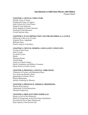
Fundamentals of Liquid Crystal Displays – How They Work and What They DoFundamentals of Liquid Crystal DisplaysBack Lit and Reflective LCDsThe term liquid crystal is used to describe a substance in aLiquid crystal materials emit no light of their own. Small andstate between liquid and solid but which exhibits the propertiesinexpensive LCDs are often reflective, which means if they areof both. Molecules in liquid crystals tend to arrangeto display anything, they must reflect the light from externalthemselves until they all point in the same specific direction.light sources. The numbers in an LCD watch appear where theThis arrangement of molecules enables the medium to flow assmall electrodes charge the liquid crystals and make thea liquid. Depending on the temperature and particular naturecrystals untwist so that the light is not transmitting through theof a substance, liquid crystals can exist in one of severalpolarized film.distinct phases. Liquid crystals in a nematic phase, in whichthere is no spatial ordering of the molecules, for example, areBacklit LCD displays are lit with built-in fluorescent tubesused in LCD technology.above, beside and sometimes behind the LCD. A whitediffusion panel behind the LCD redirects and scatters the lightOne important feature of liquid crystals is the fact that anevenly to ensure a uniform display. On its way through liquidelectrical current affects them. A particular sort of nematiccrystal layers, filters and electrode layers, more than half ofliquid crystal, called twisted nematics (TN), is naturally twisted.this light is lost such as in LCD displays on personalApplying an electric current to these liquid crystals will untwistcomputers.them to varying degrees, depending on the current's voltage.LCDs use these liquid crystals because they react predictablyIn the reflective mode, available light is used to illuminate theto electric current in such a way as to control the passage ofdisplay. This is achieved by combining a reflector with the rearlight.polarizer. It works best in an outdoor or well-lighted officeenvironment. Transmissive LCDs have a transparent rearThe working of a simple LCD is shown in Figure 1. It has apolarizer and do not reflect ambient light. They require amirror (A) in back, which makes it reflective. There is a piecebacklight to be visible. They work best in low-light conditions,of glass (B) with a polarizing film on the bottom side, and awith the backlight on continuously.common electrode plane (C) made of indium-tin oxide on top.A common electrode plane covers the entire area of the LCD.Transflective LCDs are a mixture of the reflective andAbove that is the layer of liquid crystal substance (D). Nexttransmissive types, with the rear polarizer having partialcomes another piece of glass (E) with an electrode in thereflectivity. They are combined with backlight for use in allshape of the rectangle on the bottom and, on top, anothertypes of lighting conditions. The backlight can be left off wherepolarizing film (F), at a right angle to the first one.there is sufficient light, conserving power. In darkerenvironments, the backlight can provide a bright display.The electrode is hooked up to a power source like a battery.When there is no current, light entering through the front of theTransflective LCDs will not “wash out” when operated in directLCD will simply hit the mirror and bounce right back out. Butsunlight. Another feature of the viewing mode is whether thewhen the battery supplies current to the electrodes, the liquidLCD is a positive or negative image. The standard image iscrystals between the common-plane electrode and thepositive, which means a light background with a darkelectrode shaped like a rectangle untwist and block the light incharacter or dot. This works best in reflective or transflectivethat region from passing through. That makes the LCD showmode. A negative image is usually combined with athe rectangle as a black area.transmissive mode.ABCDEFFigure 1Page 3Fujitsu Microelectronics America, Inc.
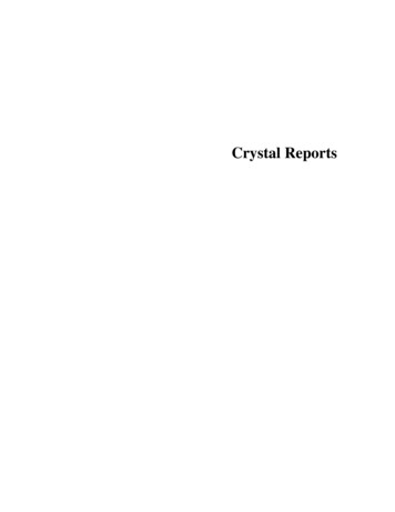
Fundamentals of Liquid Crystal Displays – How They Work and What They DoThis provides a dark background with a light character. Atransparent conductive material. The liquid crystal material isstrong backlight must be used to provide good illumination. Insandwiched between the two glass substrates, and themost graphic applications, the transmissive negative mode ispolarizing film is added to the outer side of each display. Toinverted. This combination provides a light background withturn on a pixel, the integrated circuit sends a charge down thedark characters, which offers the user better readability.correct column of one substrate and a ground activated on thecorrect row of the other. The row and column intersect at aThreshold voltage and sharpness of the response aredesignated pixel, and that delivers the voltage to untwist theimportant parameters to characterize the quality of LCDs. Theliquid crystals at that pixel. As the current required to brightenthreshold voltage, Vth, is the amount of voltage across thea pixel increases (for higher brightness displays) and, as thepixel that is necessary to produce any response whatsoever.display gets larger, this process becomes more difficult sinceSharpness' of the response can be calculated by finding thehigher currents have to flow down the control lines. Also, thedifference in voltage necessary to go from a 10% to a 90%controlling current must be present whenever the pixel isbrightness (usually written as V90–V10).required to light up. As a result, passive matrix displays tend tobe used mainly in applications where inexpensive, simpleAnother characteristic of displays that must be dealt with is thedisplays are required.switching times of the pixels. These are commonly written asTon and Toff, and they correspond to the amount of timeDirect addressing is a technique mostly used in Passive Matrixbetween application/removal of the voltage and a 90%Displays in which there is a direct connection to every elementbrightness/darkness response. Usually Toff, is slightly larger,in the display, which provides direct control over the pixels. Butbecause after voltage is removed, the liquid crystal relaxesdirect addressing is not good in some instances because inback into its off state. No force is being applied, unlike when itlarge displays there can be thousands or even millions ofis being turned on. Switching times can be changed bypixels that require separate connections.controlling the amount of orientational viscosity in the crystal,which is the amount of resistance when being forced toThe method used in the vast majority of large modern displayschange direction.is multiplexing. In this method, all the pixels across each roware connected together on the plate on one side of the liquidThe contrast of a liquid crystal display is an important issue ascrystal film, and all the pixels in each column are connected onwell. One way to measure it is to find the difference inthe opposite side. The rows are then “addressed” serially bybrightness between an on and off pixel, divided by the largersetting all of the column voltages separately for each row andof the two values. A more useful value is the contrast ratio,then turning on the row voltages in sequence.which is simply the larger brightness divided by the smallerbrightness.Significantly fewer physical connections must be made whenmultiplexing is used, but there are also several differentLCD designers want this ratio to be as large as possible inchallenges to address. If there are N rows, as we cycleorder to obtain "blacker blacks"' and "whiter whites." Typicalthrough them, the pixels in one row will only be receiving theLCDs have contrast ratios between 10 and 40. Unfortunately,necessary voltage 1/N of the time. When other rows are beingthe contrast will depend on the angle the display is viewedaddressed, these pixels will be receiving smaller voltagesfrom since the effects of the liquid crystal are calibrated tooriginating only from their column electrodes. Therefore, thework best on light passing through the display perpendicularly.pixels never really receive full on or off voltages. They areWhen viewed from an angle, we are not seeing the lightalways somewhere in between, and depending on how closecoming out perpendicularly from the liquid crystal, so it istogether they are, the contrast of the display can be very low.common to see a breakdown in the contrast. In some cases itis even possible to see a negative image of the display.A simplified scheme of time multiplexing with passive matrixdisplays is shown in Figure 2. The pixels are addressed byTypes of LCDs – Passive Matrixgated AC voltages (only the envelopes are shown) with aThese LCDs use a simple grid to supply the charge tocomplex temporal structure. A short pulse is appliedparticular pixels on the display. Passive Matrix LCDs start withperiodically to the rows as a strobe signal, whereas thetwo glass layers called the substrates. One substrate is givencolumns carry the information signals. A pixel is only selectedrows and the other is given the columns, made from aif a difference in potential (and, therefore, an electrical field) isPage 4Fujitsu Microelectronics America, Inc.
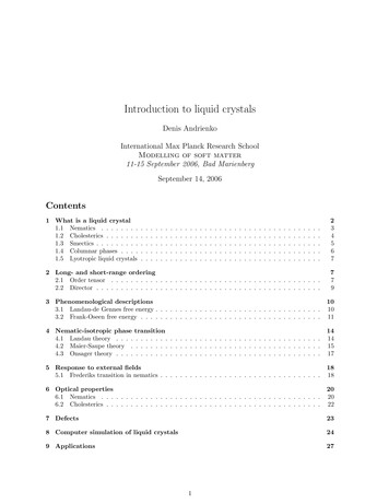
Fundamentals of Liquid Crystal Displays – How They Work and What They DoOFFONRow Signals (Strobe)LCD MatrixColumn Signals (Information)Figure 2present, that is, only if the row and column are not on a low orlight to rotate by a certain angle. The thickness of the film,high level at the same time. More precisely, the pixel istypically around 6 or 8 micrometers, can be controlled toselected if the RMS voltage is above the threshold forproduce a rotation of the polarization of exactly 90 for visiblereorientation.light. Therefore, when the film is placed between crossedpolarizers, this arrangement allows light to pass through.In a passive dual-scan modulator the number of pixel can beHowever, when an electric field is applied across the film, thedoubled without loss in optical contrast by cutting the rowdirector will want to align with the field. The crystal will lose itsstripes in the center of the display and supplying two strobetwisted structure and, consequently, its circular birefringence.signals at each half.Therefore, linearly polarized light entering the crystal will notIn twisted nematic displays the liquid crystal molecules liehave its polarization rotated (in fact, it is only rotated veryparallel to the glass plates, and the glass is specially treatedslightly), so light will not be able to penetrate through the otherso that the crystal is forced to point a particular direction nearpolarizer. When the field is turned off, the crystal will relaxone of the plates and perpendicular to that direction near theback into its twisted structure and light will again be able toother plate. This forces the director to twist by 90 from thepass through. In some displays, the polarizers are parallel toback to the front of the display, forming a helical structureeach other, thus reversing the on and off states. If the lightsimilar to chiral nematic liquid crystals. In fact, some chiralpasses through the two polarized plates, it results in a brightnematic crystal is added to make sure all of the twists go theimage with dark background. However, if light does not passsame direction.through the cross-polarized plates, it results in a dark imagewith bright background. If red-, green-, and blue-colored filtersThe thin film of twisted nematic liquid crystal is circularlyare used on groups of three pixels, color displays can bebirefringent. When linearly polarized light passes through, thecreated. See Figure 3.optical activity of the material causes the polarization of thePage 5Fujitsu Microelectronics America, Inc.
Fundamentals of Liquid Crystal Displays – How They Work and What They DoBrightDarkA4.6µmLEU ( 3V)PFigure 3Twisted nematic displays are simple in architecture, cheap andwas solved in the mid 1980s with the invention of the STNeasy to manufacture. The use of polarizers reduces thedisplay. In this device, the director rotates through an anglepotential brightness since they allow less than half of the lightof 270 , compared with the 90 for the TN cell. The effect ofincident on the display to pass through. The effective viewingtwist angle on the electro-optical response curve is shown inangle of the display can be very small because the opticalFigure 4.activity and the polarizers are tuned to work best only on lightbrightness response curve is often not very sharp, leading toreduced contrast. The display is also affected by crosstalkwhere voltage meant for a certain pixel can leak through"sneak paths'' to nearby pixels, causing a ghosting effect. Andfinally, the switching speed of the liquid crystal is often not ashigh as might be desired – typically around 150 milliseconds.90Mid-layer Tilt Anglethat is propagating perpendicularly to the display. The voltage-603090180Lower switching speeds are necessary when doing00.51.0over the whole scanning cycle to reduce flicker. However, suchapplications (such as full motion video, Passive matrixdisplays are suitable for very low power requirements and onlyalphanumeric data, like watches and calculators.An important consequence of passive time multiplexing is thatthe selection ratio UON/UOFF approaches unity for large pixel2702403003303600multiplexing since we want the crystal to respond to voltageslow speeds make passive matrix displays unusable for many2101.52.02.53.0VoltageFigure 4Note that the change in the tilt angle becomes very abrupt asthe twist angle is increased. The consequence of thisresponse curve is that the off and on voltages are closertogether, as shown in Figure 5.numbers as required with standard VGA computer displays or50electro-optical characteristics are required to achieve sufficientoptical contrast with weak selection ratios. This was thereason for the development of TN-modulators with larger twistangles than 90 , so-called Super-Twisted-Nematic or STNmodulators.The difference between the ON and OFF voltages in displayswith many rows and columns can be very small. For thisTransmission (%)better. Therefore, liquid crystal modulators with rather steep403090%20100.00.0Page 61.02.03.0Voltagereason, the TN device is impractical for large informationdisplays with conventional addressing schemes. This problem100%Figure 5Fujitsu Microelectronics America, Inc.
Fundamentals of Liquid Crystal Displays – How They Work and What They DoAlthough it is desirable to obtain a sharp electro-opticresolution, and daylight readability, providing more informationtransition, grayscale images require intermediate points alongcontent than monochrome displays.the curve. For this reason, many commercial STN displaysuse a twist angle of 210 . This broadens the transition regionDesign is generally customized for the requirements of aenough for grayscale while allowing for conventionalspecific application, so CSTN LCDs are not available as aaddressing. STN displays make use of color filters to come upstandard product. High NRE charges are involved with largewith color STN displays.volumes.Using STN technology, displays with a better contrast ratio areThese displays are best for graphics applications includingproduced. STN displays can go up to a higher resolution ofconsumer electronics such as handheld devices, TV screens,about 500 rows. STN displays also result in wider viewingcomputer monitors and digital cameras. It was discovered thatangles, high-quality colors and a higher number of gray scaleplacing a second layer of STN LCs above the first, with thelevels as compared to TN displays.STN chains twisted in the opposite direction, produces a trueblack and white image. The addition of colored filters to theseTheir response time (the time it takes to go from on to off or offallows a color display to be produced. This type of display withto on) is slower than TNLCs, about 200 milliseconds asthe double layer of STN LCs was given the name "doubleopposed to about 60 milliseconds. Also, STN displays are notsuper twisted nematic LCD" or DSTN LCD. DSTN displays areas bright and are more expensive to manufacture. Anotheractually two distinct STN-filled glass cells glued together. Thedisadvantage of early STN LCDs was that they tended tofirst is an LCD display; the second is a glass cell withoutproduce blue and yellow images, rather than black and whiteelectrodes or polarizers filled with LC material for use as aones, due to a small difference in ON and OFF voltages. Socompensator, which increases the contrast and delivers theSTN displays are ideal for regular graphics applicationsblack-on-white appearance.including consumer electronics products like handhelddevices, TV screens, computer monitors and digital cameras.This DSTN LCD has a better contrast ratio than STN, andoffers automatic contrast compensation with temperature.A color STN display has the ability to show full-color characterResponse time is significantly enhanced. The DSTN LCDthrough standard passive matrix LCD technology. Similar to areduces the tendency of a screen to become slightly red,monochrome LCD, color displays consist of front and reargreen or blue and has viewing angles wide enough for 6glass panels, polarizers, glass panels, retardation films ando’clock and 12 o’clock directions. Operating temperatures fromindium tin oxide (ITO). The main differences between passive-30 C to 80 C are supported. The storage temperature rangecolor cell and monochrome cell is that the segment ITO is nowis -40 C to 90 C.separated into three colors, RGB, and the transflective layer ismoved internally or inside of the glass panels. In addition toOne drawback, despite the performance, is that these displaysthese slight changes, a color filter is embedded in the cell toare much thicker, heavier and more expensive to manufacture.make it a full-color display solution. The color filter isHowever, they are definitely suitable for use in automobiles,comprised of red, green and blue pigment and is aligned withindustrial facilities and gasoline pumps.a particular sub-pixel within the cell.As its name suggests, FSTN (Film Compensated SuperThree of these sub-pixels – one each for red, green and blue,Twisted Nematic) uses an additional optical film tocombine to make one full-color pixel in a display. In eachcompensate for the color effect found in super twisted nematicsub-pixel, the color filter transmits only the polarized light ofdisplays. With a neutral background and virtually a black/darkthat sub-pixel’s color. Through the use of LCD shading forgray "ON" segment color, the display gives a comfortableeach, a large number of unique colors can be displayed."paper feel" viewing.So a 320 x 240 pixel CSTN display actually contains960 x 240 individually colored pixels.With true black-and-white display characteristics, exceptionalquality, enhanced visibility in dark and bright conditions, and aThese displays are cost-effective compared with color thin filmwide range of operating temperature, FSTN is an excellenttransistor (TFT) displays, with low power, full-color displaychoice for high-value handheld devices, navigation equipmentsuch GPS, mobile phones, or mono-color PDAs.Page 7Fujitsu Microelectronics America, Inc.
Fundamentals of Liquid Crystal Displays – How They Work and What They DoActive Matrix or TFT (Thin Film Transistor) LCDsthere is a liability of a couple of defective pixels where theActive matrix displays belong to type of flat-panel display intransistors have failed.which the screen is refreshed more frequently than inconventional passive-matrix displays, and which usesTwo phenomena define a defective LCD pixel.individual transistors to control the charges on each cell in theliquid-crystal layer. The most common type of active-matrixFirst is a "lit" pixel, which appears as one or several randomlydisplay is based on the TFT technology. The two terms, activeplaced red, blue and/or green pixel elements on an all-blackmatrix and TFT, are often used interchangeably. Whereas abackground, or a "missing" or "dead" pixel, which appears as apassive matrix display uses a simple conductive grid to deliverblack dot on all-white backgrounds. The former is the morecurrent to the liquid crystals in the target area, an active matrixcommon and is the result of a transistor occasionally shortingdisplay uses a grid of transistors with the ability to hold aon, resulting in a permanently "turned-on" (red, green or blue)charge for a limited period of time, much like a capacitor.pixel. Unfortunately, fixing the transistor itself is not possibleBecause of the switching action of transistors, only the desiredafter assembly. It is possible to disable an offending transistorpixel receives a charge, improving image quality over ausing a laser. However, this just creates black dots, whichpassive matrix. Because of the thin film transistor's ability towould appear on a white background. Permanently turned-onhold a charge, the pixel remains active until the next refresh.pixels are fairly common occurrences in LCD manufacturingand LCD manufacturers set limits – based on user feedbackThere are three main switch technologies of TFTs: amorphousand manufacturing cost data – as to how many defective pixelssilicon (a-Si), polycrystalline silicon (p-Si), and single crystalare acceptable for a given LCD panel. The goal in settingsilicon (x-Si). The silicon transistor matrix in a TFT is typicallythese limits is to maintain reasonable product pricing whilecomposed of amorphous silicon (a-Si). Amorphous siliconminimizing the degree of user distraction from defective pixels.TFT LCDs have become the standard for mass-producedFor example, consider a 1024 x 768 native resolution panel,AMLCDs. They have good color, good greyscale reproduction,containing a total of 2,359,296 (1024 x 768 x 3) pixels. If it hasand fast response.just 20 defective pixels, the pixel defect rate is measured as(20/2,359,296) x 100 0.0008%.Because a-Si has inherently low mobility (area/voltageseconds), usually a capacitor must be added at each pixel.These are thinner and lighter displays as compared to passiveThe a-Si TFT production process takes only four basicmatrix LCDs, have faster response times than STN and DSTNlithography steps, and can have good quality displays up todisplays, can support higher resolutions, have higher contrast14". For color TFT displays, there is one transistor for eachratios with wider viewing angles, have high-quality colors, andcolor (RGB) of each pixel. These transistors drive the pixels,low power consumption. But they are also expensive, showeliminating at a single stroke the problems of ghosting andlower yield rates, and have a higher probability of defectiveslow response speed that affect non-TFT LCDs. The result ispixels.screen response times of the order of 25ms, contrast ratios inthe region of 200:1 to 400:1, and brightness values betweenApplications include high-resolution displays, laptop200 and 250cd/m2 (candela per square meter).computers, HDTV, healthcare equipment, along with militaryand industrial applications where high reliability and qualityTFT screens can be made much thinner than LCDs, makingare required.them lighter, and refresh rates now approach those of CRTsas the current runs about ten times faster than on a DSTNFuture Trendsscreen. VGA screens need 921,000 transistors (640 x 480 xOLED (Organic Light Emitting Diode) Displays3), while a resolution of 1024 x 768 needs 2,359,296Organic light emitting diode (OLED) technology usestransistors and each has to be perfect. The complete matrix ofsubstances that emit red, green, blue or white light. Withouttransistors has to be produced on a single, expensive siliconany other source of illumination, OLED materials presentwafer and the presence of more than a couple of impuritiesbright, clear video and images that are easy to see at almostmeans that the whole wafer must be discarded. This leads to aany angle. OLED displays stack up several thin layers ofhigh throwaway rate and is the main reason for the high pricematerials. The displays comprise of dielectric light-emittingof TFT displays. It's also the reason why in any TFT displayphosphor layers sandwiched between two conductivePage 8Fujitsu Microelectronics America, Inc.
Fundamentals of Liquid Crystal Displays – How They Work and What They Dosurfaces. During manufacturing, multiple organic layers areBright, crisp images and video are easy to see from any anglelaminated onto the stripes of optically transparent inorganicowing to the display's unsurpassed contrast and luminance.electrodes. The organic layers comprise of an electronOLED screens appear extraordinarily bright because of theirtransport layer (ETL) and a hole transport layer (HTL). Theunusually high contrast. Unlike LCDs, they have neitherlayers operate on the attraction between positively andbacklights nor chemical shutters that must open and close.negatively charged particles. When voltage is applied, oneInstead each pixel illuminates like a light bulb.layer becomes negatively charged relative to anothertransparent layer. As energy passes from the negativelyClear, distinct images result from the OLED displays’ lifelikecharged (cathode or ETL) layer to the other (anode or HTL)color reproduction, vibrancy, and brightness. Unlike LCDs,layer, it stimulates organic material between the two, whichOLED screens dispense with intervening liquid crystalemits light visible through the outermost layer of glass.structures that limit color vibrancy off-angle. OLED pixels turnon and off as fast as any light bulb. Their independent action inDoping or enhancing organic material helps control thean active OLED display produces fluid full-motion video. Inbrightness and color of light. And manufacturers can choosefact, active displays can refresh at rates more than three timesorganic materials’ structure – “small” (single) molecules orthat required for standard video.complex chains of molecules (polymers) – to best suitproduction facilities.Thin OLED screens are free from the added bulk and weightof backlighting, making them ideal for compact devices. EasierActive matrix and passive matrix screens are two fundamentalto see in changing ambient light conditions, OLED displaystypes of OLED display assembly. Each type lends itself tobring an edge to device ergonomics. Bright, clear images anddifferent applications.a faster pixel refresh rate – easily better than the standard60 frames per second – mean fewer compromises in deviceActive matrix OLED displays stack cathode, organic, anddesign and use. OLED displays are more easily viewed thananode layers on top of another layer – or substrate – thatLCDs of comparable size, providing greater utility. You nocontains circuitry. The pixels are defined by the deposition oflonger need to position yourself or your device to get a goodthe organic material in a continuous, discrete “dot” pattern.view.Each pixel is activated directly: A corresponding circuitdelivers voltage to the cathode and anode materials,OLED panels take the same input signals as LCDs, so it isstimulating the middle organic layer.possible to add value to existing product designs and createnew ones. The panels are also not power hungry. In typicalAM OLED pixels turn on and off more than three times fasterimage and video applications, OLED displays typically usethan the speed of conventio
Fundamentals of Liquid Crystal Displays - How They Work and What They Do Page 2 Fujitsu Microelectronics America, Inc. Liquid crystal display technology has enjoyed significant advances in just a few short years.