Transcription
OFC 2005TutorialCurrent Trends in Optical MEMSMing C. WuUniversity of California, BerkeleyEECS Department &Berkeley Sensor and Actuator Center (BSAC)wu@eecs.berkeley.eduMing Wu @ OFC 20051
Acknowledgment Providing viewgraphs––––––––Thomas Ducellier (Metconnex)Li Fan (Formfactor)Andres Fernandez (Glimmerglass)Roger Helkey, Olivier Jerphagnon (Calient)Dan Marom (Lucent)Katsu Okamoto (Okamoto Lab)Olav Solgaard (Stanford University)Rod Tucker (Univ. Melborne) Graduate students and Postdocs at Berkeley and UCLA––––WSS: J.C. “Ted” Tsai, Dooyoung Hah, Sophia HuangPhC switch: M.C. “Mark” LeeMEMS Microdisk: M.C. “Mark” Lee, Jin YaoMEMS PLC switch: Josh C.H. Chi, Jin YaoMing Wu @ OFC 20052
OUTLINE Introduction Optical design considerations Space division switches– 2D MEMS optical switches– 3D MEMS optical switches Spectral domain processors– Wavelength-selective switches Planar lightwave circuits (PLC)-MEMS Integration Diffractive optical MEMS New directions SummaryMing Wu @ OFC 20053
25 Years of Optical MEMSScanning Mirror(Petersen, IBM)Micromotoers(Berkeley)1980Digital MicromirrorDevice (DMD, TI)TI’sTI DMDMing Wu @ OFC 2005Free-Space Optical Bench(UCLA/Berkeley)19903D MEMSSwitches2000Grating Light Valve(GLV, Stanford)Silicon Light Machine42D MEMS Switches(Tokyo U)?
Bulk Micromachining Anisotropic wet chemical etching (restricted to fixed crystalline orientations) 100 110 111 111 VerticalSidewall Deep reactive ion etching (DRIE or ICP-RIE) Combine with silicon-on-insulator (SOI)or III-V epi wafer High aspect ratio ( 20:1) Independent of crystal orientation More efficient use of real estate ofsubstrate (e.g., can produceclosely spaced structures)Ming Wu @ OFC 2005 Suspended structure in one-stepetching releasing Multi-layer structure by additional waferbonding5
Surface-Micromachining:2 “Standard” Foundry ProcessMUMPsMUMPsSUMMiTSUMMiT1 um12.75 um0.5 umPoly 42 umPoly 36.25 umCMP1Poly 2Poly 2Poly 1Poly 1Poly 0Poly 0Si SubstrateSi Substrate Sandia National Lab MEMSCAP Fairchild (SUMMiT-4)Ming Wu @ OFC 2005CMP26
MEMS Technologies and Optical Element Size1 cm1 mm100 µm10 µm1 µmOpticalElementSizeScanning iesMainActuationMechanismsMing Wu @ OFC WSS2D Gain equalizer 2x2 SwitchesMEMS DispersionVOASwitch ce-Micromachining(Single Crystalline Si,DRIE, Wafer Bonding)(Poly-Si, Al)ElectromagneticActuationElectrostatic Actuation7MicroresonatorsPhotonicCrystals
Optical DesignsMing Wu @ OFC 20058
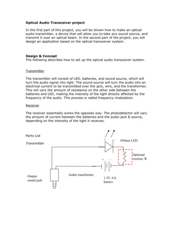
Direct Coupling Without Lenses0dThermally Expanded Core(TEC) FiberInsertion Loss (dB)Single Mode Fiber 00600Distance (um) Short propagation distance May be used for small switches or VOAsMing Wu @ OFC 200598001000
Example: 2x2 SwitchCrossStateBarStateMarxer, et al., J-MEMS, vol.6, 1997. p.277-85.Ming Wu @ OFC 200510
Free-Space Optics: Gaussian Beam2 2w02w0bπwb λ2 z 22w ( z ) w0 1 b 20 Larger beam waist Æ Long collimation length System size 2b Mirror diameter 2aw0,Ming Wu @ OFC 2005a 1.5 to 211(Confocal Parameter)
Space Division Switches:(1) 2D MEMS Optical Switches(2) 3D MEMS Optical SwitchesMing Wu @ OFC 200512
Scaling of 2D MEMS Optical Switches2 2 w02w0“ADD” Channels2D MEMSSwitchChip2b“DROP”ChannelsN : Port CountP : Fiber PitchInputChannelsL NP 2b CollimatorArraysOutputChannelsλ: Chip Length2R: Fill Factor of Micromirrorη PR aw0 : Mirror Radius (vertical)Pa 2L 2bπη N w0aλMing Wu @ OFC 20052πw0213 2a 2 λ 2 NL 2 πη
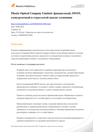
Port Count of 2D MEMS SwitchesPort Count vs Beam SizeLoss Due to Mirror Tilt5LossdueTilt(dB)LossduetotoMirrorMirror Tilt(dB)MaximumCountMaximumPortPort Count80Fill Factor 70%6050%4030%200Mirror Tilt 40.2 320.1 10.05 00501001502000Beam Waist(µm)1/e21/eBeamWaist(µm)πηw0aλ 2a 2 λ 2 NL 2 πη Port Count : N Chip Size :Ming Wu @ OFC 2005 14501001501/e21/eBeamWaist(µm)(µm)Beam Waist200Accuracy and uniformity of mirrorangles impose a loss penalty, whichlimit the maximum port count
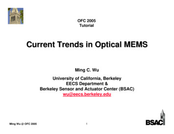
Surface-Micromachined2D MEMS Optical Switches (16x16)L. Fan, et al., OFC 200216x16 SwitchL. Fan, et al., OFC 2002Absolute angular uniformity 0.05 70Number6050403020Ming Wu @ OFC 200515Mirror Angle .8889.84089.8010
Scaling of 3D MEMS OXC2D Array of s2D Array of 2-AxisMicromirrors2πL( θ )2Port Count : N 9a 2 λL 3a 2 λ NSystem size 2 3 π ( θ ) 2w02w0Optical Path Length : L 2b 2πw02λ θ : Mechanical Scan Angle Ming Wu @ OFC 2005L3R aw0 : Mirror Radius (a 2)16w0 : Beam Waist
3D-MEMS Switching TechnologyASIC Voltage driversMEMS mirror 020%10%00%0Collimator arrayCumulative PercentageNumber of Connections320x320 connections below 3.5 dB0.511.522.533.54Insertion Loss (dB)Typical Wavelength Dependent LossTransparentnmTransparent fromfrom 1260-16251260 to 1625nmInsertion Loss (dB)Note: the higher loss peak around 1400 nm is due to OH water absortion and can vary.Evolutionary y Technology17LPX13001350140014501500Wavelength (nm)Calient Network proprietary and confidential. Do not copyor distributepermissionMingWuwithout@ OFC2005C155016001650
Glimmerglass 3D-MEMS SwitchesCollimatorArrayMEMSMirror Array3D-MEMS Architecture2” x 6” x 7”32x32 to 80x80 OEM Module Glimmerglass 200516x16 to 24x24 2U Chassis32x32 to 160x160 8U Chassis
Glimmerglass MEMS Module(Scan Angle 3.5º @ 200V)SPIE Vol. 5604, pp. 208-217Gimbaled MirrorSnap Guard WaferMirror WaferVMulti-Layer CeramicElectrostatic Actuation Electrode Snap Guard Prevents Electrostatic Snap-Down Failure Mirror Material Is Highly Reliable Single-Crystal Silicon on Insulator (SOI) Ceramic Substrate Contains Electrodes, Routing, And Hermetic Seal Ring Glimmerglass 2005
Wavelength-Selective Switches (WSS)Ming Wu @ OFC 200520
Fourier Transform Pulse ShaperA. M. Weiner, J. P. Heritage, and E. M. Kirschner, J. Opt. Soc. Am. 1988 Shaping femtosecond pulses by modulating the phases andamplitudes of their spectral componentsMing Wu @ OFC 200521
Dynamic WDM FunctionsCorstaollimMLi EMgh StM SAr od patra ul ialy atorgit narGffMing Wu @ OFC 200522MEMS SpatialLight ModulatorArrayDynamicWDMFunctionsPiston MirrorsFemtosecond lereflectivitymirrorSpectral (or gain)equalizer1x2 DigitalmicromirrorsOptical add-dropmultiplexer (OADM)1xN analogmicromirrorsWavelengthSelective Switch(WSS)DeformablemirrorsTunable dispersioncompensator
1x4 Wavelength-Selective Switch (WSS)YorstalimloCXgit narGAnalogMicromirrorArrayffMing Wu @ OFC 200523
1x4 WSS D. Marom et al. (Lucent), OFC 2002– 1x4 WSS– Channel spacing: 50 or 100 GHz– MEMS performance: 12 ( 55 V )Ming Wu @ OFC 2005 T. Ducellier et al. (JDS-U),ECOC 2002– 1x4 WSS– Channel spacing: 100 GHz– MEMS performance: 2 24
64 Channel, Wavelength-Selective 4 1 Switch (D. Marom)Free-Space ImplementationWSS provides: Port switching Wide passbands 10 dB DSE Blocking Low insert loss Low PDL, DGDMing Wu @ OFC 200525
Analog Micromirror Array (UCLA)Movable fingersMirrorzyxHidden springsRotation Angle (deg)Fixed fingers8AnchorComb Finger Spacing0.5µm 1µmScan Angles2µm63µm42DMD-Like005101520Applied Voltage (V)Ming Wu @ OFC 200525 /- 6 (mechanical)Voltage6VFill Factor98%Res. Freq.3.4 kHzStability (3hr) 0.00085 System (3hr) 0.0035dB Hah, et al (UCLA) J. MEMS, 2004, p. 279 Tsai, et al (UCLA) IEEE PTL 2004, p. 104126
Scaling of WSSwCollw MEMSAnalogMicromirrorArrayCollimatorsffw MEMS N spatial λλ fπ wCollπf θ 22λ f # λ Grating System size 2 fπ BWλ f θ N spatial N λ 22λ f # λ GratingMing Wu @ OFC 200527 Total capacity (Nspatial x Nλ )is constant– Proportional to f
Approach for Increasing Port Count (1)D. Marom(Lucent) Use anamorphic prism pair to compress lateral beam size onMEMS micromirrors Elliptical beams on MEMS mirrors Æ RectangularmicromirrorMing Wu @ OFC 200528
Approach for Increasing Port Count (2)Y 1xN2 WSS:– 2D collimator array– 1D array of 2-axismicromirror arrayXGrating Port count is increasedfrom N to N2– N is the diffraction-limitedlinear port count High port count WSS– 1x32 WSS has beendemonstratedfResolution lensMing Wu @ OFC 2005 J.-C. Tsai, et al., (UCLA) ECOC 2004,Paper Tu1.5.2f29
High-Fill Factor 2-Axis Micromirror ArrayMirrorLever2-DOF mirror jointVerticalcombdriveactuators Gimbal-less– High Fill factor ( 98%) Large scan angle– 3x leverage– Powerful vertical combdriveactuatorsyTsai, Fan, Hah, Wu, Optical MEMS 2004Ming Wu @ OFC 200530xOriginal mirrorposition
SEM of Gimbal-less 2-Axis Analog MicromirrorArray SUMMiT-V 5-layer surface micromachining process Mirror pitch: 200 um Large scan angles: 6.7º (mechanically) @ 75 V Fill factor: 98% Resonant frequency 5.9 kHzMing Wu @ OFC 200531
Planar Lightwave Circuit (PLC) MEMSMing Wu @ OFC 200532
Reconfigurable Optical Add/Drop Multiplexer(ROADM)Drop Main outputport portMain Addinput portport(a) Configuration of 16ch-100GHz OADM(b) Photograph of OADMK. Okamoto et al., Electron. Lett., vol. 31, pp.723-724, 1995(VG courtesy of K. Okamoto)Ming Wu @ OFC 200533
PLC 1x9 WSSOutput 1Output 21x2Output 3Output 4Input 1x9 WSS Thermal optic switch– 450 mW / switch– Total power 14W Loss 5.4 dB Isolation 46 dBOutput 5C.R. Doerr, et al. (Lucent), OFC 2002 Postdeadline Paper, FA3Ming Wu @ OFC 200534
2x2 MEMS Waveguide WSXC 3 diffraction orders by AWG Optical phases of ( 1, 0, -1) ordersmodulated by MEMS piston mirrors Chip 5 x 9 mm2D.T. Fuchs, et al (Lucent) IEEE PTL, Jan. 2004Ming Wu @ OFC 200535 100 GHz channel spacing 10.6 dB insertion loss 20 dB extinction ratio
40 Channel, Wavelength-Selective 1 2 Switch (D. Marom)Hybrid PLC and Free-Space ImplementationInputλ λ0PLC 1 and PLC 2MEMSmicromirrorarrayPort 1Port 2Hybrid WSS provides: Same benefits as free space WSS Compact implementation Integration of additional functionalityCylindricalcollimatorsSwitch to Port 1Ming Wu @ OFC 200536Fourierlensλ0λ λ0Switch to Port 2
Compact Spectral Pulse Shaper (D. Marom)Hybrid PLC and Free-Space Implementation3.0Phase [π]2.52.01.51.00.50.0020406080VoltageInput PulseThru shaperDispersionCompensated Shaped signalMEMS piston motion micromirror array 2π phase modulation Polarization insensitiveMing Wu @ OFC 200537Pulse Shaper provides: Spectral domain processing Polarization independent Gateway to optical arbitrarywaveform synthesis
2D arrangement of ports for scalable 1x9WSSArray of Waveguide Dispersive ElementsCollimating/FocusinglensesMEMS mirrorlinear arrayMing Wu @ OFC 200538
Interleaved spectrum switched to alloutput portsMing Wu @ OFC 200539
1x8 PLC MEMS Optical Switches4.5 mmFiberRibbonMicromirrorFan-ShapedWaveguide ArrayLow-LossButt CouplingFree PropagationSlab Region3 mm Theoretical loss 0.5 dB, primarilySlabdueto vertical diffraction lossDeep-EtchedCylindricalMicrolensCladdingCore Compact, no bulk optical elementsCladdingC.H. Chi, et al. (UCLA and Okamoto Lab), OFC 2004Ming Wu @ OFC 20054050 um
Tunable Fabry-Perot FiltersMing Wu @ OFC 200541
Tunable Fabry-Perot (FP) Filters fFreeSpectralRange(FSR)Transmissiondf 3 dB SR (in freq.) (in wavelengt h)2d2dFor d 3λResonance Condition :FSR 260 nm Broadly Tunablef 2kd m 2π 2 2π d m 2π fGHzc 40 Efficient Tuning dnmfc f d ddλdMing Wu @ OFC 200542
Tunable FP Filters Has been demonstrated in many material systems– III-V– Dielectric (e.g., Si/SiO2)– Semiconductor – Air gap DBR Various actuation mechanisms– Electrostatic (parallel plate actuators)– Thermal actuators– Piezoelectric actuatorsMing Wu @ OFC 200543
Nonlinear Optical ResponseOpticalPowerData supplied by CoreTekVG courtesy of Prof. Rod Tucker (Univ. Melbourne)Ming Wu @ OFC 200544
Effective Spring Constant due toRadiation PressureFEPoutFR 2 Pout(1 R ) cPoutλk effFE4P FSR dG k in λc (1 R ) dfkxKeff xPoutFilter Response SlopeMing Wu @ OFC 2005VG courtesy of Prof.Rod Tucker (Univ. Melbourne)45
Diffractive Optical MEMSMing Wu @ OFC 200546
Grating Light ValveIncident Light ReflectedIncident Light DiffractedNitride withAl coatingO. Solgaard, F. S. A. Sandejas, D. M. Bloom, "A deformable grating optical modulator", OpticsLetters, vol. 17, no. 9, pp. 688-690, 1 May 1992. Applications––––Projection displayVariable optical attenuators (VOA)Gain equalizersWavelength blockers Companies– Silicon light machine (Cypress),Lightconnect, Polychromix, KodakMing Wu @ OFC 2005Silicon Light Machine47Polychromix
Telecommunications ApplicationsDynamic Spectral Equalizer (DSE)Reconfigurable Channel Blocking FilterMing Wu @ OFC 2005Dynamic Gain Equalizer48
MEMS Switchable WDM Deinterleaver Based onGires-Tournois InterferometerOlav Solgaard, Stanford UniversityInput ectorMEMS BeamFocusingMirror SplitterLensArrayMing Wu @ OFC 2005OutputFiber Arrayhttp://wdm.stanford.edu/snrc/kyoungsik12 10 01.ppt49
Nanophotonic MEMSMing Wu @ OFC 200550
1D and 2D Photonic Crystal Switches1D Photonic Crystal:ON-OFF Switch2D Photonic Crystal:1x2 Switch(Æ NxN Switch)ONOFFLeft PathWaveguideDefectWaveguideMing Wu @ OFC 200551Right Path
Transmittance1D MEMS Photonic SwitchReflectionStateTransfer MatrixFDTDTransmittanceWavelength (μ m)TransmissionStateTransfer MatrixFDTDWavelength (μ m)Ming Wu @ OFC 200552
Experimental ResultsAnchorWaveguide(WG)PC SliderTransmittance G)LightwaveWavelength (μ m) 100-nm-wide beam with 5 nmtolerance ON-OFF switching with 11 dBextinction ratio 0.5 ms switching timeM.C. Lee, et al (UCLA) OFC 2002Ming Wu @ OFC 200553
Microring Resonator-Based PIC42 µmThermally Tunedwith Vernier ArchitectureS. T. Chu, B. E. Little, V. Van, J. V. Hryniewicz, P. P. Absil, F. G. Johnson, D. Gill, O. King,F. Seiferth, M. Trakalo and J. Shanton (Little Optics) OFC 2004Ming Wu @ OFC 200554
MEMS Tunable MicroresonatorsFabry-Perot ResonatorsMicrodisk Resonatorsλ0InputInputDropλ0Dropλ0 Change resonant wavelength Change resonant wavelength– Thermal tuning– Free-carrier injection– Move mirror Change effective Q Change effective Q– Increase cavity loss (e.g.,electroabsorption)– Change waveguide-disk couplingMing Wu @ OFC 200555– Increase media loss– Tune mirror reflectivity (Hard)
Microdisk Resonator with MEMS odiskVVM.C.M. Lee and M.C. Wu, Optical MEMS 2003Ming Wu @ OFC 200556
Dynamic Optical Add-Drop roughPortDropPort0.40.2Add000.20.40.6Gap Spacing (um)Ming Wu @ OFC 2005570.8
Spoiling Q by MEMS Metal Membrane Use a metal membrane to spoil the Q of microring resonator– Low loss Æ resonant wavelength sent to “Drop” port– High loss Æ all wavelengths transmitted to “Through” portDisabled resonanceEnable resonanceGregory N. Nielson, et al., (MIT) “MEMS based wavelength selective optical switching forintegrated photonic circuits”, CLEO 2004Ming Wu @ OFC 200558
SUMMARY Tremendous progresses have been made in––––MEMS devices and manufacturingMicro-opticsPackagingControl New trends in Optical MEMS -- Integration–––––Higher level of integration, less free-space alignmentMEMS-PLC integrationMEMS-nanophotonics integrationElectronics integrationSingle-chip optical MEMS systemMing Wu @ OFC 200559
Mirror Tilt 0.05 0.1 0.2 Port Count vs Beam Size Loss Due to Mirror Tilt Accuracy and uniformity of mirror angles impose a loss penalty, which 2 limit the maximum port count 2 2 0 2 N a L w a N πη λ λ πη Chip Size: Port Count: 1/e2 Beam Waist (µm) 1/e2 Beam Waist (µm) Maximum Port Count .