Transcription
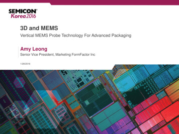
3D and MEMSVertical MEMS Probe Technology For Advanced PackagingAmy LeongSenior Vice President, Marketing FormFactor Inc1/28/2016
Agenda/Outlines Rapid recent adoption of advanced packaging– Copper pillar and 2.5D/3D ICs– Customers relying on “more-than-Moore” advances Presents significant challenges for wafer test and probe– Layouts are fully-populated 2-D arrays at 100um pitch– Contacts are delicate structures made of new and diverse materials– Industry requires a “Moore-like” cost and time-to-volume trajectory Solutions rely on a synthesis of technologies from diverse areas– MEMS processes, materials science, automation, etc.2
Transistor Scaling and Cost Reduction Trajectory Slowing“More-Than-Moore” Advanced Packaging Accelerating Below 10nmI/Os per cm220,000Flip Chip3D/2.5DTechnologyAccelerating10,000Leading EdgeFinFET1500500Wire Bonding906540282014 10Tech Node (nm)3
2.5D IC and 3D IC Technologies are growing2.5D/3D IC Package Production Forecast, Units, MillionsCAGR3D IC Memory and Logic3D IC Memory2.5DSource: Gartner, New Venture Research, McKinsey4
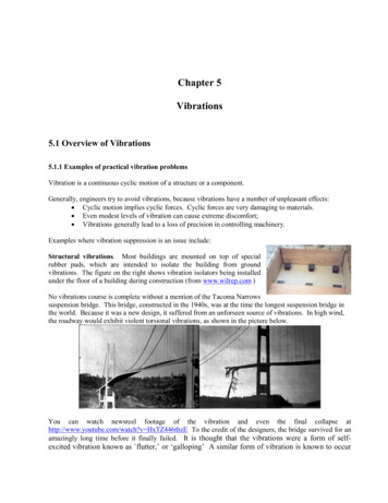
3D IC/2.5D Silicon Interposer Application & Device DriversCu Pillar Enables 3D Fine-pitch Memory Interface and 2.5D Silicon Interposer High-end Applications––––ServersHigh-end computingData centerGame consoles Devices– FPGA– High-end Memory HBM Wide I/O HMC– GPUs– CPUsSamsung DDR4 3DDRAM ModuleNvidia PascalGraphic ModuleIntel “Knight Landing”Using HMC5
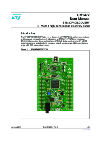
Wafer Probing ChallengingSmaller Cu Pillars at Finer Pitch Require High Contact Precision and Low ForceSolderBumpCu Pillar Dimension RoadmapPitch (um)150um130um100um80um60um40umDiameter (um)80 um60-70um40-50um25-30um20-25um20-25 umHeight (um)80 um75 um60 um50 um40 um35 um80um25 umSubstrateSubstrateSolder BumpCu Pillar*Source: FFI Estimate, 20156
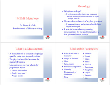
Cu Pillar Probe Mark Photo GalleryNo PassMisaligned Probe TipPassGood Probe Mark on30um Cu PillarNo PassCu Pillars with ShearedSolder CapNo PassProbe force too high7
Mechanically Formed Vertical Probes Give Way to MEMsProbes Below 100um Pitch Mechanical Tolerances for Stamped probes are inferior to MEMs structures Guide Plate Mechanical Drilling is Inferior to MEMs Guide Plate FormationTechnology Tip Geometries are Poorly Controlled by Stamping and Forming Versus MEMsfabrication Contact Materials are Limited to Bulk Alloys for Mechanical Probes but are ByDesign for MEMs probes. Stable Contact at Low Probe Forces is Enabled by MEMs contact DesignFormFactor80um PitchGrid-arrayMEMS ProbeFormFactor40um PitchGrid-arrayMEMS Probe8
Dimensional Control Improved With MEMSBased Fabrication ProcessesMechanically FormedMEMS Fabbed Raw “as-fabbed”distributions Indicative ofnatural processcapability9
For Sub-100um Pitches, MEMS-based DimensionalControl Offers Significant AdvantagesReduction in as-produced dimensional errors can be used in different ways– Larger probe for a given design pitch - for 80um example above, D 25um Better electrical performance (current, impedance) and longer lifetime– Smaller minimum-viable pitch for a given probe Improved design coverage and extendibility– Higher probe/GP component yield for cost reduction10
Composite MEMS Structure Helps to Carry MoreCurrent Through An Ever-Shrinking Probe Cross-SectionFormFactor Composite MEMs Probe Geometries are getting smaller, while current densities are increasing Composite MEMS probes made from different material– Analogous approach to composite design in other fields (eg, aerospace)– Broad material set for best mechanical and electrical performance11
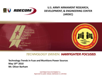
Maximum Allowable Current (MAC) vs Current Carrying Capability (CCC)MAC to CCC Ratio is not constant, is probe architecture dependent*Current Capability (A)1.21MAC represents actual current thatprobe can safely deliver, a morereliable specification than CCC *Current Carrying Capability (A)Max Allowable Current (A)0.80.60.40.2Grid-array Pitch (um)0160135100Vertical3.5milVertical3 milMEMSProbe 180MEMSProbe 2Source: “Determining Probe’s Maximum AllowableCurrent”, Kister et al, SWTW 2015Probe Technology12
These 2-D Layouts are Populated With Structures ThatRequire Low Probe Forces Typical SnAg damage (d) requirement 50% of pillar diameter (D)– Additional requirements on probe mark topology (notching, smearing, etc.)– Imposed by assembly constraints (reliability)– Met with probe forces of 2-3g for 30um D 40um13
At Low Force, Probe Material and GeometryOptimization Required for Stable Electrical ContactSource: Data from Wittig et al, SWTW 201114
There are More and More of These Probes in Each CardProbe per card(Normalized to Q4’2014)32.521.51Q4'2014Q1'2015Q2'2015Q3'2015 Two primary drivers/causes (roughly equal influences)1. Increased parallelism – more DUTs for test cost reduction2. Increased probes per DUT – more test content and complexity per DUT15
Probe Assembly Throughput Is Becoming An Issue forProbe Card Cycle-time @ 80um CuP PitchVertical Probe Assembly ThroughputDecreases with Slimmer ProbesProbe Head Assembly Is Becoming the CriticalPath to Probe Card Cycle-time As PinCounts/Probe Card Approaches 20k Pins18001600140012005010008006004002000180 um150 um100 umPitch (um)80 umShifts to Assembly A Probe HeadTypical Manual Probe Head ASsemblyThroughput (Probes/Shift)200045403530Custom SubstrateTypical FabCycle-time180 um25150 um20100 um1580 um105010,00020,000Probes per Card30,00016
Time-to-Volume Ramp-up @ 80um CuP PitchConcurrent Assembler ShiftsWhat if 5 or 10 cards are needed in a week to address peak demand?100908070605040302010-With manual probe head assembly, toship 10 units of 30k-pins 80um-pitchprobe cards in a week, 100 concurrentassembler shifts are required!!!5 Cards/Wk10 Cards/Wk180 um150 um100 um80 um“Hand to Machine” ConversionBegins @ 80um Grid-array CuP Pitch17
Summary Static trend of grid-array packaging pitch is turning into rapid reduction 150um - 130um - 100 - 80um - sub-50um Grid-array assembly pitch roadmap is converging with 2.5/3D TSV Cu Pillars pitch, bump geometry, bump material sets Conventional technology can’t keep up with the current trend Low-force, Alignment, Current Carrying Capability, Assembly Method MEMS probe contact technology is required to keep up with the increase inpackaging I/O density and decrease in pitch FormFactor is developing multiple contactor technology to address theprobe/test challenges for 2.5D/3D structures A complete Contact technology Roadmap for Cu Pillar uBumps and SiliconInterposer probing18
3D and MEMS Amy Leong Senior Vice President, Marketing FormFactor Inc 1/28/2016 Vertical MEMS Probe Technology For Advanced Packaging . Agenda/Outlines Rapid recent adoption of advanced packaging . Max Allow