Transcription
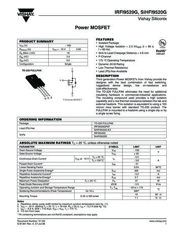
MOSFETSCONTENTHigh Current Power MOSFETwith Current Mirror andTemperature Sense DiodesUsing current mirror for current sensing in high current MOSFET applicationssignificantly reduces power loss in current sensing circuit and lowers design cost byreplacing expensive high power current sensors with inexpensive standard resistors.Two temperature-sensing diodes monolithically integrated in the MOSFET’s diemonitor the junction temperature of the MOSFET, rather than that of the package or heatsink temperature. This significantly increases the precision of temperature measurementand reduces the protection gap for operating ambient temperature with minimal risk ofdamaging the device.By Anatoliy Tsyrganovich, Leonid Neyman, and Abdus Sattar, IXYS CorporationIXYS MMIXT132N50P3 contains the current mirror to monitor thedrain current in a major device and two diodes with common cathodeutilizing the same die as the major device for temperature monitoring.The MMIXT132N50P3 symbol is shown in Figure 1 [1].As shown in Figure 2, MMIXT132N50P3 contains an N 1 identicalstructure with which N structures create the major MOSFET and the(N 1)th structure creates the current mirror. For this particular design,N 200, and if no current sense resistor in the current mirror’s sourceis used (RCS 0), the current mirror’s current is exactly 1/200 of themajor device source current. There is no dependency on the MOSFET’s drain/source voltage VDS, and, as a result it is temperatureindependent, providing measurements with maximum precision. However, if some sensor with finite resistance is used to convert currentinto voltage, the result of the measurement becomes VDS-dependentbecause of the resistive divider created by the MOSFET’s channelresistance RCH and current sense resistor RCS. This is especiallyimportant at low IDS when drain/source voltage is low as well.Figure 1: MMIX1T132N50P3 Device SymbolThe current mirror is created as a part of the major MOSFET structurewith common drain (D) and gate (G) terminals and separated sourceterminals (S and CS). To minimize errors related to the voltage dropon bounding wires from the source current of the major device, twoseparate terminals, one for a current mirror current return (SR) andthe other for gate charge/discharge current (GR), are provided inthe device. Temperature sensing diodes have separate terminals foranodes (A1, A2) and common cathode terminal (CC).Current Mirror DescriptionThe schematic diagram for the MMIXT132N50P3 current mirror isshown in Figure 2.Figure 2: Current MirrorSchematic Diagram38Bodo s Power Systems Figure 3: VDS vs. IDSLegend: Solid line - MOSFET is in ON state and channel is connectedin parallel to the body diode Dashed line – MOSFET is in off state andbody diode is conducting onlyMay 2016www.bodospower.com
MOSFETSCONTENTFigure 3 shows the MMIXT132N50P3 drain/source voltage drop(VDS) as a function of the drain/source current (IDS) at currents below10 A, with currents flowing in both directions when drain is positivewith respect to source (normal operations) and drain is negative withrespect to source (inverse connection) with the MOSFET in ON andOFF states. If the MOSFET is in ON state, VDS is described asVDS RDS(on) * IDS irrespective of IDS polarity. If MOSFET is in OFFstate and the body diode only sources current, VDS is determined bythe voltage drop across the body diode. Figure 4 shows a voltagedrop across the current sense resistor (VCS) and Figure 5 representsthe current through the current sense resistor at the same conditionsas in Figure 3.If full VDS voltage is applied to the current mirror, its current hasmaximum value, which is equal to IDS/200. Decreasing this voltage to54% of the VDS due to high RCS decreases ICS to 40% of its expectedvalue.Figure 6: Utilizing Current Mirror’s Current ICS vs. Current Mirror’sHead Room (VDS – VCS) at IDS 10 ATherefore, a compromise between precision of measurement andsignal level is required. High precision of the current measurementrequires low value current sense resistors and signal amplifying, whilelow precision measurement may utilize high value current senseresistors at the expense of temperature dependency.Figure 4: VCS vs. IDSFigure 7: Utilizing Current Mirror’s Current ICS vs. Current Mirror’sHead Room (VDS – VCS) at IDS -10 AFigure 5: ICS vs. IDSFigures 4 and 5 clearly demonstrate that increasing current sense resistance RCS increases VCS but decreases ICS. With RCS 0.5 ohm,ICS is close to the expected current mirror current, but VCS is low. Forexample, at IDS 10 A, expected ICS 10/200 0.05 A, while actualICS 46 mA, while with RCS 200 ohm, VCS is close to VDS (320 mVvs. 440 mV), but IDS is only 1.57 mA, i.e. only 3.1% of the expectedcurrent. Figure 6 shows that it is a linear function between the currentmirror’s “head room”, i.e. difference in voltage between VDS and avoltage drop across the current sense resistor (VCS) and maximumIDS current that can be provided by the current mirror.40Bodo s Power Systems Figure 8: ICM vs. Negative IDS with MOSFET in ON and OFF StatesCurrent Mirror Behavior with Body Diode ActiveFigure 3 shows that when the MOSFET is in ON state and negativevoltage is applied to the drain with respect to source, the channelMay 2016www.bodospower.com
MOSFETSCONTENTintercepts the entire current as long as the voltage drop across thechannel is less than the body diode forward voltage and current is notflowing through the diode. In this case, the current mirror’s behavior isthe same as with positive current (see Figures 4 and 5).However, if the MOSFET is in OFF state and negative voltage is applied to the drain with respect to source, the current mirror’s behaviorvaries significantly from the expected behavior.At first, the proportion between currents through the current mirror’sbody diode and major body diode is not equal to 1/200 as expected;instead, it is 0.52/200, i.e. two times less. This can be due to the current mirror’s body diode utilizing significantly less silicon volume thanthat of the major body diode, resulting in higher resistance.interception point, two structures (body diode and conducting channel) working in parallel results in higher VDS voltage drop than if bodydiode is conducting only. At this region, body diode and MOSFET’schannel cannot be interpreted as two independent structures likediode and resistor connected in parallel. It means that to get higherefficiency, MOSFET should be turned off after absolute value of thenegative current goes above interception point.Also, current mirror behavior in this region becomes very complex.Figure 10 shows the current mirror’s current ICM as function of thedrain/source current IDS with RCS 0.5 Ω, and figure 11 shows utilization of the current mirror’s current normalized to expected value of1/200 of IDS.Further, as shown in Figure 7, ICM dependency from the currentmirror’s head room is not linear any longer, and without regard to relatively high head room voltage, current falls dramatically. Therefore, inthis case, the current mirror’s output primarily copies VDS, determinedby a major body diode’s voltage drop. Even the highest head roomvoltage on the current mirror does not guarantee linearity betweenIDS and ICS currents, as shown in Figure 8.Because of such behavior, the current mirror is not recommendedfor precise current measurements at negative IDS currents, if thebody diode is conducting. However, the signal from the current mirror can be used to trigger the gate driver to activate the MOSFETand connect the channel in parallel to the body diode. It significantlydecreases the voltage drop on the MOSFET and improves efficiencyat currents creating lower voltage drop on the channel than the bodydiode conducting voltage.Current Mirror Behavior at High Negative CurrentsFigure 9 shows the MMIXT132N50P3 drain/source voltage drop(VDS) as a function of the drain/source current (IDS) at currents upto -40 A, with currents flowing when drain is negative with respect tosource (inverse connection) with the MOSFET in ON and OFF states.Figure 10: ICM vs. Negative IDS with MOSFET in ON and OFF StatesICM current lost linearity immediately after interception point atIDS -17 A. Utilization of the ICM raises up to 1 immediately after thatpoint and falls fast after that to the level determined mostly by a bodydiode. Using current mirror’s current at IDS 17 A for regulation orcurrent monitoring purposes becomes problematic due negative current mirror’s resistance, which may results in oscillations.Figure 11: Utilizing Current Mirror’s Current ICS vs. Negative IDSFigure 9: VDS vs. IDS at high negative currentsLegend: Red line - MOSFET is in ON state and channel is connectedin parallel to the body diodeBlue line – MOSFET is in off state and body diode is conducting onlyIf the MOSFET is in ON state, RDS(on) becomes function of IDS at highnegative currents. When absolute value of the drain/source voltagedrop VDS raises above 0.6 V, body diode starts conducting, whichresults in increased RDS(on) value. As a result, interception of twocurves appears earlier than we may expect based on steady RDS(on)value at low currents, i.e. at -17 A instead of -20 A. Moreover, afterwww.bodospower.com Current Mirror Application SchematicFigure 12 depicts a typical application circuit for positive currentmeasurement. It contains operational amplifier U1 with gain 10 thatallows converting of a 40 A drain/source current into a 2 V ADC inputsignal.It is recommended that the A to D conversion be started with a 600ns delay time after the Q1 gate is activated to avoid errors relatedto gate charge current flowing through current sense resistor R1.Additionally, close attention should be paid to the PCB layout to avoidhigh source current flowing through signal ground traces. Signal andpower ground traces should be kept connected at one point only atthe source current output.May 2016Bodo s Power Systems 41
MOSFETSCONTENTFigure 13 represents an application with acircuit that monitors cycle-by-cycle overcurrent conditions and turns the MOSFEToff immediately upon occurrence of suchconditions. It includes comparator U1 witha 64 mV threshold and 36 mV hysteresis,which has logic high output if voltage drop atcurrent sense resistor does not exceed 100mV. This circuit also includes trigger U3, gatedriver U5, input buffer with Schmitt triggerU9, blanking time generator U6, U7, U8, andauxiliary logic U2, U4.The device starts with a signal applied tothe IN input, which sets the gate driver’s U5output high turning MOSFET Q1 on. Bothchannels of the driver U5 are used in parallelto increase the driver’s current capability.Schmitt trigger U9 is used to improve inputsignal noise immunity.Figure 12: Positive Current Mirror Current Measurement CircuitIf the drain/source current exceeds the comparator’s threshold, which corresponds to Ids 14.8 A, the comparator trips into logic lowstate that resets trigger U3 and aborts the input pulse which kept the MOSFET’s Q1 gatehigh. When current falls below the comparator’s threshold and the comparator’s outputbecomes logic high again, trigger U3 outputremains low until the next pulse is applied tothe IN terminal.Logic elements U6, U7, and U8 with theR8C3 network create a blanking time generator that keeps the comparator’s outputlogic high for 600 ns to finalize the transitionprocess related to gate charge.The drain/source current value at whichcurrent is interrupted can be adjusted by thecurrent sense resistor value or comparator’sthreshold value, or both.Figure 13: Positive Current Cycle-by-Cycle Overcurrent Monitoring SystemFigure 14 represents an application with acircuit that monitors negative current flowingthrough the MOSFET’s body diode. It turnsthe MOSFET ON if the current exceeds thepreset threshold, and switches it OFF, whenit falls below this value. It includes comparator U1 with a 47 mV threshold and 34 mVhysteresis, which has logic low output if theabsolute value of the voltage drop at currentsense resistor does not exceed 80 mV. Thiscircuit also includes trigger U5, gate driverU10, input buffer with Schmitt trigger U11,blanking time generator U7, U8, U9, andauxiliary logic U2, U3, U4, and U6.If a signal is applied to the IN terminal, thedevice operates as a standard gate driverregardless of the direction of the drain/sourcecurrent setting gate driver’s U10 output highand MOSFET Q1 ON state. Both channelsof U10 are used in parallel to increase the42Bodo s Power Systems Figure 14: Negative Current (Body Diode Current) Monitoring SystemMay 2016www.bodospower.com
CONTENTdriver’s current capability. Schmitt triggerU11 is used to improve input signal noiseimmunity.currents. One possible solution is to separatecurrent sense resistors with low forward voltage diode, as shown in Figure 15.ositive Current Cycle-by-Cycle Overcurrent Monitoring System Current sense resistors R1 and R4 areHowever, if no external signal is applied toby diodeD1. For a negative curthe atINwhichterminaland theMOSFET’scanbodye current valuecurrentis interruptedbe adjustedseparatedby the currentsenser comparator’sthresholdor both.rent, only resistor R4 is used and its valuediodecurrentvalue,exceedsthe comparator’s U1epresents anthreshold,applicationa circuitnegative currentflowingtheto negative utgoes thatlogicmonitorshigh, actiy diode. It turns the MOSFET ON if the current exceeds the preset threshold, andFor a positive current, both resistors are convates the gate driver, and turns the MOSFET, when it falls below this value. It includes comparator U1 with a 47 mV threshold and 34parallelwith diode D1 in series withto ONconnectingthe MOSFET’schanwhich has logiclowstate,outputif the absolutevalue of thevoltage necteddrop at incurrentsenseresistorR1.Thisbuffercreatesnelin parallelto thebodydiode triggerand reducingot exceed 80mV.This circuitalsoincludesU5, gate driverU10,inputwithsome nonlinearityU11, blankingtimegenerator voltageU7, U8, dropU9, andauxiliary logic U2,U3, positiveU4, andcurrents;U6.at lowhowever, it does notthedrain/sourceto increaseplied to the INterminal, the device operates as a standard gateaffectdrivertheregardlessof thearea wherepositive current shouldefficiency.drain/source current setting gate driver’s U10 output high and MOSFET Q1 ON state.of U10 are used in parallel to increase the driver’s current capability. Schmitt trigger U11 ise input signal noise immunity.external signal is applied to the IN terminal and the MOSFET’s body diode currentmparator’s U1 threshold, its output goes logic high, activates the gate driver, and turns theN state, connecting the MOSFET’s channel in parallel to the body diode and reducing theltage drop to increase efficiency.current falls below the comparator’s U1 threshold, its output goes logic low, which turnsand the MOSFET OFF. After that, low negative current flows only through the body diodews for automatic turn on/off of the MOSFET in case it operates as a diode in motor driveconverters without engaging special controllers to synchronize the input signal of the gateal diode current.r’s threshold in this schematic corresponds to Ids –0.8 A to turn the MOSFET on and he MOSFET off. The threshold can be adjusted to another current value by changingesistor R1 or the comparator’s initial setting.Better safethan sorry!DC/DC Convertersfor IGBT & SiCUp to 6.4kVDC isolationNegative Current (Body Diode Current) Monitoring System wU7, U8, and U9 with the R8C3 network create a blanking time generator that keeps theutput logic level unchanged for 600 ns to finalize the transition process related to gateAsymmetric outputsge.forIGBT & SiCtive and negative current comparators in the same design requires different current sensevide desired lesolutionistoFigure 15: Separating Current Sense Resistors with Diodent sense resistors with low forward voltage diode, as shown in Figure 115.Reinforced isolationesistors R1 andR4negativeare separateddiodeD1.theFor a negativebecurrent,resistorR4 islimited.onlyFigure16 representsa voltageWhencurrentbyfallsbelowue determines the sensitivity to negative current. For a positive current, both resistors aredropnonlinearityat current sensecomparator’sU1 withthreshold,output1W & 2W DC/DC convertersarallel with diodeD1 in seriesresistoritsR1.Thisgoescreates someat low resistor R1 vs. drain/sourcebecurrentwith 49.9 ohm andgatewheredriverpositiveU10 andcurrent shoulds; however, itlogicdoeslow,notwhichaffectturnsthe arealimited. R4FigureR1 10ohmR1 ohm 4.99 ohm.theatMOSFETOFF. Afterthat,a voltage dropcurrent senseresistorR1lowvs.negativedrain/source currentwithR4 and 49.9UL / IEC / EN 62368-1 &m and R1 current4.99 ohm.flows only through the body diodeUL / IEC / EN 60950 certifiedTemperature Measurement Diodesagain. This allows for automatic turn on/off ofSeparating Current Sense Resistors with Diode Use diodes as temperature sensors basedthe MOSFET in case it operates as a diodeon the relatively high temperature coefficientinmotordrivecircuitsorbuckconvertersYEA RVoltage Drop at Current Sense Resistor vs. Drain/Source Currentof about 0.2 mV/ C, which is fairly linear.withoutengagingspecialarating CurrentSenseResistors controllers to synchronize the input signal of the gate driverarMeasurementwithDiodesThe current flowing through the diode when itactual diode current.rantyemperature sensors based on the relatively high temperature coefficient of about 0.2is forward biased is equal to [2]s fairly linear.VThe comparator’s threshold in this schematic,ηVT 1), where I iswing through correspondsthe diode whenit is forwardbiasedis equalSto Ids–0.8 A toturn theMOS-to [2] I Is (euration current, V is the diode’s forward voltage drop, η is ideality factor (a constant whichFET on and –0.4 A to turn the MOSFETwhere IS is the reverse saturation current,ging from 1 to 2), VT kT/q is the thermal voltage of the diode, T is the absolute junctionoff. The -19thresholdbe adjustedanotherV -23is theforward voltage drop, η isKelvin, q 1.602*10C is thecanelectroncharge,toandk 1.38*10J/Kdiode’sis the Boltzmann’scurrent value by changing current senseideality factor (a constant which has a valueresistor R1 or the comparator’s initial setting.ranging from 1 to 2), VT kT/q is the thermalvoltage of the diode, T is the absoluteLogic elements U7, U8, and U9 with thejunction temperature in Kelvin,R8C3 network create a blanking time genq 1.602*10-19 C is the electron charge, anderator that keeps the comparator’s outputk 1.38*10-23 J/K is the Boltzmann’slogic level unchanged for 600 ns to finalizeconstant:the transition process related to gate charge/discharge.If a known current is flowing through thediode, its temperature can be determined asIfflowinga knowncurrentflowingitsvoltagetemperaturebe determineda ecan bedetermineda functionof the as a function of theUsingIf bothpositiveandisnegativecurrenta functionof the diode,forwarddrop sumingthat:ηVηVvoltagedrop asthat e T 1:forward voltage dropforwardas followsassumingthatfollowse T assuming1:different current sense resistors to provideqIqIT V /ln ( )T V /ln ( )desired thresholds for positive and negativekηISkηISThisthereversesaturationI S andidealityfactor η, which are part-dependentThis equation containstheequationreverse containssaturationcurrentI S andidealitycurrentfactor η,whichare part-dependentand shoulddetermined before measurement.and should be determinedbeforebemeasurement.www.bodospower.com May2016Bodo s Power Systems 43knownI1 and I2 thearediode,passedthe diode,or aretwo usedidentical diodes are usedIf two known currentsIf ItwoI2 arecurrentspassed throughorthroughtwo identicaldiodes1 andqI2qI2(V)simultaneously,its determinedtemperatureascanbe(Vdetermined/ ln ( from) , withsimultaneously, its temperaturecan beT / asln (T ) , withthe IS excluded from theS 1excluded2 IV2 V1 )3WE POWER YOUR PRODUCTSwww.recom-power.comqkη I1If I2/Isimplifiessimplifiesequation. If I2/I1 10,equation.this equationtoequationT (V2 V1 ).to T (V2 V1 )1 10, thisq.kη I1
MOSFETSCONTENTThis equation contains the reverse saturation current IS and idealityfactor η, which are part-dependent and should be determined beforemeasurement.converters and used to calculate the die temperature of the MMIXT132N50P3. IXYS recommends the use of the microcontroller unit’sport as a 3.3 V voltage source to activate the circuit during temperature measurement only. Doing so helps prevent self-heating of thediodes, which can be a source of errors in temperature measurement.References1. MMIXT132N50P3 Data Sheet; IXYS Corporation. 20162. Andrei Grebennikov (2011). “§2.1.1: Diodes: Operational principle”.RF and Microwave Transmitter Design. J Wiley & Sons. p. 59.ISBN 0-470-52099-X.www.ixys.comFigure 16: Voltage Drop at Current SenseResistor vs. Drain/Source Current with Didiode, its temperaturecan beCurrentdeterminedasResistorsa function of theode SeparatingSenseVthat eηVT 1:qIh thetemperaturecan beI1determineda function of theT diode, V Ifits/ln ( known)twocurrentsand I2 are aspassedkη V ISthroughthediode,ortwoidenticaldiodesareηVTtion currentfactor η, which are part-dependentsumingthat eI S and ideality1:Iusedqsimultaneously,its temperature can beement.T V /ln ( )d through thedetermineddiode,kη or twoISas identical diodes are usedqIsaturationascurrentη, whichare part-dependent) / lnfactoreterminedT (VI S2 and V1ideality( 2) ,, withIS excludedfrom thekη I1measurement.qies to Tthrough (VwithVI1 )excluded.2 thefromidenticalthe equation.passeddiodes are used2.3kη or twoS diode,qI2If I2can/Ias10,thisequationsimplifiestoIS excluded from thethatfortemperature(V)nicalbe diodesdetermined used V/ln(), measurement,with1 Tbe21 kη I1eme. The recommended forwardcurrentsare 1 mA for a singleqto T (V2 withV1 ) short. pulsesasimplifiesdifferentialschemeevery 1–3 seconds.2.3kη .to avoidself-heatingof thediodes,which maymeasurement,createondedidenticaldiodesthat can beusedfor temperatureial scheme. Theforwardcurrentsare 1 mA for a singleThe recommendedMMIXT132N50P3containstwo identicalµA for a differentialshortforpulsesevery 1–3 seconds.diodes schemethat can withbe usedtemperatureeommendedMeasurementto avoid self-heating of the diodes, which may createmeasurement,eitherinasingle-endedordiagram which is recommended for temperature measurementdifferentialscheme.The recommendedodes. It containstwo currentsourcesgenerating stable currents.eratesmA forwardcurrent, currentswhile thearesecondsource (U1:B,1 mAcurrentfor a singleerature1 MeasurementresistorR5 providestheabilityfromfirstematicdiagramwhichis hemeandto1 adjustmA and100µAfor atheoportion.Voltagedrop acrossdiodessourcesis measuredby ADCated diodes.It containstwo currentgeneratingdifferentialschemewith short pulsesevery stable currents.emperatureIXYS recommendsthe(U1:B,1)generatesof1 themA MMIXT132N50P3.current, while the secondcurrent source1–3seconds.Higher,currentsare not3.3 V voltagesourceto sistorR5providesthe abilityto adjustcurrentfrom the firstrecommendedavoidcanself-heatingof thentofthe diodes,whichbe aissourceof ossdiodesmeasuredby ADCdiodes,ofwhichmay create incorrectresults.e die temperaturethe MMIXT132N50P3.IXYSrecommends thert as a 3.3 V voltage source to activate the circuit during temperaturematicfor TemperatureMeasurementwith Two of errors inpreventself-heatingofthediodes, whichcan Diodesbe a sourceApplicationSchematicfor TemperatureMeasurementFigure17 showsMeasurementa typical rewith TwoDiodes es: Operationalprinciple".RF and MicrowaveTransmitterwhichis recommendedfor temperature0-52099-X. measurement using two MMIXT132N50P3S Corporation.2016 diodes. It contains two currentintegrated1: Diodes: Operational principle". RF and Microwave Transmittersources generating stable currents. The firstN 0-470-52099-X.current source (U1:A, U2:1) generates 1 mAcurrent, while the second current source(U1:B, U2:2) generates 100 µA current.Variable resistor R5 provides the ability toadjust current from the first current sourceto obtain an exact 1:10 proportion. Voltagedrop across diodes is measured by ADCFigure 17: Typical Application Schematic for Temperature Measurement with Two Diodes44Bodo s Power Systems May 2016www.bodospower.com
mirror's "head room", i.e. difference in voltage between V DS and a voltage drop across the current sense resistor (V CS) and maximum I DS current that can be provided by the current mirror. If full V DS voltage is applied to the current mirror, its current has maximum value, which is equal to I DS/200. Decreasing this voltage to 54% of the V