Transcription
Generic Control Allocation Toolbox for PreliminaryVehicle DesignJing Pei NASA Langley Research Center, Hampton, Virginia, 23681George Z. Bassett†University of Texas at Austin, Austin, Texas, 78712James Grisham‡University of Texas at Arlington, Arlington, Texas, 76019Peter Finch§Stanford University, Stanford, CA, 94305Matthew Toniolo¶Analyical Mechanics Associates, Hampton, Virginia, 23681Luke Miller kand Bandu Pamadi NASA Langley Research Center, Hampton, Virginia, 23681This paper describes the development and application of a Generic Control AllocationToolbox developed at NASA Langley Research Center (LGCAT) intended to aid engineersduring the preliminary design phase of an aerospace vehicle. The static controllability spacein the forms of a Theoretical Attainable Moment Set, Φ, or Theoretical Attainable ForceSet, φ is difficult to visualize for modern vehicles with multiple types of redundant controleffectors. The objective of LGCAT is to provide system engineers and designers early inthe vehicle design phase with quick insights on how control effector parameters such asquantity, sizing, location, orientation, redundancy, etc., affect the overall controllabilityand other performance metrics. Having such information in hand allows system engineersto make more informed decisions on overall mission objectives such as performance vs.reliability vs. cost, etc. early in a vehicle design phase and reduce the number of iterationsnecessary in the design and analysis cycles. LGCAT can accept a variety of control effectortypes including aerodynamic surfaces, rotors, thrust vector control (TVC) engines, andreaction control systems (RCS). LGCAT is MATLAB based, user friendly, and is capableof performing the analysis in the Graphical User Interface (GUI) or script mode. Currentadd-on features include interfacing with engineering level codes such as Vehicle Sketch Pad(VSP) and generating the corresponding Φ and φ for an arbitrary vehicle design. Thesecapabilities potentially make LGCAT an integral part of the preliminary design phase forany vehicle. AerospaceEngineer, Vehicle Analysis BranchGraduate Student, Georgia Institute of Technology‡ PhD Student, University of Texas at Arlington§ Graduate Student, Stanford University¶ Aerospace Engineer, Analytical Mechanics Associatesk Pathway Student, Flight Dynamics Branch Retired Aerospace Engineer, Vehicle Analysis Branch† Currently:1 of 17American Institute of Aeronautics and Astronautics
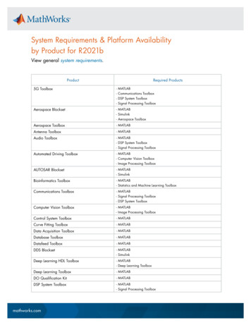
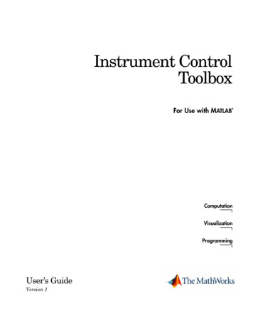
I.IntroductionTypical modern aerospace vehicles, ranging from aircraft to launch vehicles to spacecraft, have multipleredundant control effectors to meet performance and fault tolerance requirements. Figure 1 shows severalwell-known examples across the spectrum of aerospace vehicles: GL-10, SLS, MLAS, Space Shuttle, F-16,and Cassini Spacecraft. Depending on the vehicle flight regime (endo-atmosphere, exo-atmosphere, or both)and mission requirements, the typical control effector options are: aerodynamic surfaces, propellers, thrustvector control (TVC), reaction control system (RCS), reaction wheels (RW), control moment gyros (CMG),and torque rods. The vehicle controllability space can be viewed in the forms of: Theoretical AttainableMoment Set, Φ1–3 or Theoretical Attainable Force Set, φ. As a vehicle design becomes more complicatedwith a mixture of effector types, such as with the GL-10, it is virtually impossible for the analyst to visualizeΦ or φ without the aid of a numerical toolbox.Figure 1: Examples: Aerospace Vehicles with Redundant EffectorsThe control allocation problem addresses how control effectors of a vehicle should be positioned in orderto achieve a certain command (usually three-axis moment or force) from the output of some control law. Itis typically defined as:3 given a column matrix of desired moments, mdes , control effectiveness matrix, B,lower and upper limits of each effector (umin and umax ), find u that satisfies:Bu mdess.t.umin u umax(1)The number of control effectors is generally greater than the dimension of the desired force or moment andit is usually up to the Guidance Navigation & Control (GN&C) team to develop the “best” algorithm thatminimizes some objective function1–5 (e.g., error between the commanded and actual moments in additionto the total effector usage) while satisfying certain constraints (e.g., servo maximum position and rate limitsor RCS thruster minimum and maximum on-time). This level of analysis is often performed much later inthe vehicle design phase.The importance of analyzing static control allocation metrics such as Φ or φ, early in a vehicle designphase is often overlooked. It is crucial for the system designers to have insights into how parameters such ascontrol effector effectiveness, quantity, location, size, and orientation influence the overall admissible controlspace. Having such knowledge allows the engineer to make informed decisions about crucial matters suchas: 1) the minimal suite of control effectors required to still meet the desired system performance metrics, 2)the extent of sufficiency in three-axis control in the event of an effector failure, 3) ratio of control authoritycompared to the disturbance moment set (e.g., the Space Shuttle heritage criteria for the RCS system requiresthe control torque to exceed all known disturbance torque by a factor of two), 4) optimal location for a set2 of 17American Institute of Aeronautics and Astronautics
of RCS thrusters given a set of constraints. Quick assessments of these types of issues early in the vehicleconcept development phase can mitigate schedule delays and reduce life-cycle costs.The motivation for the development of the NASA Langley Generic Control Allocation Toolkit (LGCAT),was to provide a general framework that incorporates key aspects of flight controls early in a vehicle designphase. The easy-to-use tool allows the analyst to perform quick trade studies and rapidly evaluate variouseffector configurations by comparing the corresponding Φ or φ. The modularity of LGCAT allows for amixture of control effector types and gives the analyst the options to either supply the parameters associated with individual effectors or enter a pre-computed control effectiveness matrix, B. Generalized inversesolutions to the control allocation problem are the most commonly used approaches due to their linearityand low computational cost.2, 3 With that in mind, there is a built-in pseudo inverse option that allows theanalyst to compare the particular attainable moment set,3, 6 Φ* to Φ. To the best of authors’ knowledge,Glaze and Durham first developed a similar MATLAB-based Control Allocation Toolbox6 (CAT). CAT isGUI driven and allows the user to input a pre-computed control effectiveness matrix and compare Φ* frompseudo-inverse or direct allocation schemes with Φ. However, the control effectiveness matrix is not alwaysknown especially for a configuration with a mixture of control effector types, e.g. TVC with aero surfaces.LGCAT works around this issue by giving the analyst the option to enter the control effector parameters,assemble the control effectiveness matrix internally, and subsequently compute Φ or φ.There is other related control allocation open-source software such as the MATLAB-based QuadraticProgramming Control Allocation Toolbox7 (QCAT). QCAT focuses on various control allocation methodsincluding: sequential least squares, weighted least squares, minimal least squares, interior point, cascadinggeneralized inverses, fixed-point iterations, direct allocation, and dynamic allocation. Similar to CAT, QCATis only capable of modeling effectors which are described in terms of control effectiveness matrix. QCATis geared towards design of a specific control allocation scheme which serves an excellent complimentarytool to LGCAT. The rest of the paper is organized as follows: Section II provides an overview of theLGCAT framework including: underlying assumptions, available control effector types, inputs, and thepossible analysis outputs. Section III compares results from LGCAT to those published in open literature.Section IV highlights several examples in which LGCAT can be beneficial in vehicle preliminary design.II.LGCAT DescriptionThe overall framework of LGCAT is presented in this section. Thus far, the program allows the analystto examine a vehicle configuration with any combination of four control effector types (classes): aero surface,reaction control system (RCS), aircraft propeller (rotor), and thrust vector control (TVC). It is assumed thateach effector produces a local force, and by virtual of being positioned at some distance away from the centerof mass, a moment can be produced. In certain applications, the quantities of interest could be impulse orangular impulse. Given an expression which relates an effector input (x) to a force, F(x), moment M(x),impulse J(x), and angular impulse L(x) are computed as follows:M(x) r F(x)Z tfJ(x) F(x) dt0Z tfL(x) M(x) dt(2)(3)(4)0where r is a position vector which represents the location of the control effector relative to the center ofmass. Evaluating these quantities over the set of all admissible control deflections, Ω and obtaining theconvex hull,3 quantities such as the theoretical attainable moment set, Φ, theoretical attainable force set,φ, theoretical attainable angular impulse set, Φ’, and theoretical attainable impulse set, φ’ can be readilyobtained.3 of 17American Institute of Aeronautics and Astronautics
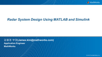
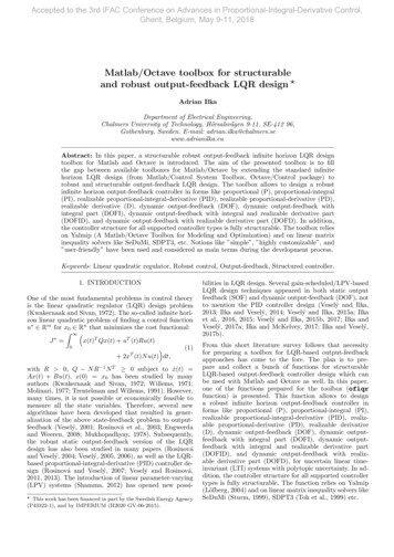
Figure 2: LGCAT GUI Main WindowFigure 2 is a snapshot of the main analysis window. The “desired output” dropdown option allows theuser to select the desired analysis output: Φ, φ, Φ’, or φ’. The “control effector manipulation” buttons yielda popup screen that allows the user to edit the effector parameters such as displacement limits, effectivenessand locations. The visualization screen allows the user to visualize the locations and types of control effectors(color-coded) with respect to the vehicle center of mass. Once the analyst is done entering all the effectors,pressing the “run” button yields the convex hull for any one of the desired outputs. Since the pseudo inversesolution is by far the most common solution to the control allocation problem, LGCAT has a built-in optionthat computes Φ* and φ* , and allows the analyst to visually compare the convex hull from the pseudoinverse solution with the theoretical maximum.A.AssumptionsIn order to develop a generic tool which is capable of handling several types of control effectors, certainsimplifying assumptions were made. Static controllability analysis. Only the position limits (umin and umax ) of the effectors are considered.LGCAT focuses primarily on obtaining the theoretical attainable moment or force sets Φ and φ. Howthe effectors may have arrived at those positions (rate limit, etc) is not considered. Force for a given control input is time invariant. Using this assumption, Eq. (3) and (4) becomeJ(x) F(x) tf(5)L(x) M(x) tf(6) Integrations for impulse and angular impulse are performed for a single second. In the case of vehiclesthat only contain RCS thrusters, integrations for impulse and angular impulse are integrated for eachRCS thruster’s max on-time. Thrust vector control (TVC) implementation assumes that the engine has two degrees-of-freedom(DOF) and can only pivot in the y-z plane.4 of 17American Institute of Aeronautics and Astronautics
B.Effector TypesA brief description of the the four types of effectors implemenented thus far in LGCAT is provided in thissection: aero surface, reaction control system, aircraft propeller (rotor), and thrust vector control.1.Aero surfacePure aerodynamic control effectors generally deflect some flap about a hinge line that generates a localaerodynamic force by modifying the flow over the surface. By virtue of being positioned at some distancefrom the center of mass, an aerodynamic moment can be generated. For moments (roll, pitch, yaw), thecontrol effectiveness matrix for m aero surfaces may be represented as M1 M1 M1. u2 um u1 M2 M2 M2 (7)B . u u2 um 1 M3 M3 M3. u1 u2 umGiven a column matrix of surface deflections, the net moment on the flight vehicle would be computed asfollows:M Bu(8)where u is a column matrix of inputs (deflections for aero surfaces) which can be written as {u1 , u2 , . . . , um } .Given this approach to modeling aero surfaces, a single aero surface can be represented by the correspondingcolumn in the control effectiveness matrix along with limits on the possible deflections. To obtain Φ, LGCATgives the analyst the option to either input the control derivatives in the form of a control effectiveness matrix, B, or specify the partials of force vs. deflection along with the position vector from the control surfaceto the center of mass.2.Reaction control systemReaction control systems (RCS) are modeled using a force vector and thruster on-time. The input to theRCS module is binary, either 0 for off or 1 for on. That is, the thruster either produces zero force or itproduces a force equivalent to f if it is on. Time becomes important when computing impulse and angularimpluse, which represent integrals of force over time and moment over time, respectively. Currently, theseintegrals are obtained over one second for the sake of simplicity. In cases where the RCS thrusters on-timelimit is less than one second, the following logic is used to compute J:if ton tfJ(x) F(x) ton(9)J(x) F(x) tf(10)otherwise ton tf :where tf is set to one second.3.Aircraft PropellerThe rotor parameters that are used to calculated force and moment are described below. T̂ – unit thrust vector. r – rotor position vector. CT – coefficient of thrust. CQ – coefficient of torque. Ω – motor angular velocity (radians per second).5 of 17American Institute of Aeronautics and Astronautics
Given these parameters, the force and moment generated can be calculated using Eq. (11) and (12),respectively. For m rotors, the input would be a column matrix of motor angular velocity commands, Ωm 1F CT Ω2 T̂hiM CT (r T̂) CQ T̂ Ω24.(11)(12)Thrust vector controlGeneric thrust vector control (TVC) parameters used to compute forces and moments are described below. ψ, engine deflection in pitch direction (rad) φ, engine deflection in yaw direction (rad) Fo , force vector for un-deflected engine r, position vector from the CM to engineGenerally, the engine has some undeflected force vector, Fo . It is located at some position vector awayfrom the CM, r, and has two degrees-of-freedom (DOF) which allowes to pivot (gimbal) about the y and zaxes of the vehicle. The engine is usually driven by a pair of linear actuators and its range of travel is limitedto be within a constraint boundary prescribed by an ellipse normal to the undeflected thrust direction. Theengine deflection limits in the pitch and yaw directions, ψ and φ describes the shape of the ellipse. Twosequential rotations about the z and y axes can be made to rotate the undeflected force vector to somedesired direction subjected to the elliptical constraint shown in Eq. 13 and 14. For a given pitch and yawcommand, if the value of Eq. 14 is greater than unity then the constraint has been violated. Hence, thecommand is considered inadmissible and the force does not contribute to the attainable set. If the value isless than or equal to 1 then the command is considered admissible and the resultant force vector contributesto the attainable set. These sets of conditionals can be seen in Eq. 15. cos(φ) 0 sin(φ)cos(ψ) sin(ψ) 0 Fcheck (13)010 sin(ψ) cos(ψ) 0 Fo sin(φ) 0 cos(φ)001ellipse N aN ,NaN N aNF cos(φ) 0 sin(φ)22Fcheck,zFcheck,y 2ψlimφ2lim(14)if ellipse 1 0 sin(φ) cos(ψ) sin(ψ) 0 10 sin(ψ) cos(ψ) 0 Fo , if ellipse 1 0 cos(φ)001(15)The resultant moment can be readily computed in Equation 16.M r FC.(16)Pseudo-Inverse Control Allocation MethodThe Moore-Penrose Pseudo-Inverse is a popular solution3 to the control allocation problem. It is generallypreferred due to its linearity and speed for real-time implementation. The pseudo-inverse allocation methodminimizes the sum of the squares of the control commands (uT u) subject to the constraint that Bu adwhere B is the control effectiveness matrix, ad is the given control command, and u is the control commands.36 of 17American Institute of Aeronautics and Astronautics
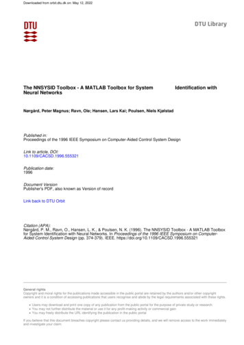
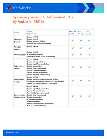
This is shown in Equation 17. The pseudo-inverse allocation algorithm however does not account for limitson the control effectors.u B T [BB T ] 1 ad(17)Due to the different mechanisms for which each type of effector produces a moment or force, the construction of a general B-matrix capable of handling various combinations of effectors proved to be mostchallenging. With the latest version of the software, it is capable of obtaining the pseudo inverse solution toΦ and φ for any combinations of aero surface, rotors, and TVC. The RCS class stands by itself in obtainingthe pseudo inverse solution for Φ’ and φ’ because of its discrete nature.III.Validation CasesA series of “check cases” was performed that compared the outputs of LGCAT with results published inthe literature. Comparisons are qualitative in terms of the shape of the attainable sets and quantitative interms of volumes of the attainable sets.A.Aero surfaceThe aero surface control effector was validated by reproducing the results from Glaze and Durham.6 Thisexample is based on a linear approximation of F-18 HARV aerodynamic data which was linearized about aflight condition of 10,000 ft, Mach 0.3, at a 12.5 angle-of-attack. The resulting control effectiveness matrixin terms of normalized rolling, pitching, and yawing moments can be seen below: 4.382 10 2 0.53301.100 10 2 4.382 10 2 0.5330 1.100 10 2 5.841 10 2 6.486 10 2 3.911 10 3 5.841 10 2 6.486 10 2 3.911 10 3 1.674 10 20.000 7.428 10 2 B 6.280 10 2 6.234 10 20.000 6.280 10 26.234 10 20.000 5 4 2.920 10 21.00 103.00 10 1.000 10 50.35531.000 10 5 1.000 10 21.000 10 50.1485The ten independent control effectors and their input limits are shown in Table 1. Using the abovecontrol effectiveness matrix and input limits for each effector, the theoretical attainable moment set (Φ) wascomputed using LGCAT and compared with Ref. 6. Figure 3 shows Φ obtained by LGCAT. The differencesin Φ and Φ* between Ref. 6 and LGCAT are within 1%.7 of 17American Institute of Aeronautics and Astronautics
Controlu1u2u3u4u5u6u7u8u9u10Control effectorMinimum input (rad)Maximum input .52360.78540.78540.52360.52360.5236right horizontal tailleft horizontal tailright aileronleft aileroncombined ruddersright trailing-edge flapleft trailing-edge flaproll thrust vectoring controlpitch thrust vectoring controlyaw thrust vectoring controlTable 1: F-18 Example,6 control effector position limitsFigure 3: F-18 Example6 LGCAT, Φ 0.0894 (rad/s2 )3B.Thrust vector controlThrust vector control effector results were validated using the example from Ref. 2. The example representsa reusable booster concept. The vehicle specifications and thrust vector control parameters are provided inTables 2 and 3. Figure 4 shows Φ obtained by LGCAT. The percent differences in Φ and Φ* between Ref. 2and LGCAT are within 1.5%.8 of 17American Institute of Aeronautics and Astronautics
ParameterValueMassRoll Moment of Inertia, IxxPitch Moment of Inertia, IyyYaw Moment of Inertia, IzzCenter of Mass Location (from nose)44650 lbm0.2158e5 105 slug - ft23.3031e5 105 slug - ft23.4301e5 105 slug - ft2hiT 30.6500 0 2.6400 ftTable 2: Flight vehicle parameters2ParameterValue 3.39 6 , circular45000 lbfhiT1 0 0Thrust Plane AngleEngine Gimbal LimitEngine 1 - 3 ThrustEngine 1 - 3 Thrust VectorEngine 1 Gimbal from Center of MassEngine 2 Gimbal from Center of MassEngine 3 Gimbal from Center of Massh 21.21iTfthiT 21.35 1.45 0.43 fthiT 21.35 1.45 0.43 ft0 2.93Table 3: Thrust vector control parameters22Figure 4: Reusable Booster Example2 LGCAT, Φ 2.9722 (rad/s )39 of 17American Institute of Aeronautics and Astronautics
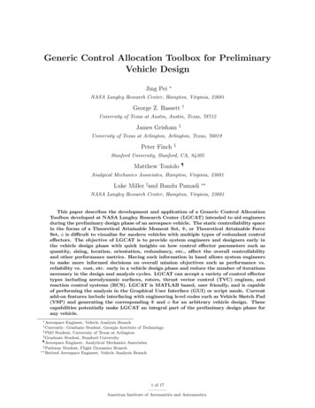
C.Reaction control systemReaction control system (RCS) results from LGCAT were validated using a 3U CubeSat configurationpresented in Ref. 8. The nominal RCS configuration is designed with the thrust vectors passing through theCubeSat CM (centroid of the middle U), in which case the system provides pure translational motion of theCubeSat without affecting rotational motion. It was assumed that the thrusters have a maximum on-timeof 0.2 seconds with a nominal force of 0.3 N. Figure 5 shows the 3U CubeSat configuration.Figure 5: CubeSat Example RCS Layout8Figure 6 shows the resultant theoretical attainable impulse set, φ, of the RCS configuration provided inRef. 8. Figure 7 shows φ computed by LGCAT. The difference between the results in the published paperwith those obtain with LGCAT is less than 0.01%.Figure 6: CubeSat RCS Example,8 φ 0.0016 Ns10 of 17American Institute of Aeronautics and Astronautics
Figure 7: CubeSat RCS Example8 LGCAT, φ 0.00158 NsIV.Application of LGCATThe primary function of LGCAT is to provide designers and analysts with a numerical toolbox thatallows easy visualization of the static controllability space in the forms of Φ or φ for complicated vehicleconfigurations with a mixture of control effector types. Having such information would allow the engineerto make informed decisions to crucial design questions such as: 1) the minimal suite of control effectorsnecessary while stil meeting the desired performance requirements, 2) sufficient control authority in theevent of a failed effector. This section highlights several applications of LGCAT in the vehicle design phaseincluding: 1) visualizing Φ for complicated vehicle configurations such the GL-10 and space shuttle, 2)serving as a complimentary tool to engineering level codes such as Vehicle Sketch Pad (VSP),9 AthenaVortex Lattice Method (AVL),10 and missile DATCOM,11 3) serving as an integral part of a framework foroptimizing effector design from a vehicle flight controls perspective.A.1.Using LGCAT to Visualize Complex Vehicle ConfigurationsGL-10GL-10 was designed at NASA Langley Research Center as an efficient hybrid-electric Vertical Take-Off andLanding (VTOL) aircraft.12 GL-10 is an extremely complicated configuration with multiple propellers andcontrol surfaces; in addition, the entire wing and tail can both be rotated. Hence, it is virtually impossibleto visualize the control moment space without the aid of a numerical tool. Figure 8 shows the three flightmodes of the GL-10 design.1211 of 17American Institute of Aeronautics and Astronautics
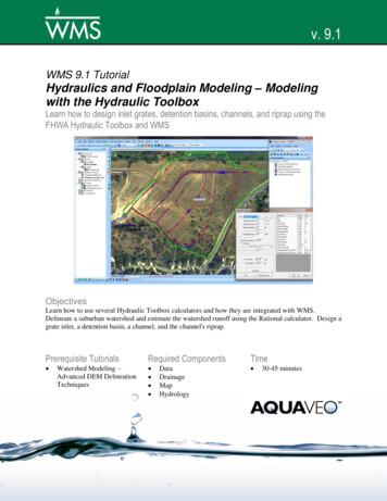
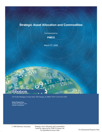
Figure 8: GL-10 modes of operation:12 hover, transition, and cruiseThe moment space for the hover mode is examined here. For hover, GL-10 uses all 8 rotors on thewing and the 2 rotors located on the tail to produce thrust in addition to the three moments. The vehicleand effector parameters including the admissible limits were entered into LGCAT and the tool output thetheoretical attainable moment set, Φ. Under nominal operations, the configuration has ample amount ofcontrol in all three axes shown by the blue volume in Fig. 9. The superimposed red volume represents thereduced moment space, Φ† (subset of Φ), in the event the far left rotor on the port side of the wing hasfailed. It is apparent that with the far left rotor out, the vehicle loses a significant amount of roll control.Furthermore, the shape of the moment space is no longer symmetric as expected.Figure 9: GL-10 Hover Mode, Φ nominal vs. and Φ† one rotor out12 of 17American Institute of Aeronautics and Astronautics
2.Space Shuttle’s Reaction Control SystemThe Space Shuttle’s Reaction Control System13 consisted of 38 primary RCS thrusters and 6 Vernier RCSthrusters that were used for attitude control during flight operations such as payload insertions and dockingwith the International Space Station (ISS). The layout of the 44 RCS thrusters is shown in Figure 10. TheRCS thrusters are split into two major sections: the forward and aft thrusters. The forward thrusters areused for on-orbit maneuvering while the aft thrusters are used for re-entry (along with the aero-surfaces).Figure 10: Layout of Space Shuttle’s Reaction Control System13Figure 11 shows the attainable moment set, Φ, for Space Shuttle’s RCS configuration. LGCAT allows thedesigner to quickly address important design questions such as the ratio of the control torque to disturbancetorques. One of the GN&C requirements was that the control torque must be at least a factor of two greaterthan all known disturbance torques (gravity gradient, solar radiation, atmospheric drag, etc.). With LGCAT,the analyst can co-plot the control moment set with the disturbance torque set and quickly address suchrequirements for such a complicated RCS configuration.13 of 17American Institute of Aeronautics and Astronautics
Figure 11: Φ for Space Shuttle’s Reaction Control SystemB.Using LGCAT with Vehicle Sketch PadVehicle Sketch Pad (VSP) is a popular parametric aircraft design tool.9 VSP allows the user to create rapidlya 3D model of an aircraft and contains built-in tools to conduct preliminary sizing, aerodynamic, and massproperty analysis. VSPAero is a vortex lattice solver and together with the VSP mass properties tool givesthe analyst a way of rapidly generating stability and control derivatives. Coupling VSP with LGCAT canallow aircraft designers to perform quick evaluation of the vehicle controllability metrics during explorationsof the configuration design space early in a design cycle. The process of creating an aircraft configurationand generating the stability derivatives in VSP, and then passing the results to LGCAT is demonstrated withan RV-7 configuration. The RV-7 has 4 control surfaces consisting of ailerons, rudder, elevator, and flaps.The control surface deflection limits are shown in Table 4. Figure 12 is a sketch of the RV-7 configurationgenerated in VSP.Controlu1u2u3u4Control effectoraileronrudderelevatorflapsMinimum input (rad)Maximum input ble 4: RV-7 Control effector position limits14 of 17American Institute of Aeronautics and Astronautics
Figure 12: RV-7 in VSPFigure 13 is an overlay of Φ at two flight conditions, α 0 (blue) and 2 (red). This is an excellentexample of how LGCAT can be used in conjunction with engineering level tools such as VSP,9 AVL,10and DATCOM11 in quickly assessing the vehicle controllability space at various operating conditions. Thisinformation in turn can affect design decisions such as operating flight envelope for aircraftsand UAVs orrequirements for system performance in the event of an effector failure.Figure 13: Φ RV-7 at AoA 0 and 2 15 of 17American Institute of Aeronautics and Astronautics
C.Using LGCAT to Optimize Effector Locations and OrientationsThis section describes how LGCAT can be used in a framework in which the designer can optimize thelocations and orientations of control effectors in a vehicle design to maximize some objective performanceparameter (i.e. Φ, φ) while meeting certain constraints. Figure 14 shows the schematic of such a framework.The general idea is to cast the effector design process into an optimization problem that can be readily solvedby software such as MATLAB’s fmincon function.14 This would ensure that an “optimal” solution has beenreached, whereas conventional design approaches are usually “ad-hoc”.Figure 14: Optimization FrameworkThe proposed Max Launch Abort System (MLAS) escape vehicle concept15 shown in Fig. 15 is anexcellent example of how the LGCAT optimization framework can be beneficial to vehicle design. The mainobjective of the MLAS is to get the crew capsule away from a failed launch vehicle as fast as possible duringtime of maximum dynamic pressure. The proposed design has six solid rocket escape motors positionedcircumferentially at 60 intervals. Each motor is canted outward 30 . Each escape motor is equipped withthrust vector control and nozzles can be deflected up to 15 in any direction outward of the fairing (nozzlesnot allow to deflect inward). To maximize axial acceleration one would minimize the cant angles as muchas possible. To maximize the control authority in the pitch and yaw axes one can either increase the cantangle or the gimbal angle capabilities. However, it is not intuitive what the optimum cant angles shouldbe if the design needs to achieve a certain axial acceleration profile and still be robust to uncertainties inthe aerodynamic disturbance torques. The LGCAT-based optimization framework described can be used toanswer such a design question. Furthermore in the event the design does not meet performance requirementsbecause of constraints on the cant angles, LGCAT can be used to answer questions such as additional gimbalangle range required (beyond the 15 limit) in order for the system to meet the specified requirements. Inthis example the optimal solution may appear to be trivial; however, for more complicated configurations,the optimization framework may be necessary to yield an “optimal” design.Figure 15: MLAS Escape Vehicle Concept1516 of 17American Institute of Aeronautics and Astronautics
V.ConclusionThe development and application of a Generic Control Allocation Toolbox developed at NASA LangleyResearch Center (LGCAT) is described in this paper. The objective of LGCAT is to provide system engineersand designers early in the vehicle design phase with quick insights on how control effector parameterssuch as quantity, sizing, location, orientation, redundancy, etc., affect the overall controllability and otherperformance metrics. Havi
Glaze and Durham rst developed a similar MATLAB-based Control Allocation Toolbox6 (CAT). CAT is GUI driven and allows the user to input a pre-computed control e ectiveness matrix and compare * from . reaction control system (RCS), aircraft propeller (rotor), and thrust vector control (TVC). It is assumed that