Transcription
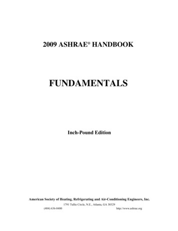
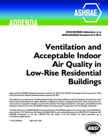
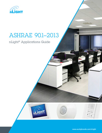
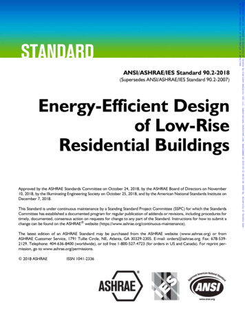
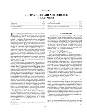
CHAPTER 62ULTRAVIOLET AIR AND SURFACETREATMENTFundamentals.Terminology .UVGI Air Treatment Systems.HVAC System SurfaceTreatment .62.162.362.562.9ULTRAVIOLET germicidal irradiation (UVGI) uses short-waveultraviolet (UVC) energy to inactivate viral, bacterial, andfungal organisms so they are unable to replicate and potentiallycause disease. UVC energy disrupts the deoxyribonucleic acid(DNA) of a wide range of microorganisms, rendering them harmless(Brickner et al. 2003; CIE 2003). Early work established that themost effective UV wavelength range for inactivation of microorganisms is between 220 and 280 nm, with peak effectiveness near 265nm. The standard source of UVC in commercial systems is low-pressure mercury vapor lamps, which emit mainly near-optimal 253.7nm UVC. Use of germicidal ultraviolet (UV) lamps and lamp systems to disinfect room air and air streams dates to about 1900 (Reed2010). Riley (1988) and Shechmeister (1991) wrote extensivereviews of UVC disinfection. Application of UVC is becomingincreasingly frequent as concerns about indoor air quality increase.UVC is now used as an engineering control to interrupt the transmission of pathogenic organisms, such as Mycobacterium tuberculosis(TB), influenza viruses, mold, and potential bioterrorism agents(Brickner et al. 2003; CDC 2002, 2005; GSA 2010; McDeVitt et al.2008; Rudnick et al. 2009).UVC lamp devices and systems are placed in air-handling systems and in room settings for the purpose of air and surface disinfection (Figure 1). Control of bioaerosols using UVC can improveindoor air quality (IAQ) and thus enhance occupant health, comfort,and productivity (ASHRAE 2009; Menzies et al. 2003). Detailed descriptions of UVGI components and systems are given in Chapter 17of the 2016 ASHRAE Handbook—HVAC Systems and Equipment.Upper-air (also commonly called upper-room) devices are installedin occupied spaces to control bioaerosols (e.g., suspended viruses,bacteria, fungi contained in droplet nuclei) in the space. In-duct systems are installed in air-handling units to control bioaerosols in recirculated air that may be collected from many spaces, and to controlmicrobial growth on cooling coils and other surfaces. Keeping thecoils free of biofilm buildup can help reduce pressure drop across thecoils and improve heat exchanger efficiency (therefore lowering theenergy required to move and condition the air), and eliminates onepotential air contamination source that could degrade indoor airquality. UVC is typically combined with conventional air qualitycontrol methods, including dilution ventilation and particulate filtration, to optimize cost and energy use (Ko et al. 2001).This chapter discusses these common approaches to the application of UVC products. It also surveys the most recent UVC designguidelines, standards, and practices and discusses energy use andeconomic considerations for the application of UVC systems. Photocatalytic oxidations (PCOs), another UV-based HVAC application, are not discussed in this chapter, but are addressed in Chapter47 of this volume.The preparation of this chapter is assigned to TC 2.9, Ultraviolet Air andSurface Treatment.62.1Energy and Economic Considerations.Room Surface Treatment.Safety .Installation, Start-Up, and Commissioning .Maintenance t energy is electromagnetic radiation with a wavelengthshorter than that of visible light and longer than x-rays (Figure 2).The International Commission on Illumination (CIE 2003) definesthe UV portion of the electromagnetic spectrum as radiation havingwavelengths between 100 and 400 nm. The UV spectrum is furtherdivided into UVA (wavelengths of 400 to 315 nm), UVB (315 to280 nm), UVC (280 to 200 nm), and vacuum UV (VUV; 200 to100 nm) (IESNA 2000). The optimal wavelength for inactivatingmicroorganisms is 265 nm (Figure 3), and the germicidal effectdecreases rapidly if the wavelength is not optimal.UV Dose and Microbial ResponseThis section is based on Martin et al. (2008).UVGI inactivates microorganisms by damaging the structure ofnucleic acids and proteins at the molecular level, making them incapable of reproducing. The most important of these is DNA, which isresponsible for cell replication (Harm 1980). The nucleotide bases(pyrimidine derivatives thymine and cytosine, and purine derivativesguanine and adenine) absorb most of the UV energy responsible forcell inactivation (Diffey 1991; Setlow 1966). Absorbed UV photonscan damage DNA in a variety of ways, but the most significant damageevent is the creation of pyrimidine dimers, where two adjacent thymine or cytosine bases bond with each other, instead of across the double helix as usual (Diffey 1991). In general, the DNA molecule withpyrimidine dimers is unable to function properly, resulting in theorganism’s inability to replicate or even its death (Diffey 1991; Milleret al. 1999; Setlow 1997; Setlow and Setlow 1962). An organism thatcannot reproduce is no longer capable of causing disease.UVGI effectiveness depends primarily on the UV dose (DUV ,μJ/cm2) delivered to the microorganisms:DUV It(1)where I is the average irradiance in μW/cm2, and t is the exposuretime in seconds (note that 1 J 1 W/s). Although Equation (1)appears quite simple, its application can be complex (e.g., when calculating the dose received by a microorganism following a tortuouspath through a device with spatial variability in irradiance). The doseis generally interpreted as that occurring on a single pass through thedevice or system. Although the effect of repeated UV exposure onmicroorganisms entrained in recirculated air may be cumulative, thiseffect has not been quantified, and it is conservative to neglect it.The survival fraction S of a microbial population exposed to UVCenergy is an exponential function of dose:S e–kDUV(2)where k is a species-dependent inactivation rate constant, in cm2/μJ.The resulting single-pass inactivation rate η is the complement of S:η 1–S(3)
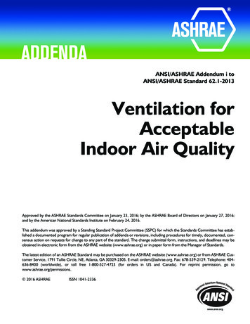
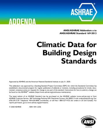
62.22019 ASHRAE Handbook—HVAC Applications (SI)Fig. 1 Potential Applications of UVC to Control Microorganisms in Air and on Surfaces(ASHRAE 2009)and is a commonly used indicator of overall UVC effectiveness, representing the percentage of the microbial population inactivatedafter one pass through the irradiance field(s).Inactivation rate constants (k-values) are species-dependent andrelate the susceptibility of a given microorganism population to UVradiation (Hollaender 1943; Jensen 1964; Sharp 1939, 1940). Measured k-values for many species of viruses, bacteria, and fungi havebeen published in the scientific literature and previously summarized (Brickner et al. 2003; Kowalski 2009; Philips 2006). As shownin Figure 4, bacteria are generally more susceptible to UVC energythan fungi, but this is not always the case (see Chapter 17 of the2016 ASHRAE Handbook—HVAC Systems and Equipment). It ismore difficult to generalize when it comes to viruses. Reported kvalues for different species of microorganisms vary over severalorders of magnitude. Consequently, choosing which k-value to usefor UVC system design is often difficult and confusing. The variation in reported k-values makes generalizing the use of Equation (2)particularly complicated for heterogeneous microbial populations.Even accurately determining S for one specific microorganism canbe difficult, because the reported k-values for the same speciessometimes differ significantly.Variations in published k-values may relate to differences in conditions under which the UV irradiance of the microbial populationwas conducted (in air, in water, or on surfaces), the methods used tomeasure the irradiance level, and errors related to the microbiological culture-based measurements of microbial survival (Martin et al.2008). Because no standard methods are currently available for thedetermination of inactivation rate constants, care is necessary whenapplying values reported in the literature to applications under different environmental conditions.
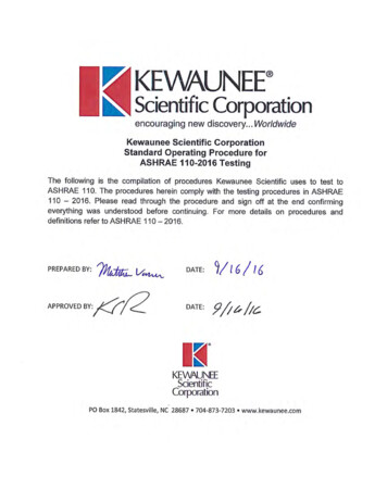
Ultraviolet Air and Surface Treatment62.3Fig. 2 Electromagnetic Spectrum(IESNA 2000)Fig. 3Standardized Germicidal Response FunctionsUV Inactivation of Biological ContaminantsThe focus of this chapter is application of UVC energy to inactivate microorganisms, specifically bacteria, fungi, and viruses onsurfaces and in air streams. The application of UVC for upper-airtreatment generally applies to pathogenic bacteria and viruses.Under some circumstances, these pathogens have the potential to betransmitted throughout the HVAC system.As shown in Table 1, infectious diseases can be transmitted by avariety of means. UVC is effective against microorganisms in the airthat flows through the UVC irradiation field and on irradiated surfaces.As shown in Table 2 and Figure 4, viruses and vegetativebacteria are the generally most susceptible to UV inactivation, followed by Mycobacteria, bacterial spores, and finally fungal spores.Within each group, an individual species may be significantly moreresistant or susceptible, so this ranking should be used only as ageneral guideline. Note that the spore-forming bacteria and fungialso have vegetative forms, which are markedly more susceptible toFig. 4 General Ranking of Susceptibility to UVC Inactivationof Microorganisms by Groupinactivation than are the spore forms. Viruses are a separate case.As a group, their susceptibility to inactivation is even broader thanfor the bacteria or fungi.2.TERMINOLOGYJust as it is customary to express the size of aerosols in micrometersand electrical equipment’s power consumption in watts, regardless ofthe prevailing unit system, it is also customary to express total UVCoutput, UVC irradiance and fluence, and UVC dose using SI units.Multiply I-PBtu/ft2 (International Table)Btu/h · ft2To Obtain I-PByTo Obtain SI1135.65315.46ByμJ/cm2μW/cm2Divide SIBurn-in time. Period of time that UV lamps are powered onbefore being put into service, typically 100 h.
62.42019 ASHRAE Handbook—HVAC Applications (SI)Table 1Modes of Disease TransmissionExposureExamplesDirect contact with an infectedindividualIndirect contact with a contaminatedsurface (fomite)Droplet contactTouching, kissing, sexual contact, contact with oral secretions, or contact with open body lesionsUsually occurs between members of the same household/close friends/familyDoorknobs, handrails, furniture, washroom surfaces, dishes, keyboards, pens, phones, office supplies, children’stoysInfected droplets contact surfaces of eye, nose, or mouthDroplets containing microorganisms generated when an infected person coughs, sneezes, or talksDroplets are too large to be airborne for long periods of time, and quickly settle out of airSize allows them to remain airborne for long periods of timeOrganisms generally hardy (capable of surviving for long periods of time outside the body, resistant to drying)Organisms enter the upper and lower respiratory tractsUsually associated with organisms that infect the digestive systemMicroorganisms enter via ingestion of contaminated food/water and shed in fecesLack of proper hygienic and sanitation practicesTransmission through animalsBite, feces of a vector, contact with outside surface of a vector (e.g., a fly)Airborne droplet nuclei (residue fromevaporated droplets) or other particlescontaining microorganisms 5 μmFecal-oralVectorborneTable 2 Representative Members of Organism GroupsOrganism GroupMember of GroupVegetative BacteriaStaphylococcus aureusStreptococcus pyogenesEscherichia coliPseudomonas aeruginosaSerratia marcescensMycobacterium tuberculosisMycobacterium bovisMycobacterium lepraeBacillus anthracisBacillus cereusBacillus subtilisAspergillus versicolorPenicillium chrysogenumStachybotrys chartarumInfluenza virusesMeaslesSARSSmallpoxMycobacteriaBacterial SporeFungal SporesVirusesCutaneous damage. Any damage to the skin, particularly thatcaused by exposure to UVC energy.Disinfection. Compared to sterilization, a less lethal process ofinactivating microorganisms.Droplet nuclei. Residual viable microorganisms in air, followingevaporation of surrounding moisture. These microscopic particlesare produced when an infected person coughs, sneezes, shouts, orsings. The particles can remain suspended for prolonged periodsand can be carried on normal air currents in a room and beyond toadjacent spaces or areas receiving exhaust air.Erythema (actinic). Reddening of the skin, with or without inflammation, caused by the actinic effect of solar radiation or artificial optical radiation. See CIE (2011) for details. (Nonactinicerythema can be caused by various chemical or physical agents.)Exposure. Being subjected to infectious agents, irradiation, particulates, or chemicals that could have harmful effects.Fluence. Radiant flux passing from all directions through a unitarea, often expressed as J/m2, J/cm2, or (μW · s)/cm2.Irradiance. Power of electromagnetic radiation incident on asurface per unit surface area, typically reported in microwatts persquare centimeter (μW/cm2). See CIE (2011) for details.Mycobacterium tuberculosis. The namesake member of the M.tuberculosis complex of microorganisms, and the most commoncause of tuberculosis (TB) in humans. In some instances, the speciesname refers to the entire M. tuberculosis complex, which includesM. bovis, M. africanum, M. microti, M. canettii, M. caprae, M. pinnipedii, and others.Ocular damage. Any damage to the eye, particularly that causedby exposure to UV energy.Permissible exposure time (PET). Calculated time period thathumans, with unprotected eyes and skin, can be exposed to a givenlevel of UV irradiance without exceeding the NIOSH recommendedexposure limit (REL) or ACGIH Threshold Limit Value (TLV )for UV radiation.Personal protective equipment (PPE). Protective clothing, helmets, goggles, respirators, or other gear designed to protect thewearer from injury from a given hazard, typically used for occupational safety and health purposes.Photokeratitis. Defined by CIE (1993) as corneal inflammationafter overexposure to ultraviolet radiation.Photokeratoconjunctivitis. Inflammation of cornea and conjunctiva after exposure to UV radiation. Exposure to wavelengthsshorter than 320 nm is most effective in causing this condition. Thepeak of the action spectrum is approximately 270 nm. See CIE(1993) for details. Note that different action spectra have been published for photokeratitis and photoconjuctivitis (CIE 1993); however, the latest studies support the use of a single action spectrum forboth ocular effects.Radiometer. An instrument used to measure radiometric quantities, particularly UV irradiance or fluence.Threshold Limit Value (TLV ). An exposure level underwhich most people can work consistently for 8 h a day, day after day,without adverse effects. Used by the ACGIH to designate degree ofexposure to contaminants. TLVs can be expressed as approximatemilligrams of particulate per cubic meter of air (mg/m3). TLVs arelisted either for 8 h as a time-weighted average (TWA) or for 15 minas a short-term exposure limit (STEL).Ultraviolet radiation. Optical radiation with a wavelengthshorter than that of visible radiation. (See CIE [1987] for details.)The range between 100 and 400 nm is commonly subdivided intoUVA: 315 to 400 nmUVB: 280 to 315 nmUVC: 200 to 280 nmVacuum UV 100 to 200 nmUltraviolet germicidal irradiation (UVGI). Ultraviolet radiationthat inactivates microorganisms. UVC energy is generated by germicidal lamps that kill or inactivate microorganisms by emittingradiation predominantly at a wavelength of 253.7 nm.UV dose. Product of UV irradiance and specific exposure time ona given microorganism or surface, typically reported in millijoulesper square centimeter (mJ/cm2).Wavelength. Distance between repeating units of a wave pattern,commonly designated by the Greek letter lambda (λ).
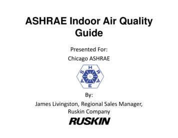
Ultraviolet Air and Surface Treatment3.62.5UVGI AIR TREATMENT SYSTEMSDesign GuidanceEarly guidelines published by General Electric (Buttolph andHaynes 1950), Philips (1985), and Westinghouse (1982) are stillused by many system designers today. First et al. (1999), Kowalski(2003, 2006, 2009), NIOSH (2009), and Riley et al. (1976) mademeaningful advances in the analysis and modeling of UVGI systemsthat improved guidance for system design, yet no consensus guidelines exist that comprehensively address all aspects of UVGI systemdesign required to ensure desired performance.UVC system design today relies on performance data from lamp,ballast, and fixture manufacturers and the experience of systemdesigners. Many equipment manufacturers have methods for estimating the UV dose delivered, which may include using tabulateddata charts, mathematical modeling, and complex formulas. Likemost HVAC components, UVC systems are often oversized toensure performance. This oversizing, though conservative, canpotentially increase equipment and utility costs, and may result inless energy-efficient systems.Although application support for UVC technologies is growingand many successful systems have been installed, “the mostimportant needs in the area of UVGI are industry standards to ratedevices and installations, as well as guidance for installation andmaintenance” (EPA 2017). ASHRAE Technical Committee 2.9,Ultraviolet Air and Surface Treatment, was created in 2003 (initiallyas a Task Group, converted to a standing Technical Committee in2007) in part to address these deficiencies by initiating research programs, preparing Handbook chapters, and serving as the cognizantcommittee for developing the needed standards. So far, two newASHRAE standards have been developed that provide end userswith ratings of equipment performance and aid UVC systemdesigners in selecting appropriate components: ASHRAE Standard 185.1, Method of Testing UV-C Lights forUse in Air-Handling Units or Air Ducts to Inactivate AirborneMicroorganisms, establishes a test method for evaluating the efficacy of UVC lights for their ability to inactivate airborne microorganisms installed inside general ventilation systems. ASHRAE Standard 185.2, Method of Testing UltravioletLamps for Use in HVAC&R Units or Air Ducts to InactivateMicroorganisms on Irradiated Surfaces, establishes a similartest method to measure the intensity of ultraviolet lamps on irradiated surfaces under typical HVAC&R operating conditions.Work is ongoing to initiate round-robin testing between laboratories that can potentially conduct testing on UVC devicesaccording to these new standards. Such testing will generate criticaldata on the repeatability of the testing methods and identify issuesthat must be addressed in updates to the standards.For any application, the ability of UVC to inactivate microorganisms is a function of dose. Dose is the length of time of exposuremultiplied by the irradiance measured in μW/cm2 (see Chapter 17 inthe 2016 ASHRAE Handbook—HVAC Systems and Equipment formore details). A key difference between surface decontaminationand airborne inactivation of organisms is exposure time. In a ductsystem, exposure time is on the order of seconds or fractions of seconds because of the rapid movement of air through the duct. Therefore, the irradiance must be sufficiently high to provide the dosenecessary to inactivate the pathogen in seconds or a fraction of asecond, depending upon the configuration and characteristics of theUVC system.As mentioned previously, organisms differ in their susceptibilityto UVC inactivation. Depending on the application, a public healthor medical professional, microbiologist, or other individual withknowledge of the threat or organisms of concern should be consulted during the design process.Fig. 5Typical Elevation View of Upper-Room UV Applied inHospital Patient RoomUpper-Air UVC Devices (Fixtures)The primary objective of upper-air UVC placement and use is tointerrupt the transmission of airborne infectious pathogens withinthe indoor environment. The source of these infectious organismsmay be infected humans, animals, or bioaerosols introduced for terrorism purposes. Humans are the predominant sources of airborneagents that infect people (ACGIH 1999). The measles and influenzaviruses and the tuberculosis bacterium are three important infectious organisms known to be transmitted indoors by means of airshared, by any means, between infected and susceptible persons.Studies of person-to-person outbreaks indicate at least two transmission patterns: within-room exposure such as in a congregatespace, and transmission beyond a room through corridors and byentrainment in ventilation ductwork, through which air is then recirculated throughout the building. ASHRAE also provides guidanceon protecting buildings from extraordinary incidents in which a bioterror agent is aerosolized into a building (ASHRAE 2003).UVC is used, in combination with other environmental controls,to protect building occupants in all areas of concern (Brickner et al.2003; Kowalski and Bahnfleth 2003). Since the 1930s (Riley andO’Grady 1961; Wells 1955) and continuing to the present day (Firstet al. 2007a, 2007b; Miller et al. 2002; Xu et al. 2003), numerousexperimental studies have demonstrated the efficacy of upper-airUVC. Additionally, evidence of effectiveness has been establishedfor inactivating tuberculosis (Escombe et al. 2009; Mphaphlele etal. 2015), reducing measles transmission in a school, and the interruption of influenza transmission within a hospital (McLean 1961).Various upper-air UVC devices are designed to generate a controlled UVC field above the heads of occupants and to minimizeUVC in the lower, occupied area of the room. Settings appropriateto upper-air UVC placement include congregate spaces, whereunknown and potentially infected persons may share the same spacewith uninfected persons (e.g., a medical waiting room or homelessshelter). Common corridors potentially used by unknown infectedpersons in a medical facility would also benefit from upper-airUVGI fixtures. Upper-air UVC also covers situations whereuntreated recirculated air might enter an occupied space (see Figures 5 and 6 for illustrations of upper-air pathogen control usingUVC). Upper-air UVC is very effective in areas with no, or minimal, ventilation; 2 air changes per hour (ach) equivalency, up to normal recommended levels of 6 ach can be achieved. Ventilationpatterns (natural and mechanical) should promote good air mixingin the space equipped with UVC so that infectious microorganismsencounter the UVC zone and are inactivated, thus reducing the riskof exposure of occupants to airborne infectious agents. Recentstudies that have used natural ventilation and UVC have shown thatupper-air UVC is an effective, low-cost intervention for use in TBinfection control (Escombe et al. 2009; Mphaphlele et al. 2015).Upper-air UVC devices are designed and installed to irradiateonly air in the upper part of the room (Figures 7 and 8). Parametersfor UVC effectiveness include room configuration, UV fixture
62.62019 ASHRAE Handbook—HVAC Applications (SI)Fig. 6 Typical Elevation View Showing UVGI Energy Placeabove Heads of Room Occupants, Maintaining SafetyFig. 8 Upper-Air UVC Devices in Naturally VentilatedCorridor of TB Facility in Brazil(Centers for Disease Control and Prevention)Fig. 7 Upper-Air UVC Treating Congregate Setting(TUSS Project, St. Vincent's Hospital, New York City)placement, and the adequacy of air currents in bringing contaminated air into the upper UV zone. UVC devices should be placedappropriately spaced to accommodate the area, shape, and height ofthe space in which air is to be disinfected. Figures 9 to 11 showexamples of upper-air fixture placement. An upper-air computerbased tool can calculate the average fluence in the upper room(Rudnick et al. 2012; Vincent et al. 2013; Zhang et al. 2012). Additionally, computational fluid dynamics (CFD) is being used tounderstand the interaction between airflow and upper-air UVC(Gilkeson and Noakes 2013; Xu et al. 2013; Zhu et al. 2013).Upper-air UVC devices typically use low-pressure UVC lamps intubular and compact shapes and accommodate a variety of electricalwattages and voltages. Beyond lamp size, shape, and ballasts, fixturesare available in open or restricted energy distribution, depending onthe physical space to be treated. UVC fixtures are selected based onthe floor-to-ceiling height. Ceiling heights above 3 m may allow formore open fixtures, which may be more efficient because they mayallow for a larger irradiation zone. For occupied spaces with lowerceilings (less than 3 m), various louvered upper-air UVC devices(wall-mount, pendant, and corner-mount) are available for use incombinations and are mounted with at least 2.1 m from the floor to thebottom of the fixture. The fixture should be mounted so that its UVenergy is distributed parallel to the plane of the ceiling. Device construction and placement prevent excessive ultraviolet energy fromstriking occupants below. For example, in high-risk areas such asFig. 9 Suggested Layout of UVC Fixtures forPatient Isolation Room(First et al. 1999)corridors of infectious disease wards, a maximum UV irradiationof 0.4 μW/cm2 at eye level is an acceptable engineering guide(Coker et al. 2001). No long-term health effects of UVC exposureat these levels in the lower occupied part of rooms are known. Figure 5 shows a typical elevation and corresponding UV levels, and Figure 6 illustrates typical UVC energy distribution in a room.Application guidance with placement criteria for UV equipmentis provided by Boyce (2003), CDC (2005), CIE (2003), Coker et al.(2001), First et al. (1999), IESNA (2000), and NIOSH (2009). Anexample of the guidance provided by Coker et al. is shown in Table3. Additionally, manufacturer-specific advice on product operationand placement should be followed. A new computer-aided lightingsoftware program is being modified to help automate the placementof fixtures, and to calculate the uniformity and average UV provided(Brickner et al. 2009). Upper-air UVC fixtures that are typicallyused in developed countries are often cost-prohibitive for use in lessdeveloped parts of the world. International guidance is needed tounderstand best practice for UVC application in the developing
Ultraviolet Air and Surface Treatment62.7Table 3 Suggested UVC Fixture Mounting HeightsWall-Mounted Fixtures*Beam patternMinimum ceiling heightFixture mounted heightIdeal UV-C intensity for effective disinfectionCeiling-Mounted Figures*Corner MountWall MountPendantPendant with Fan90 2.44 m2.1 m 10 μW/cm2180 2.44 m2.1 m 10 μW/cm2360 2.89 m2.4 m 10 μW/cm2360 2.89 m2.4 m 10 μW/cm2Source: Coker et al. (2001)*Appropriately designed UV fixtures are available for all locations. Only the most commonly used have been included in the table.Fig. 10 Upper-Air UVC Devices with 180 Emission ProfileCovering Corridors(First et al. 1999)world where extensive drug-resistant TB is an increasing globalthreat (Nardell et al. 2013).Some upper-air installations rely on air convection and mixing tomove air from the lower to the upper portion of the room, where itcan be irradiated and airborne microorganisms inactivated (Kethleyand Branc 1972). The overall effectiveness of upper-air UVC systems improves significantly when the air in the space can be wellmixed. Although convection air currents created by occupants andequipment can provide adequate air circulation in some settings,mechanical ventilation systems that maximize air mixing are preferable. If mechanical ventilation is not possible, fans can be placedin the room to enhance mixing. Many fixtures incorporate a safetyswitch that breaks the circuit when fixtures are opened for servicingand should contain baffles or louvers appropriately positioned todirect UV irradiation to the upper air space. Baffles and louvers mustnever be bent or deformed.A UVC installation that produces a maintained, uniform distribution of UV irradiance averaging between 30 and 50 μW/cm2 iseffective in inactivating most airborne droplet nuclei containingmycobacteria, and is presumably effective against viruses as well(First et al. 2007a, 2007b; Miller et al. 2002; Xu et al. 2003). Beyond UVC irradiance, effectiveness of upper-air UVC is related toair mixing, relative humidity, and the inherent characteristics ofthe pathogenic organisms being addressed (Ka et al. 2004; Ko etal. 2000; Rudnick 2007). Effectiveness can improve greatly withwell-mixed air (First et al. 2007a, 2007b; Miller et al. 2002; Rileyand Permutt 1971; Riley et al. 1971), so ventilation systems thatmaximize air mixing receive the greatest benefit from upper-airUVC. Relative humidity should be less than 60%; levels over 80% rhmay reduce effectiveness (Kujundzic et al. 2007; Xu et al. 2003).Depending on the disinfection goals, upper-air devices should beoperated similarly to in-duct UVC systems. Systems designed to reduce or eliminate the spread of airborne infectious diseases in buildings with continuous occupancy and/or with immunocompromisedpopulations should be operated 24 h per day, 7 days per week. Upperair systems designed for improved indoor air quality installed inmore traditional commercial buildings may be operatedFig. 11 Example Upper-Air UVGI Layout for AMeeting Roomintermittently, or powered on during hours of normal building occupancy and powered off when the facility is empty. This may provideacceptable indoor air quality during periods of building occupancy,simu
62.4 2019 ASHRAE Handbook—HVAC Applications (SI) Cutaneous damage. Any damage to the skin, particularly that caused by exposure to UVC energy. Disinfection. Compared to sterilization, a less lethal process of inactivating microorganisms. Droplet nuclei. Residual viable microorga nisms in air, following evaporation of surrounding moisture.