Transcription
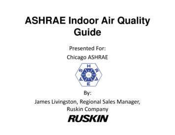
ASHRAE Indoor Air QualityGuidePresented For:Chicago ASHRAEBy:James Livingston, Regional Sales Manager,Ruskin Company1
Purpose of Presentation Comment on ASHRAE IAQGuide topics as related to aircontrol devices Provide information on thefunction and benefits of thesedevices Provide advice on theirapplication2
Presentation AgendaIAQ Guide BasicsObjectives1 Design & Construction2 Control Moisture4 Moisture in HVAC6 Capture/ExhaustContaminants7 Reduce Contaminants8 Advanced VentilationApproaches3
Purpose of IAQ Guide Provide advice on how provide good IAQvia means that are:– Cost effective– Practical– Currently available– Technologically sound– Sustainable– Goal: Increased usage & IAQ!4
Guide Approach 8 “Objectives” Objectives address components ofbuilding IAQ Each Objective contains individual“Strategies” to help achieve the Objective Benefits designers, constructors, ownersand facility managers5
Scope of IAQ Guide Buildings covered:– Commercial & institutional OfficeRetailEducationalLodgingPublic assembly6
Scope of IAQ Guide Buildings not covered:––––––––KitchensMedical procedure roomsNatatoriumsCold buildingsLaboratoryIndustrialResidentialChemical storage7
Why IAQ? Health & well being of occupants Financial success & sustainability ofbuilding8
Common Sources of Poor IAQ Two Basic Categories–Gaseous –Radon, C02, chemical vapors, etc.Biological (with 2 subcategories) Microbial– Bacteria, molds, mildews, viruses, dustmites, animal dander, etc.Particulate–Dust, pollen, building material fibers,process byproduct (such as saw dust), etc.“THE SOLUTION TOPOLLUTION IS DILUTION”W. K.
Health Issues Increased allergy & asthma symptomsColds & infectionsCarbon monoxide poisoningLegionnaires’ diseaseLung cancer from Radon exposure10
Financial Impact Repairs or modifications to correct issuesPotential temporary building closureDifficulty in renting spacesLegal action due to sick building or otherissues11
A Different Way Of Thinking Traditional high priority features includecost, space, aesthetics, etc. Make IAQ a priority in the beginning! Early discussions & strategies by all parties Improving IAQ after the fact is difficult andsometimes impossible12
Objective 1 Manage the Design &Construction Process to AchieveGood IAQ Strategy 1.1 Traditional Design13
Objective 1 Strategy 1.1 Integrated Design14
Objective 1 Strategy 1.2 Commissioning– Not just post-construction– Employ a Commissioning Authority (CxA) forpre-design and during construction– Ensure the design meets ownersrequirements and is being constructedcorrectly15
Objective 1 Strategy 1.3 Selecting HVAC Systems– Use environmentally-friendly & energy efficientsystems when possible– Displacement ventilation– If conventional means are used (CV, VAV, etc.),be sure good IAQ practices are used (62.1ventilation for example).16
Objective 1 Strategy 1.5 Effective Operation &Maintenance– O&M can be just as important as design &construction– Expected level of owner’s O&M efforts?– Consider O&M during design & construction– Provide documentation & training17
Objective 2 Control Moisture inBuilding Assemblies Moisture is a common cause of IAQ problems andresponsible for the most costly litigation andremediation Thermal bridging enables interior frost build-up &condensation Condensation liquid can travel through capillaryaction to inaccessible locations18
Objective 2 Strategy 2.2 Limit Condensation of WaterVapor within the Building Envelope and onInterior Surfaces– Use Thermally Efficient (Insulated) ControlDampers at outside air intakes19
Strategy 2.2 Why use Thermally EfficientDampers?– Reduce condensation toprevent bacteria, mold,mildew– Thermally broken to preventfrost build-up– Lessen leakage into or out ofspace Generally Class 1 leakage – 4cfm/ft² at 1” w.g.
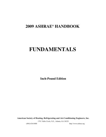
AMCA 500-D Section 6.9 Thermal Efficiency Test Test setup Figure 5.10 Damper tested in bothairflow directions 2 F Steady StateTemperature for a period of10 minutes Applied torque
AMCA 500-D V-groove referencedamper 9 cfm per squarefoot at 1” w.c. How much moreefficient is the testdamper whencompared to thereference damper?
Thermally Efficient Damper Features Insulated & thermallybroken blades Blade & jamb seals forlow leakage Thermally brokenframes Non-metallic bearings
Thermally Efficient Damper Performance AMCA Standard 500-D– AMCA certified leakage– AMCA certified performance– AMCA certified Thermal Efficiency
Objective 2 Strategy 2.3 Maintain Proper BuildingPressurization– Building pressure affects moisture infiltrationand exfiltration– Negative pressure in hot, humid conditionspromotes moisture infiltration into spaces– Positive pressure in humid spaces increasescondensation buildup within envelope25
Strategy 2.3 Pressurization often is not consistentthroughout building due to:– Stack effect– Wind speed & direction– Temperature– HVAC supply & exhaust rates26
Strategy 2.3 Airflow measuring stations can assist withpressurization27
Pick the Product for the Application Use Electronic Air Flow Measurement forvery low velocities and large openings Use Velocity Pressure Measurement for highvelocities or small openings.
Electronic Airflow Measuring Thermistors, heated mass flow sensors,hot film anemometers, etc.– Measures energy to heat element– Low velocities – as little as 0 fpm29
Velocity Pressure Airflow Measuring Differential Pressure– Minimum 300 fpmTotal Pressure ChamberPtPsStatic Pressure ChamberPv Pt - Ps
Locations For Airflow Measuring Stations
Suggestions for Measuring OutsideAirVAV & CV Systems Air measuringstation w/ controldamper built-in Damper control ismanual or by BASDCV Systems Air measuringstation with built-incontrol damper andcontrol system Control systemmaintains CFM setpoint as fans scrollup and downAny system, limitedspace Air measuringcombined withoutside air louver Can be as little as4” total depth32
Suggestions for Measuring SupplyAirFan inlet Highest velocitypoint in the system Total system supplyairflowRetrofit – single flooror pressure area Probes or stations Can install as closeas 4” in front ofexisting dampersNew construction –single floor or pressurearea Air measuringstation w/ controldamper built-in Damper control ismanual or by BAS33
Suggestions for Measuring ReturnAirRetrofit – single flooror pressure area Probes or stations Can install as closeas 4” in front ofexisting dampersNew construction –single floor or pressurearea Air measuringstation w/ controldamper built-in Damper control ismanual or by BAS34
Suggestions for Measuring ExhaustAirUse velocity pressure probesor stations Works well with highvelocity exhaust airflow Much less expensive thanelectronic airflow stations35
Objective 4 Control Moisture &Contaminants Related toMechanical Systems Strategy 4.1 Control Moisture and Dirt in AirHandling Systems– Fungi & bacteria are normally present on buildinginterior surfaces, including HVAC components– Microorganism growth in HVAC system results inmalodors, nasal & throat irritation and buildingrelated illnesses36
Strategy 4.1 Outside air louvers can prevent rainpenetrationLouvers37
Louvers With Plenum Behind38
Water Penetration39
Sloped Plenum Detail40
Strategy 4.1 Traditional louvers provide protectionfrom non-storm rain Wind Driven Rain Resistant louver providestorm condition protection Let’s look at the differences 41
Strategy 4.1 Traditional Louvers:– Horizontal blades– Drain Gutters– Wide Spacing– High Free Area– Low Cost– Stops some rain– Not effective in storms42
Strategy 4.1 Traditional louver sizing– AMCA Water Penetration test – BeginningPoint of Water Penetration free area velocity(FAV)– Determine design FAV considering AMCA testdata– CFM/FAV Total Free Area required– Reference louver Free Area Guide todetermine appropriate louver size43
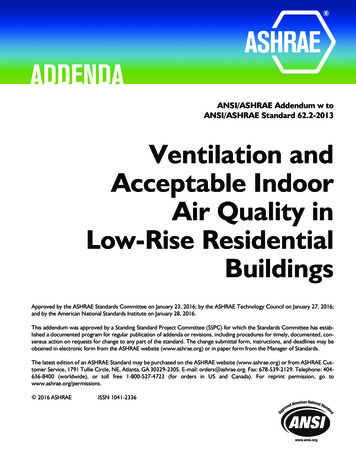
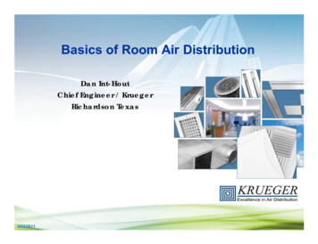
Standard 500-L Louvers5.6 Water PenetrationAir ExhaustWaterdrop ManifoldWetted Wall ManifoldWaterDropletsTest UnitAir Entrainedinto chamberthrough louverExhaustFanAir FlowMeasurementCollectionZone“Still Air”Condition!
Standard 500-L LouversTest Conditions 48” x 48” size 15 minute intervals Manifold (raindrops) - 4” perhour (3.15 gal/15 min) Wetted wall - .25 gpm (3.75gallons/15 min) Ventilation airflow only – nowind 1250 fpm max free areavelocity
AMCA “Still Air” Water Test
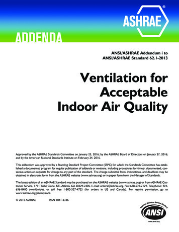
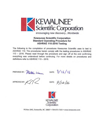
Water Penetration GraphBeginning PointOf WaterPenetration: .01oz/ft² at 1,023fpm Free AreaVelocity.01 oz./ft²of freearea
“Still Air” Test with Non-drainable Louver
Traditional Louvers Where to use:– Properly drained applications Sloped plenums & ductwork Floor drains– Protected areas (overhangs, barriers, interior,non-prevailing wind elevations)– “Screen” applications (vision barriers) Sizing– Use Safety Factor (15% to 20% min) Does NOT stop storm rain
Traditional Drainable Louver29 mph wind, 3”/hr rain, 1,000 fpm intake velocity
New Louver Technology Wind Driven Rain Louvers– Horizontal or Vertical blades– Drain Gutters on horizontal– Hooks on vertical– Close spacing– Lower Free Area– Higher Velocity– Effective in storms51
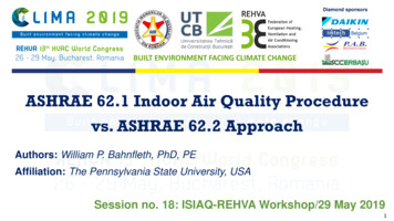
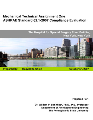
Std 500-L Wind Driven Rain Test5.11 Water Rejection Wind Driven RainAir ExhaustTest LouverRain WaterDischargeNozzlesWind/RainMachineWind DrivenRain plusAir EntrainedInto ChamberThrough LouverExhaust FanCollection Zone52
Std 500-L Wind Driven RainTest Rejection Effectiveness ClassesA 99% to 100%B 95% to 98.9%C 94.9% to 80%D below 80% (std. louvers)3” rain/29 mph wind8” rain/50 mph wind53
Wind Driven Rain Louver29 mph wind, 3”/hr rain, 2,000 fpm intake velocity
Rear view, 29 mph wind, 3”/hr rain, 2,000 fpm intake velocity
How Much Water Is Applied? 3” Per Hour Rain On 1m X 1m 21 Gallons Applied Over 1 Hr.– Class A (99% or better) allows 27 fl. oz penetration– Class D (80% or worse) allows over 4 gallons– Std Louvers (60% or lower) - over 7 gallons
Wind Driven Rain Louver Benefits Prevent rain infiltration– Lessens interior water damage & mold growth– Helps keep walls & floors dry– Helps keep filters dry– Excellent for Penthouses Allow higher intake velocities– Use smaller louvers! Reduce future problems & liability
Wind Driven Rain LouversHorizontal blade models40% - 50%free area2” to 8” deepClass A @800 to 1200fpmModerate pTraditionalappearanceVertical blade models40% - 45%free area3” to 7” deepClass A @1500 to 2100fpmLow pBestperformance58
Sizing Example 48” x 48” & 7,000 cfm 6” Traditional710 fpm.07” p60% Wind DrivenRain Effectiveness(29 mph)Cost 1.0 5” Horizontal WDR1,002 fpm.16” p99.8% Wind DrivenRain Effectiveness(29 mph)Cost 1.7 6” Vertical WDR1,030 fpm.09” p99.8% Wind DrivenRain Effectiveness (50mph)Cost 2.748” x 36” (25% smaller)1,488 fpm.18” p99.8% Wind Driven RainEffectiveness (50 mph)Cost 2.3
Rooftop IntakesTraditional style, allowsrain penetrationWind Driven Rain Design,prevents rain penetration
What About Snow?61
Suggestion for Stopping SnowPenetration Heated screen behind louver Prevents snow blowing intoductwork Reasonable pressure drop Relatively slow airflow - 350 FPMFace area velocity.
Objective 7 Reduce ContaminantConcentrations through Ventilation,Filtration and Air Cleaning First goal is to reducing contaminant sources,then capturing & exhausting Remaining contaminants should be– Diluted with ventilation air, or– Reduced by filtration and gas-phased air cleaning(FAC)63
Strategy 7.2 Continuously Monitorand Control Outdoor Air Delivery Fixed minimum outdoor air dampers may notprovide optimum control of intake CFM,particularly in VAV systems Over-ventilation is common now – estimated30% annual savings in U.S. building energy costsif ventilation per standards is maintained64
Suggestion for Maintaining ProperOutdoor Air Intake Levels Use air measuring station with built-in controldamper and control system to maintain CFM setpoint65
Air Measuring & Control Stations Advantages– System automatically modulatesdamper to maintain CFM– Can be used as minimum outside airdamper only (overridden wheneconomizer damper opens), or– Can be used as entire outside airdamper66
Pressure Signal Charttext Air Measuring & Control DamperDocumentation I/O Chart Provided w/ unit Calibration Certificate 0 - 10VDC Input - CFM Setpoint 0 – 10 VDC Output - Measured CFM Alarm when CFM falls below setpoint
Strategy 7.2 Continuously Monitorand Control Outdoor Air Delivery Proper placement of airflow stations is critical Installing too close to an elbow or otherdisrupting feature can affect performance68
Air Measurement Station Placements for Acceptable Installations
Air Measurement Station Placements for Acceptable InstallationsAir Measurement should be in the Mechanical Spec!
Air Measurement Station Placements for Acceptable Installations5D90 DEGREE UNVANED ELBOW1D
Strategy 7.2 Continuously Monitorand Control Outdoor Air Delivery Consider using airflowmeasuring sensorsbetween fixed louverblades– Higher velocity, betteraccuracy
Accuracy Considerations:Outside Air Measurement AdvantageOutsideAir20,000 CFM supply air measured 1,000 CFM @ 5% accuracy (S.A.)16,000 CFM return air measured 800 CFM @ 5% accuracy (R.A.)Air FlowSensingStationsTHE DIFFERENCECould be off by 1,800 CFMVersus measurement at the intake4,000 CFM @ 5% accuracy (O.A.) 200 CFM @ 5% accuracy (O.A.)
Objective 8 Apply More AdvancedVentilation Approaches Strategy 8.2 Use Energy Recovery VentilationWhere Appropriate– Required by ASHRAE 90.1 2007 & 2010 in somecases74
Code Driven RequirementsASHRAE 90.1 2007 Energy StandardEnergy recovery is required on individual fansystems that are:5000 cfm or greater, andOutside air accounts for 70% or more of the designsupply air quantityEnergy recovery system shall have 50%effectiveness:Change in enthalpy equal to 50% of the differencebetween outdoor air and return air at designconditions
Status of Code Adoption: Commercialwww.energycodes.gov/adoption/statesAs of February 2013Most States are Expected to Adopt 90.1 2010 by End of 2013!
DOE Climate Zone Map – for 90.1Helena MTDuluth, MNBurlington, VTBoise, IDChicago, ILSalem, ORBaltimore MDSan Francisco CAPhoenix, AZEl Paso, TXMiami FLMemphis TNFigure B-1Albuquerque, NMHouston, TX
How do Climate Zones affect ERV?ASHRAE 90.1 2010 states:6.5.6.1 Exhaust Air Energy Recovery. Each fan system shall have an energyrecovery system when the system’s supply air flow rate exceeds the value listedin table 6.5.6.1 based on the climate zone and percentage of outdoor air flow rateat design conditions.
ASHRAE 189.1 Standard Stretch standard for energy efficiency “Glimpse” of the future of 90.1 Currently being specified for somegovernment buildings Requires even more energy recovery As low as 10% outside air requires energyrecovery in some cases The energy recovery effectiveness shall be60%
Energy Recovery ERV – Latent Recovery– Energy Recovery Wheels– Fixed Plate w/ Latent Transfer HRV – Sensible Only (no latent)– Fixed Plate– Heat Pipe– Runaround Loops80
Wheel ERV’s – How They WorkWheel Rotates between theReturn Air and the Outdoor AirAirstreamsReturn Air Temperature andHumidity is absorbed onto theDesiccant WheelOutdoor Air is tempered(Heated/Cooled) as it flowsacross the WheelOutdoor Air HumidityDecreases or Increases as airflows across the Wheel
Exhaust Air Transfer RatioEATR is the % of air being exhausted fromthe occupied space that leaks around theERV wheel and re-enters occupied space.Importance: Per ASHRAE 62.1
Dedicated Duct System
Ducted to Rooftop Unit
Common ERV ConfigurationsStand AloneUnitizedTypically 300 to 12,000 CFM
Small ERV’s – 150 to 1000 CFMOnly 18” to 22” tall!
Example of small ERV application
Small ERV Installation
Questions?89
Thank You!90
ASHRAE Indoor Air Quality Guide Presented For: Chicago ASHRAE By: James Livingston, Regional Sales Manager, Ruskin Company 1. Purpose of Presentation Comment on ASHRAE IAQ Guide topics as related to air control devices Provide