Transcription
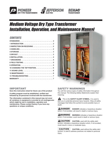
Design Guide DG009004ENEffective November 2020Low-voltage power distribution and control systems Transformers Low-voltage dry-typebuck-boost transformersContentsGeneral Description. . . . . . . . . . . . . . . . . . . . . . . . . . . . 19.4-2Overview . . . . . . . . . . . . . . . . . . . . . . . . . . . . . . . . . . . 19.4-2How to Select a Buck-Boost Transformer . . . . . . . . . . 19.4-3Technical Data . . . . . . . . . . . . . . . . . . . . . . . . . . . . . . . .Selection Tables. . . . . . . . . . . . . . . . . . . . . . . . . . . . . .Transformer Selection Information. . . . . . . . . . . . . . . .Wiring Diagrams . . . . . . . . . . . . . . . . . . . . . . . . . . . . .Dimensions . . . . . . . . . . . . . . . . . . . . . . . . . . . . . . . . .19.4-419.4-519.4-2519.4-2619.4-28Application Information . . . . . . . . . . . . . . . . . . . . . . . .Standards and Certifications . . . . . . . . . . . . . . . . . . . .Glossary of Transformer Terms. . . . . . . . . . . . . . . . . . .Frequently Asked Questions About Transformers . . . .19.4-2919.4-2919.4-3019.4-33More about this productEaton.com/transformersComplete library of design guidesEaton.com/designguides
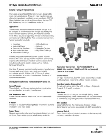
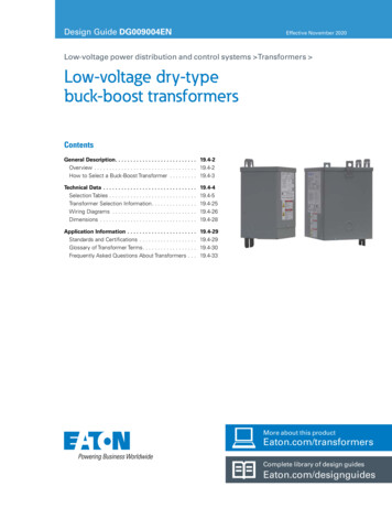
Design Guide DG009004ENLow-Voltage Dry-TypeBuck-Boost TransformersGeneral DescriptionOverviewEffective November 202019.4-2Types EP, EPT Eaton’s buck-boost transformers areideally suited to applications where theavailable voltage needs to be slightlyincreased (“boosted”) or decreased(“bucked”) to be used in a specificapplication. When buck-boosttransformers are wired as autotransformers, they can be used toaccomplish this bucking or boostingof voltage. Buck-boost transformersare single-phase encapsulatedtransformers and are available inthree voltage combinations.120 x 240–12/24120 x 240–16/32 240 x 480–24/48 Buck-boost transformers are availablein ratings 0.05 kVA through 7.5 kVA.These transformers can also be usedat their nameplate voltages forapplications such as low-voltageinterior or landscape lighting.Encapsulated designSuitable for indoor or outdoorapplicationsTotally enclosed, non-ventilatedenclosuresEnclosures are NEMAT 3R ratedMountable in any position indoorsand upright-only outdoors180 ºC insulation system115 C rise standard; 80 C rise optionalAvailable in single-phase ratingsthrough 7.5 kVAEncapsulated transformers, such asbuck-boost and low-voltage lightingtransformers, are specifically excludedfrom the scope of U.S. DOE energyefficiency requirementsApplication DescriptionA buck-boost transformer is used toprovide an economical method ofcorrecting a lower or higher voltage ratingmore suitable for efficient operation ofelectrical equipment. Type EP buck-boosttransformers are small kVA, single-phasetransformers with dual primary and dualsecondary windings, and are usuallyconnected as autotransformers by usingone unit for single-phase applications andeither two or three units banked forthree-phase operation. They are primarilyused for motor operation and should notbe used for motor control circuits, tocorrect fluctuating line voltage or toobtain a neutral on a delta system.Buck-boost transformers are ideallysuited for use with low-voltage lightingsystems, such as outdoor lighting.Features, Benefits and Functions60 Hz operation600 volt class insulation Short-term overload capability asrequired by ANSI Meet NEMA ST-20 sound levels Standards and Certifications ULT listedCSAT certifiedIndustry StandardsAll Eaton dry-type distributiontransformers are built and tested inaccordance with applicable NEMA,ANSI and IEEET Standards. All 600 Vclass transformers are UL listed unlessotherwise noted.Seismically QualifiedEaton-manufactured dry-type distributiontransformers are seismically qualified,and exceed requirements of theInternational Building Code (IBC) andCalifornia Code Title 24.EATON www.eaton.com
Design Guide DG009004ENLow-Voltage Dry-TypeBuck-Boost TransformersGeneral DescriptionHow to Select aBuck-Boost TransformerFor quick selection data, refer to the tableson this and the following pages.Selection RequirementsYou should have the followinginformation before selecting abuck-boost transformer.Line VoltageEffective November 202019.4-3Load Amperes or Load kVA5-Step SelectorYou do not need to know both—oneor the other is sufficient for selectionpurposes. This information usually canbe found on the nameplate of theequipment that you want to operate.The tables that follow will simplify theselection of the buck-boost transformers.There are no calculations needed; simplyfollow these five steps:FrequencyThe supply line frequency must be thesame as the frequency of the equipmentto be operated—Eaton’s buck-boosttransformers operate at 60 Hz only.The voltage that you want to buck(decrease) or boost (increase). This canbe found by measuring the supply linevoltage with a voltmeter.PhaseLoad VoltageTransformer InterconnectionThe voltage at which your equipment isdesigned to operate. This is listed on thenameplate of the load equipment.The supply line should be the same asthe equipment to be operated—eithersingle- or three-phase.For three-phase applications,interconnections of transformers shouldbe made in a junction box. Two or threetransformers may be used depending onan open delta (2) or wye (3) connection.1. Refer to the table having the sameoutput voltage as the equipment youwant to operate. For example, if you areinstalling a 240 V 6 kVA single-phaseload use selection table on the page.2. Select the available line voltage acrossthe top of the chart that is closest tothe actual supply voltage. Therefore,for example, if the available linevoltage is 213 V, use the 212 V column.3. Read down the column until youreach an output kVA or amps ratingequal to or greater than the loadrequirements. Since 6 kVA, in theexample, is not listed, use the nexthigher rating, or 7.5 kVA.4. Read across to the far left columns forthe catalog number and quantity oftransformers for your application. Inthis case, you will need one (1) catalognumber S10N06P01P.5. Connect the buck-boost transformer(s)you have selected in accordance withthe connection diagram specified atthe bottom of the available linevoltage column. In this example,Diagram “F” would be used.Note: For single-phase connections andthree-phase open delta connections, inputsand outputs may be reversed. kVA capacityremains constant.EATON www.eaton.com
Design Guide DG009004ENLow-Voltage Dry-TypeBuck-Boost TransformersTechnical DataEffective November 202019.4-4FrequencyEnclosuresSound LevelsEaton buck-boost transformers aredesigned for 60 Hz operation.Eaton encapsulated buck-boosttransformers use a NEMA 3R ratedenclosure.All Eaton 600 volt class general-purposedry-type distribution transformers aredesigned to meet NEMA ST-20 soundlevels listed here. These are the soundlevels measured in a soundproofenvironment. Actual sound levelsmeasured at an installation will likelybe higher due to electrical connectionsand environmental conditions. Lowersound levels are available and should bespecified when the transformer is goingto be installed in an area where soundmay be a concern.Overload CapabilityShort-term overload is designed intotransformers as required by ANSI.Dry-type distribution transformers willdeliver 200% nameplate load for one-halfhour, 150% load for one hour, and 125%load for four hours without beingdamaged, provided that a constant 50%load precedes and follows the overload.See ANSI C57.96-01.250 for additionallimitations.Continuous overload capacity is notdeliberately designed into a transformerbecause the design objective is to bewithin the allowed winding temperaturerise with nameplate loading.Insulation System andTemperature RiseThe design life of transformers havingdifferent insulation systems is the same;the lower temperature systems aredesigned for the same life as the highertemperature systems.Eaton’s encapsulated transformers aremanufactured using a 180 C insulationsystem. Required performance is obtainedwithout exceeding the insulation systemrating at rated temperature rise in a 40 Cmaximum ambient, with an averageambient temperature of 30 C over a24-hour period.Winding TerminationsPrimary and secondary windings areterminated in the wiring compartment.Encapsulated units have copper leads orstabs brought out for connections. Lugsare not supplied with these transformers.Eaton recommends that external cablesbe rated 90 C (sized at 75 C ampacity)for encapsulated designs.Series-Multiple WindingsSeries-multiple windings consist of twosimilar coils in each winding that can beconnected in series or parallel (multiple).Transformers with series-multiplewindings are designated with an “x” or“/” between the voltage ratings, such asvoltages of “120/240” or “240 x 480.”Table 19.4-1. Encapsulated Sound LevelkVA RangeNEMA ST-20 AverageSound Level, dBUp to 9.045If the series-multiple winding isdesignated by an “x,” the winding can beconnected only for a series or parallel.With the “/” designation, a mid-pointalso becomes available in addition tothe series or parallel connection. As anexample, a 120 x 240 winding can beconnected for either 120 (parallel) or240 (series), but a 120/240 windingcan be connected for 120 (parallel),240 (series) or 240 with a 120 mid-point.All insulation materials are flameretardant and do not support combustionas defined in ASTM Standard TestMethod D635.EATON www.eaton.com
Design Guide DG009004ENLow-Voltage Dry-TypeBuck-Boost TransformersTechnical DataEffective November 202019.4-5Selection TablesTable 19.4-2. Single-Phase 115 V Output Required, 60 HzUnitsRequired aUnitkVAInput Available Voltage84 Output AmpskVA91 OutputkVAAmps96 Output AmpskVA100 OutputkVAAmps102 n Diagram bDBBCAAdditional wiring trough may be required.b Refer to Page 19.4-26 for buck-boost wiring diagrams.Rated Output VoltageOutput voltage for lower input voltage can be found by:x Input Actual Voltage Output New Voltage.Rated Input VoltageActual Output VoltageOutput kVA available at reduced input voltage can be found by:x Output kVA New kVA Rating.Rated Input VoltageFrame drawings/dimensions information begins on Page 19.4-28.aEATON www.eaton.com
Design Guide DG009004ENLow-Voltage Dry-TypeBuck-Boost TransformersTechnical DataEffective November 202019.4-6Table 19.4-2. Single-Phase 115 V Output Required, 60 Hz, continuedUnitsRequired aUnitkVAInput Available nection Diagram bAAABBAdditional wiring trough may be required.b Refer to Page 19.4-26 for buck-boost wiring diagrams.Rated Output VoltageOutput voltage for lower input voltage can be found by:x Input Actual Voltage Output New Voltage.Rated Input VoltageaOutput kVA available at reduced input voltage can be found by:Actual Output Voltagex Output kVA New kVA Rating.Rated Input VoltageFrame drawings/dimensions information begins on Page 19.4-28EATON www.eaton.com
Design Guide DG009004ENLow-Voltage Dry-TypeBuck-Boost TransformersTechnical DataEffective November 202019.4-7Table 19.4-3. Single-Phase 120 V Output Required, 60 HzUnitsRequired —
01.01.2016 · reach an output kVA or amps rating equal to or greater than the load requirements. Since 6 kVA, in the example, is not listed, use the next higher rating, or 7.5 kVA. 4. Read across to the far left columns for the catalog number and quantity of transformers for your application. In this case, you will need one (1) catalog number S10N06P01P. 5. Connect the buck-boost transformer(s) you have .