Transcription
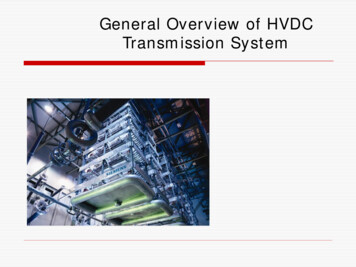
IJSRD - International Journal for Scientific Research & Development Vol. 3, Issue 05, 2015 ISSN (online): 2321-0613Modeling and Simulation of HVDC and HVAC Transmission LineAshwini Kumar1 Dr. A. K. Sharma21M.E. Student 2Professor1,2Department of Electrical Engineering1,2Jabalpur Engineering College, Jabalpur, (M.P.), IndiaAbstract— This paper focuses on modeling and simulationof HVDC and HVAC transmission system. The planning,design and operation of power system requires the detailedstudy of various options and prediction of the systemperformance. The analysis of HVDC and HVAC systemrequires the development of appropriate system models. Ingeneral, the system models are nonlinear and time varyingwith power electronics controllers, the control action is atdiscrete times and sampled data models have beensuggested. HVDC simulators have been used for studies inreal time involving actual converter controls. Recentadvances in digital signal processing technology andapplications of parallel processing techniques have resultedin speeding up computations and carrying out simulation inreal time. This has led to the development of Real TimeDigital Simulators which are expected to replace physicalsimulators. The system models are constructed fromassembling the component models and identifying theinterfaces between the various components. In this paper,we will primarily concentrate on the modelling andsimulation of HVDC and HVAC system and hence will bediscussed briefly. This entire system and controlmechanisms are modelled in MATLAB/SIMULINKenvironment.Key words: HVDC Transmission, Thyrister Converter,HVAC Transmission, Compensator, Modelling, SimulationI. INTRODUCTIONHVDC and HVAC transmission systems are planned,designed and installed to give ensure performance lowlosses, high availability, specified control characteristics etc.System studies are essential part of the project schedule.Modeling and simulation are used to system studies. Systemstudies are performed for analysis, preliminary design,improvements in design, finalising the design, finalisingequipment specifications, control criteria. System studiesalso include simulating the various conditions to comparethe anticipated performance vis-à-vis actual performanceetc. Modeling and simulation are essential with respect todynamic performance characteristics. Modling andsimulation is the first and most important part in the projecttime schedule. Before the start of design of the equipmentsand plants, the details about stresses occurring duringnormal, dynamic and abnormal conditions are to be knownaccurately. The specifications are finalised on the basis ofpredicted stresses. The control characteristics are also to bedetermined and verified. Modeling and simulation are theonly tool for predicting accurately the system performanceunder various operating conditions or when subjected tocertain disturbances. For large systems a great number ofvarious case studies have to be carried out and there is astrong incentive to keep the costs and time required to carryout these studies minimum.This paper is organized as section I givesintroduction of the paper. Section II of this paper gives abrief introduction about the HVDC system model. SectionIII gives description of how the HVDC system is modeled inthe simulation software. Section IV of this paper gives abrief introduction about the HVAC system model. Section Vgives description of how the HVAC system is modeled inthe simulation software. Section VI shows the simulationresults of the model and it is followed by conclusion.II. HVDC TRANSMISSION SYSTEMThe HVDC system is generally used to interconnect twoasynchronous AC systems. Sending end AC system, AC isconverted to DC using rectifier and this DC is given toinverter and again converted to AC such that it meets therating of the receiving end AC system. In transmissionsystem, the converted DC power is send through cables inany DC link configuration. HVDC links may be broadlyclassified such as monopolar, bipolar and homopolar.Rectifier and inverter are the converters they perform ac/dcand dc/ac conversion which are designed by using deviceslike IGBT’s, thyristors, GTO’s etc. and they require pulsesfor operation. In this paper, a monopolar HVDC system ismodeled along with transmission line of certain distancewhich is of over head type. For the transmission line,smoothing reactors are placed between the converter andcable in order to arrest the sudden changes in DC current.The AC systems are asynchronous and are altered to acommon AC voltage using transformers at both AC systems.These AC voltages are converted to DC at one end, by therectifier which is designed using thyristors. Similarly atother end, DC is converted to AC using inverter. Foroperation of these thyristors, firing pulses should be given atproper time intervals which require computations andmeasurements. The values required are measured and sent tothe controllers which produce firing pulses. Thesecontrollers are designed based on the characteristics of theconverters. The control schemes of the converters areexplained in detail in further sections. This entire model ismodeled and simulated in the MATLAB/SIMULINKsoftware.The HVDC system [2] schematic diagram modeledin this paper is shown in Fig.1.A. AC sideThe ac sides of the system consist of AC supply network,filters and transformers. The AC supply network is designedas a Thevenin’s equivalent voltage source along withequivalent source impedance. AC filters are used to absorbharmonics in the system and also to supply reactive powercompensation. In order to supply power to two converters,transformers having two different configurations are used.They are one with grounded Wye – Wyeconnection and the other with grounded Wye – Deltaconnection at both AC systems.All rights reserved by www.ijsrd.com607
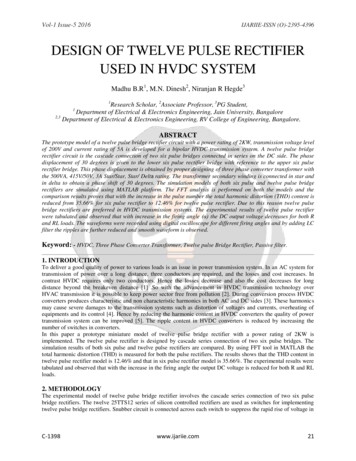
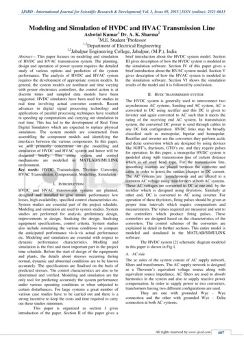
Modeling and Simulation of HVDC and HVAC Transmission Line(IJSRD/Vol. 3/Issue 05/2015/141)B. DC sideThe dc side of the system consists of smoothing reactors andtransmission line of certain distance. These smoothingreactors are used to avoid sudden changes in DC current.C. ConverterThe converter stations are three phase, 12 pulse bridgecircuits, which is formed by connecting two 6 – pulsebridges in series at both sides. The bridge configuration isVoltage Source Converters (VSC) type and it is constructedusing thyristors which have (di/dt) limiting inductor. Thiseach thyristor has a series RC snubber circuit in parallelwith it.Fig. 1: Schematic model of HVDC systemIII. MODELING OF HVDC SYSTEMThe system used in this model is a monopolar HVDC link ofrating 500KV, 1000MW as shown in Fig.2MATLAB/SIMULINK software is used for themodeling of this model. It is one of the simulation tool usedfor the study, analysis and application development whichuses both functional commands and block sets for designing.SimPowerSystems is one its designing tool used formodeling and simulating electric power systems inSIMULINK software. This tool has common blocks of theboth electrical and electronic devices that are pre-designedsatisfying the related equations. Also this software has theflexibility in modifying the block sets according to the user.Fig. 2: HVDC simulated modelThe complete modeling of the power circuit alongwith controllers and their mechanisms are explained indetail as follows.1) Three Phase Source:A three – phase AC voltage source is modeled in series withan impedance of RL combination. The weak AC systems areused in this model which are having short circuit ratio 2.5 ata rated frequency 50 Hz.The circuit parameters which are taken formodeling of the system is presented and explained asfollows in Table I:ParametersRectifierInverterAC base voltage345 kv230 kvBase MVA1000 MVA1000 MVANominal DC voltage500 kv500 kvNominal DC current2 ka2 kaR 3.737 ohm R 0.7406 ohmSource ImpedanceL 0 HL 0.0365Table 1: Circuit Parameters2) Converter Transformer Model:At each converter, two three phase, two – windingtransformers are modelled – one with grounded Wye – Wyeconnection and the other with grounded Wye – Deltaconnection. The variation in the windings is taken such thatthe voltage given to the converters will have phasedifference of 300 which is required for pulse generation inconverter. The parameters taken for this system aremodelled under mask parameters. The transformer ratingsare as follows in Table II:ParametersAt rectifierAt inverterPower rating1196 MVA 1196 MVAVoltage rating345/422 KV 230/422 KVTransf. tap (HV side)1.01 pu0.989 puTable 2: Parameters3) DC Transmission Line:The DC transmission line consists of smoothing reactors onboth ends of the line which is of length 300 KM. The DCline parameters taken are as show in Table III.ParametersValuesDistance300 KMResistance 0.015 ohm/kmInductance 0.792 mH/kmCapacitance14.4 nF/kmTable 3: Parameters4) Filters and Reactive Support:The tuned filters and reactive support are provided at boththe rectifier and inverter ac sides.5) Converter Model:The rectifier and inverter used are 12 pulse convertersconstructed by connecting two universal bridge blocks inseries. The universal bridge block represents a three – phasepower converter which has 6 power switches connected as abridge. The configuration of the universal bridge can beselected through dialog box. Series RC snubber circuits areconnected in parallel with each power switch and thesevalues are also simulated. The gate signals for theseswitches are 6 – pulse firing trains corresponding to thenatural commutation which have phase difference betweeneach bridge circuit in the 12 – pulse converter.The controllers which are designed are based onthe converter control characteristics and illustrated in Fig.3as follows in Table IV. The intersection of twoAll rights reserved by www.ijsrd.com608
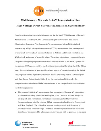
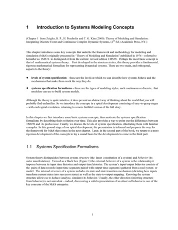
Modeling and Simulation of HVDC and HVAC Transmission Line(IJSRD/Vol. 3/Issue 05/2015/141)characteristics determines the mode of operation of eachconverter. In general, there are three modes of operation ofDC link. These three modes are defined as Constant Current Control (CCC) at rectifier(operating point A) and Constant Extinction Angleat inverter which is normal mode of operation. With slight dip in AC voltage, the operating mode(point C) changes as minimum α at rectifier andminimum γ at inverter. With lower AC voltage, mode of operation shifts as Constant Current Control (CCC) at inverter andminimum α at rectifier.Fig. 3 Converter Control CharacteristicsRectifier Inverter Mode of operationABHGMinimumBCGFConstant currentCDFEMinimumTable 4: ParameterThese modes of operation are used in the model areto be controlled for the stability of the system. The controlsystem modelling consists of α and γ angles measurementsat rectifier and inverter respectively. These values arecontinuously monitored for producing corresponding firingpulses to both inverter and rectifier.The control schemes used in this system are asfollows: Constant Extinction Angle (γ) controller DC current controller Voltage Dependent Current Order Limiter(VDCOL)6) Rectifier Control:The rectifier controller uses Constant Current Controller(CCC) scheme. The current is adjusted to constant bymodifying the α i.e., firing angle of the rectifier.The DC current equation of the rectifier is taken asFrom the above equation, it is observed that the DCcurrent can be maintained constant, only by changing thevoltage from the respective converter where the remainingparameters such as dc line resistance and rectifier andinverter resistances are constant. By considering theseparameters, rectifier controller is designed. The DC currentis passed through certain filters before comparing with thereference DC current. The error signal thus obtained passedthrough PI controller to obtain firing angle α value This αorder is passed through firing circuit to obtain theequidistant pulses for the valves. This rectifier model isshown in Fig.5.7) Inverter Control:Extinction Angle Control (EAC) or γ control and constantcurrent control is used on the inverter side. For this EAC,first the γ value is measured. The extinction angle control isof predictive type which uses the feedback for propercontrol. This uses AC voltage of inverter side and pulsesgiven to the inverter are taken as reference. The average andminimum γ angles thus obtained are used for γ control and αangle computation.The VDCOL is used for the γ control. With thereduced AC voltages, the DC voltage slightly dips, but thecurrent is intained constant. If there is sudden drop involtage then the DC current is also reduced such that theconverter control characteristics are altered. For this, themeasured DC current and DC voltage are passed throughcertain filters before they are applied to VDCOL. From thisthe limit for DC current reference is obtained. Similar tocurrent control in rectifier controller, the modelling ofcurrent control in inverter is done.The γ is measured through proper transducers andthe average value is used for the control. This γ control useserror signal of DC and mean γ value by restricting the firingangle order within the limits. The minimum angle of theangles are taken and passed through another PI controller forα order. These obtained angles are again compared and theminimum of the two is used for obtaining firing pulses. Thecomplete model of inverter controller is shown in Fig. 4.Fig. 4: Inverter controller modelFig. 5: Rectifier controller modelAll rights reserved by www.ijsrd.com609
Modeling and Simulation of HVDC and HVAC Transmission Line(IJSRD/Vol. 3/Issue 05/2015/141)IV. HVAC TRANSMISSION SYSTEMThe modern electrical power system is in the form of a largeinterconnected 3 phase HVAC network. The generatingstations, transmission and distribution systems areinterconnected to form a 3 phase HVAC system operatingsynchronously at the common single frequency of 50 hz.Generating stations, transmission lines and distributionsystems are the main components of an electric powersystem. Generating stations and distribution system areconnected through transmission lines. HVAC transmissionsystem is generally used to interconnect two synchronousAC systems. At generating station, generated at a voltage of11 to 25 kv which then is stepped up to the transmissionlevels in the range of 66 to 765 kv. As the transmissioncapability of a line is proportional to the square of itsvoltage. HVAC using power transformer to step up voltageand this high voltage AC transmit to give substation. Thissubstation stepdown the voltage with the help stepdowntransformer and supply to load. In transmission case, thetransmitted power is send through overhead line in anytransmission link configuration such as 3 phase transmissionline. In HVAC transmission line needs compensation ofreactive power. This is provided by svs, shunt reactors,shunt capacitors etc, installed in substations. Intermediatesubstations are necessary at interval of 250 km to 400 km.Power transfer ability of HVAC lines may be increased byusing series capacitors or adding a parallel line. The HVACtransmission line design is based on limits of corona, radiointerference, TV interference, electrical field at ground leveletc.The HVAC system schematic diagram modeled inthis paper is shown in fig.5A. The sending end side of the system consist ofAC supply network, transformer, circuit breaker etc. ACgenerator generate 13.8 kv which is then step up to 735 kvand transmitting power from a power plant consisting of six350 MVA generators to an equivalent system trough a 600km transmission line. The transmission line is split into two300 km lines connected between buses B1, B2, and B3shown in fig. 6.C. Circuit BreakerEach series compensation bank is protected by metal-oxidevaristors (MOV1 and MOV2).The two circuit breakers ofline 1 are shown as CB1 and CB2.The function of a circuitbreaker is to isolate the faulty part of the power system incase of abnormal conditions.Fig. 6: Schematic model of HVAC systemV. MODELING OF HVAC SYSTEMThe system used in this model is a Series-compensatedtransmission system of rating 753KV, 1500MW as shown inFig.7.MATLAB/SIMULIgNK software is used for themodelling of this model. It is one of the simulation tool usedfor the study, analysis and application development whichuses both functional commands and block sets for designing.SimPowerSystems is one its designing tool used formodelling and simulating electric power systems inSIMULINK environment. This tool has common blocks ofthe both electrical and electronic devices that are predesigned satisfying the related equations. Also this softwarehas the flexibility in modifying the block sets according tothe user.A. TransformerTransformer is another major component of a HVACtransmission system. It transfer power with very highefficiency from one level of voltage to another level. Inorder to supply power to transmission line transformerhaving delta (D1)star configuration are used. A Threephase transformer (two winding) block and a three phasetransformer (three windings) block are used to model thetwo transformers. Saturation is implemented on thetransformer connected at bus B2.B. Series Shunt CompensatorTo increase the transmission capacity, each line is seriescompensated by capacitors representing 40% of the linereactance. Both lines are also shunt compensated by a 330MVAR shunt reactance. The shunt and series compensationequipment is located at the B2 substation where 300 MVA735/230 KV transformers feed a 230 kv-250 MW load.Fig. 7: HVAC simulated modelThree phase source table VParametersValuesBase voltage735 KVBase MVA2100 MVANominal voltage13.8 KVBase power100 MWFrequency50 Hz 0.22/15Source Impedance 0.22All rights reserved by www.ijsrd.com610
Modeling and Simulation of HVDC and HVAC Transmission Line(IJSRD/Vol. 3/Issue 05/2015/141)Table 5: ParametersParametersWinding 1 Winding 2Power Rating 2100 MVA 2100 MVAVoltage Rating13.8 KV735 KVFrequency50 Hz50 HzConfigurationDeltaStarTable 6: Tansformer tableParametersValuesDistance300 KMFrequency50 HzResistance 0.0127 ohm/kmInductance0.933 mH/kmCapacitance12.74 nF/kmTable 7: AC Transmission lineVI. SIMULATION RESULTSMATLAB (Simulink) simulation software is used tosimulate both HVDC and HVAC transmission systems.From the comparision of the simulation output betterperformance and higher reliability is demonstrated forHVDC transmission system. Study the behaviour of asystemwithout building it. Results are accurate in general,compared to analytical model. Help to find un-expectedphenomenon, behaviour of the system. Easy to perform―what-if‖ analysis. In HVDC system, the system has beensimulated for a period of 1s and at a sampling rate of 5μs.From the obtained results, it can be observed that the firingangle and extinction angle of the inverter are improved byincluding transmission line. It can be observed that thetransmission systems are planned, designed and installed togive guaranteed performance low losses, high availability,specified control characteristics etc.transmission lines where the performance observed is better.The scope for further work is to find fault location intransmission, comparison of power losses in HVDC andHVAC transmission systems.REFERENCES[1] M.O.Faruque and Yuyan Zhang, ―Detailed modeling ofCIGRÉHVDCbenchmarksystemusingPSCAD/EMTDC and PSB/SIMULINK‖, IEEE Trans.Power Delivery, vol 21, no.1 Dec 2006[2] M.Szechtman, T.Wess and C.V.Thio, ―A benchmarkmodel for HVDC system studies,‖ Proc. Int.Conf.AC/DC Power Transmission, Sep 17 – 20, 1991,pp. 374-378.[3] K.R.Padiyar, ―HVDC power transmission systems,‖second edition, New age international publishers.[4] Bimbal Bose, ―Power electronics and motor drivesadvances and trends‖, ELSEVIER.[5] Daniel Wart, ―Power electronics,‖ Tata McGraw-Hilledition.[6] Fenyan Yang, Zheng Xu, ―An approach to select PIparameters of HVDC controllers,‖ Power Eng . Societygeneral meeting 2006.[7] S.RAO, ―EHV-AC, HVDC transmission & distributionengineering,‖third edition, Khanna publishers.[8] Converter System Nonlinear Modelling And ControlFor Transmission Applications—Part I: VSC SystemIEEE TRANSACTIONS ON POWER DELIVERY,VOL. 28, NO. 3, JULY 2013[9] PRABHA KUNDUR, ―Power System Stability andControl‖ Tata McGraw-HillVII. CONCLUSIONOne of the primary advantage of modling and simulation ofHVDC and HVAC transmission is that they are able toprovide users with practical feedback when designing realworld systems. This allows to determine the correctness andefficiency of a design before the system is actuallyconstructed. Another benefit of modelling and simulation ofHVDC and HVAC transmission sytems they permit systemto study a problem at several different levels of abstraction.With the help of modelling and simulation of HVDC andHVAC transmission systems we analysis overall system.The execution time in the simulation of the model for timeduration of 2s with a time step of 50μs is 26 which areobtained by cpu time command. For large and complexHVAC systems are usually describe by nonlinear modelsand thus are not tractable for analytical approaches except inspecial cases. Simulation is the only tool for predictingaccurately the system performance under various operatingconditions or when subjected to certain disturbances. Thismodeling and simulation of HVDC and HVAC transmissionline are used to compare power losses in HVDC and HVACtransmission line. Power loss is one of main factors thataffect project cost, so the transmission line models areimplemented to calculate the power loss. Parameters of themodel include impedance of transmission line, powerfrequency, transmission line voltage and amount of power tobe transmitted. This model can be applied for long distanceAll rights reserved by www.ijsrd.com611
the simulation software. Section IV of this paper gives a brief introduction about the HVAC system model. Section V gives description of how the HVAC system is modeled in the simulation software. Section VI shows the simulation results of the model and it is followed by conclusion. II. HVDC TRANSMISSION SYSTEM